Loading ...
Loading ...
Loading ...
SDS5000X Series Digital Oscilloscope User Manual
33 / 2 3 6 W W W. S I G L E N T. C O M
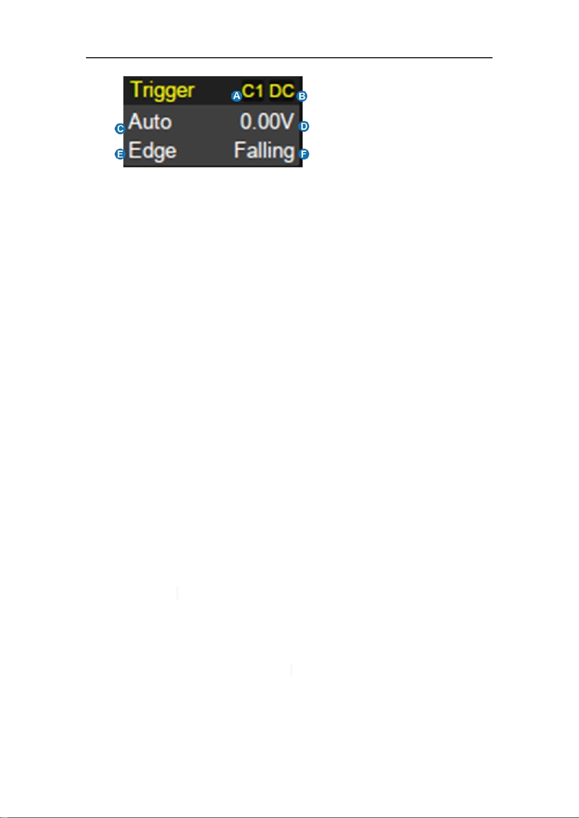
A. Trigger source
B. Trigger coupling
C. Trigger mode
D. Trigger level
E. Trigger type
F. Trigger slope
Trigger source
C1~C4: Analog channels
EXT: External trigger channel
EXT/5: 5x attenuation of external trigger channel
AC Line: AC mains supply
D0~D15: Digital channels
Trigger coupling: Coupling mode of the current trigger source. It is only valid
when the trigger source is C1~C4, EXT or EXT/5.
DC:All the signal’s frequency components are coupled to the trigger
circuit for high frequency bursts or where the use of AC coupling would
shift the effective trigger level.
AC:The signal is capacitively coupled. DC levels are rejected. See the
datasheet for details of the cut-off frequency.
HFR: Signals are DC coupled to the trigger circuit, and a low-pass filter
network attenuates high frequencies (used for triggering on low
frequencies). See the datasheet for details of the cut-off frequency.
LFR:The signal is coupled through a capacitive high-pass filter network,
DC is rejected and low frequencies are attenuated. For stable triggering
Loading ...
Loading ...
Loading ...