Loading ...
Loading ...
Loading ...
5. Adjustment is complete when both locking and
indexing functions are working properly. Replace
motor support cover.
ADJUSTING SWIVEL LOCK HANDLE
This handle provides a friction lock between the
upper face of the yoke and the bottom face of the
carriage. It should eliminate any play or rotation
between these two parts when locked. An adjustment
is required if the yoke can be easily rotated by hand
when handle is locked or yoke lock handle offers
minimal resistance when moving handle to the
locked position. To make this adjustment:
(NOTE: On electronic models the rip encoder must
be removed first with Phillips screwdriver.)
1. With a 1/2 wrench or socket remove six (6) 5/16-
18 hex head tapping screws and separate track
from arm as illustrated.
2. Slide yoke assembly from track. Keep carriage in
line with track until rip lock mechanism clears
end of track.
3. With a 15/16 wrench or socket tighten the 5/8-1 1
hex nut until maximum effort is required to place
yoke lock handle in the locked position.
4. Unlock yoke lock handle and swivel yoke to an
unindexed position. Return yoke to an indexed
position. If the yoke does not index securely the
adjustment is too tight. Loosen 5/8-11 hex nut
until swivel index pin seats properly.
5. Adjustment is complete when both locking and
indexing functions are working properly.
6. Slide carriage onto track starting with rip lock
mechanism. Keep carriage in line with track until
all of the bearings are on the track. Be careful not
to catch the wipers on the edge of the track.
7. Re-attach track to arm using six (6) 5/16-18 hex
head tapping screws.
(On electronic units the rip encoder must be re-
attached at this time.)
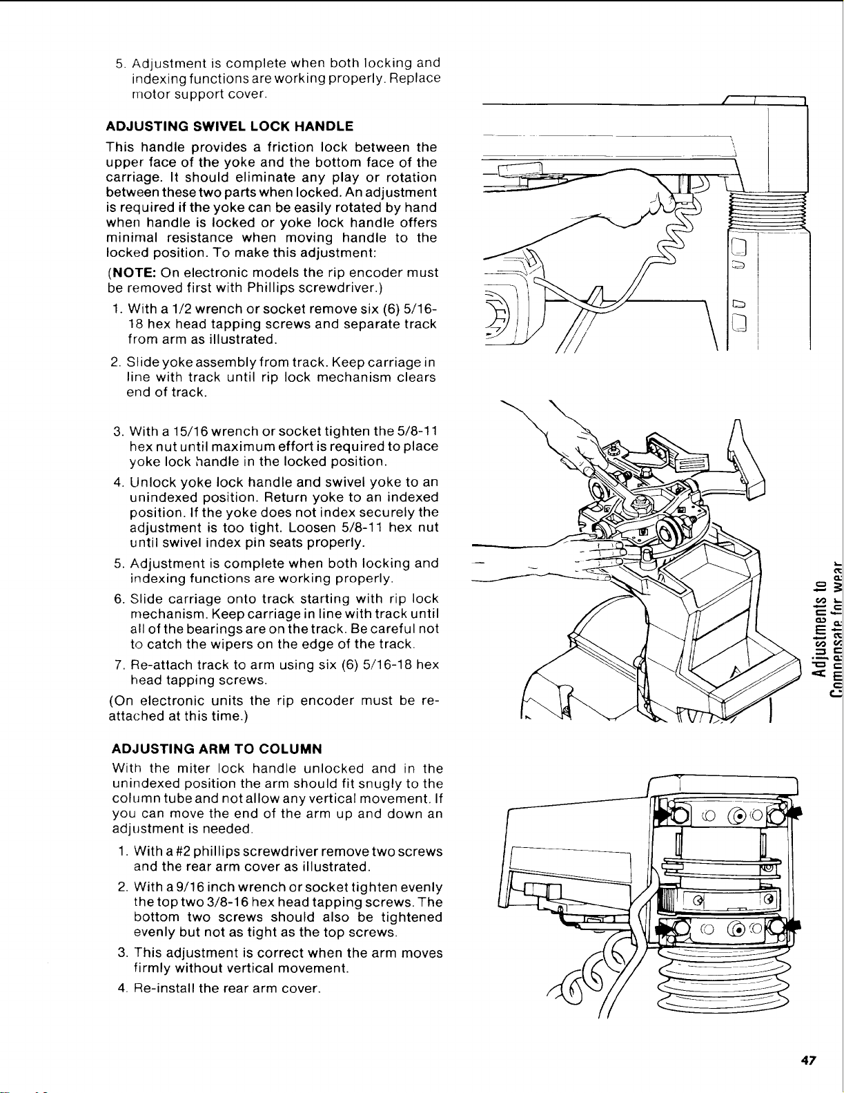
ADJUSTING ARM TO COLUMN
With the miter lock handle unlocked and in the
unindexed position the arm should fit snugly to the
column tube and not allow any vertical movement. If
you can move the end of the arm up and down an
adjustment is needed.
1. With a#2 phillips screwdriver remove two screws
and the rear arm cover as illustrated.
2. With a 9/16 inch wrench or socket tighten evenly
the top two 3/8-16 hex head tapping screws. The
bottom two screws should also be tightened
evenly but not as tight as the top screws.
3. This adjustment is correct when the arm moves
firmly without vertical movement.
4. Re-install the rear arm cover.
\
©
#,
6@ t_,
.=_._
47
Loading ...
Loading ...
Loading ...