Loading ...
Loading ...
Loading ...
ALIGNMENT PROCEDURE
IMPORTANT: In order to obtain maximum cutting
accuracy and safety, the following six steps must be
carefully followed. Become thoroughly familiar with
these steps so that you can always maintain your
saw in proper alignment. The accuracy of each
adjustment is always dependent upon the accuracy
of the preceeding adjustment.
Be sure to align the saw in the exact sequence
described to insure proper alignment and cutting
accuracy.
After following the 6 step assembly and alignment
procedure and the Basic Saw operation section refer
to Trouble Shooting section if any difficulty is
experienced when performing any sawing operation.
STEP ONE
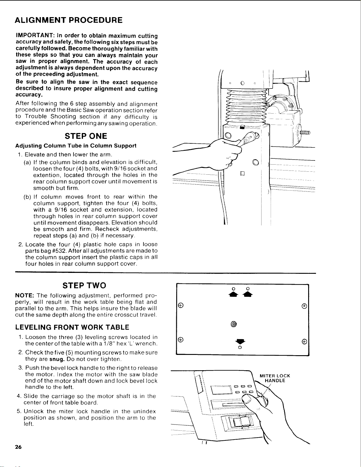
Adjusting Column Tube in Column Support
1. Elevate and then lower the arm.
(a) If the column binds and elevation is difficult,
loosen the four (4) bolts, with 9/16 socket and
extention, located through the holes in the
rear column support cover until movement is
smooth but firm.
(b) If column moves front to rear within the
column support, tighten the four (4) bolts,
with a 9/16 socket and extension, located
through holes in rear column support cover
until movement disappears. Elevation should
be smooth and firm. Recheck adjustments,
repeat steps (a) and (b) if necessary.
2. Locate the four (4) plastic hole caps in loose
parts bag #532. After all adjustments are made to
the column support insert the plastic caps in all
four holes in rear column support cover.
o O o _
/
STEP TWO
NOTE: The following adjustment, performed pro-
perly, will result in the work table being flat and
parallel to the arm. This helps insure the blade will
cut the same depth along the entire crosscut travel.
LEVELING FRONT WORK TABLE
1. Loosen the three (3) leveling screws located in
the center of the table with a 1/8" hex'L'wrench.
2. Check the five (5) mounting screws to make sure
they are snug. Do not over tighten.
3. Push the bevel lock handle to the right to release
the motor. Index the motor with the saw blade
end of the motor shaft down and lock bevel lock
handle to the left.
4. Slide the carriage so the motor shaft is in the
center of front table board.
5. Unlock the miter lock handle in the unindex
position as shown, and position the arm to the
left.
@
®
o o
-lb -Ib
@
MITER LOCK
HANDLE
®
®
/ I
26
Loading ...
Loading ...
Loading ...