Loading ...
Loading ...
Loading ...
Adjusting front table lock handles
WARNING: TO AVOID SUDDEN SLIPPAGE,
BREAKAGE, OR THROWING OF PARTS, FRONT
TABLE BOARD LOCK HANDLE MUST LOCK
TABLE BOARDS AND RIP FENCE SECURELY IN
PLACE.
1. To adjust the table board clamps check by
pulling up on rip fence. There should be enough
pressure to keep the rip fence from pulling up. To
adjust the pressure on the clamp:
a. Lift front table lock handles up to release
pressure on boards.
b. Loosen the two eccentric spacer clamps
located at the rear of the table top with a
7/16" wrench or socket.
c. Rotate the spacer toward the rear table board.
Tighten spacer with 7/16" wrench or socket.
Repeat procedure for clamp on other side.
d. Push down on front lock handles and recheck
pressure by pulling up on rip fence. If rip fence
is too loose, repeat adjustment.
/
STEP THREE
Squaring Crosscut Travel
NOTE: This adjustment helps ensure the blade
accurately travels square to the rip fence.
1. Index arm at 0° miter and lock.
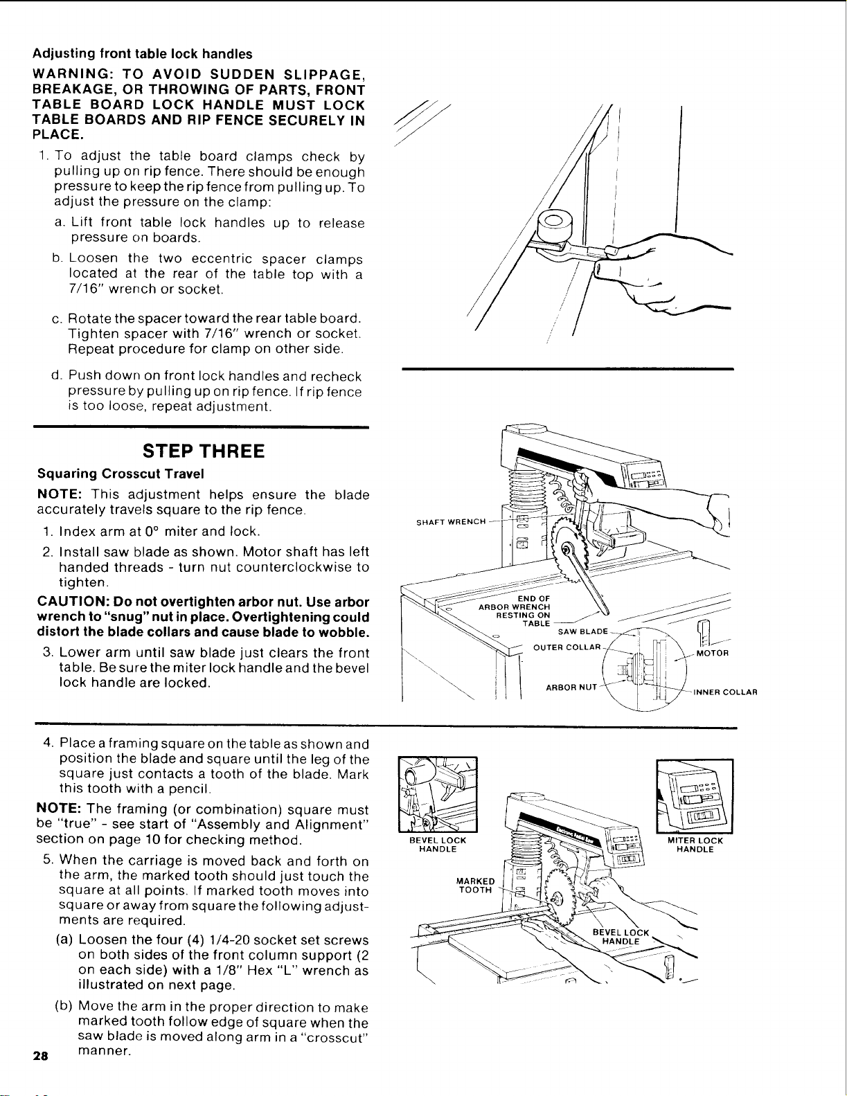
2. Install saw blade as shown. Motor shaft has left
handed threads - turn nut counterclockwise to
tighten.
CAUTION: Do not overtighten arbor nut. Use arbor
wrench to "snug" nut in place. Overtightening could
distort the blade collars and cause blade to wobble.
3. Lower arm until saw blade just clears the front
table. Be sure the miter lock handle and the bevel
lock handle are locked.
SHAFT
\
4. Placea framing square on the table as shown and
position the blade and square until the leg of the
square just contacts a tooth of the blade. Mark
this tooth with a pencil.
NOTE: The framing (or combination) square must
be "true" - see start of "Assembly and Alignment"
section on page 10 for checking method.
5. When the carriage is moved back and forth on
the arm, the marked tooth should just touch the
square at all points. If marked tooth moves into
square or away from square the following adjust-
ments are required.
(a) Loosen the four (4) 1/4-20 socket set screws
on both sides of the front column support (2
on each side) with a 1/8" Hex "L" wrench as
illustrated on next page.
28
(b) Move the arm in the proper direction to make
marked tooth follow edge of square when the
saw blade is moved along arm in a "crosscut"
manner.
BEVEL LOCK
HANDLE
MARKED
TOOTH
MITER LOCK
HANDLE
Loading ...
Loading ...
Loading ...