Loading ...
Loading ...
Loading ...
AUXILIARYFENCEFORMOLDING
To use the molding head with the arm in the 0 °
crosscut position an auxiliary fence must be used.
WARNING: IF THE AUXILIARY FENCE IS NOT
USED WHEN THE SAWARM ISIN THE0 ° CROSS-
CUT POSITION, THE MOLDING HEAD CANNOT
BE LOCATED BEHIND THE FENCE FOR SAFE
AND PROPER OPERATION.
Make the auxiliary fence from a piece of knot free
pine. Cut to the following dimensions.
--18-3/4" --1 _'_18"1/4" _i i
3/4"
Follow the instructions that are contained in an
Owner's Manual furnished with the molding head.
For use of the molding head or drum sander with saw
arbor vertical the rear table requires an opening
(next to rear face of fence) for arbor clearance. Cut
opening directly below arbor in vertical position.
Opening should be:
H F
When using the accessory shaft, the guard, saw
blade, dado, mold head or other cutting tool must be
removed from the saw arbor before using the acces-
sory shaft. Never operate the saw with cutting tools
(including sanding accessories, buffing wheels and
drill chuck) installed on both ends of the saw arbor.
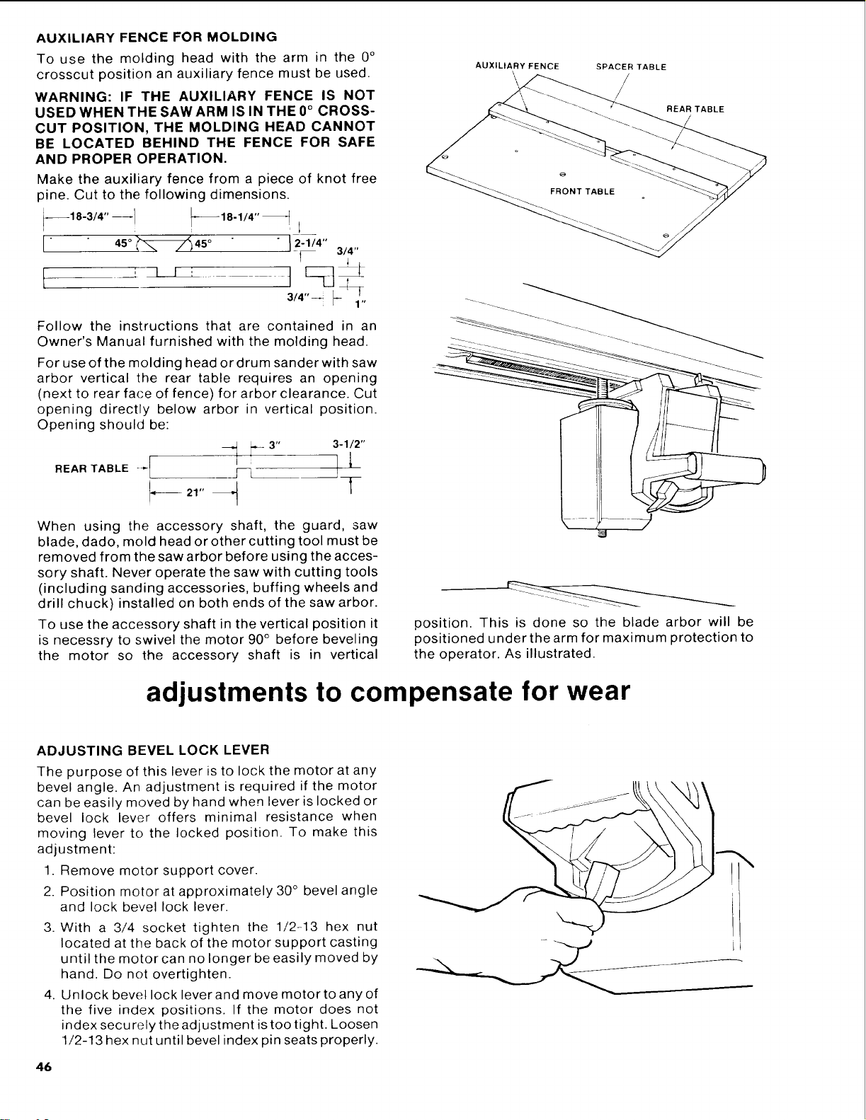
To use the accessory shaft in the vertical position it
is necessry to swivel the motor 90 ° before beveling
the motor so the accessory shaft is in vertical
AUXILIARY FENCE
SPACER TABLE
//
REAR TABLE
\ , i
position. This is done so the blade arbor will be
positioned under the arm for maximum protection to
the operator. As illustrated.
adjustments to compensate for wear
ADJUSTING BEVEL LOCK LEVER
The purpose of this lever is to lock the motor at any
bevel angle. An adjustment is required if the motor
can be easily moved by hand when lever is locked or
bevel lock lever offers minimal resistance when
moving lever to the locked position. To make this
adjustment:
1. Remove motor support cover.
2. Position motor at approximately 30 ° bevel angle
and lock bevel lock lever.
3. With a 3/4 socket tighten the 1/2-13 hex nut
located at the back of the motor support casting
untilthe motor can no longer be easily moved by
hand. Do not overtighten.
4. Unlock bevel lock leverand move motor to any of
the five index positions. If the motor does not
index secu rely the adjustment is too tight. Loosen
1/2-13 hex nut until bevel index pin seats properly.
46
Loading ...
Loading ...
Loading ...