Loading ...
Loading ...
Loading ...
d.
Loosen the miter angle encoder mounting
bracket by backing the mounting screws off
until the encoder will rotate slightly on the
column tube.
e. Rotate the encoder on the tube by tapping the
encoder lightly until the display reads "45.0".
Do not force or hit the encoder to make this
adjustment.
f. Re-tighten the encoder mounting screws and
re-check the encoder display using steps 1
through 6 above.
g. If the adjustment will not align the display
readings to the miter index positions, refer to
the trouble shooting guide in this manual.
h. When the encoder alignment has been com-
pleted, reinstall the arm rear cover to the arm.
Aligning the Bevel Angle Encoder
1. Turn the electronic display "On" by pressing
the _ key.
2. Press the [BEVEL
key.
3. Ensure that the motor is at the 0° bevel index
position (blade vertical) and that the bevel lock
handle is in the locked position.
4. Pressthe _iR_FSET!_key. Thedis-
play should be: .Ev .0
(Refer to the Trouble Shooting
section of the manual if the dis-
play is not as illustrated.)
5. Unlock the motor by pushing the bevel lock knob
to the far right. Rotate the motor to the 45 ° bevel
index position and lock. Display should now read
"45.0".
a. Unlock the motor and rotate the motor to the
90 ° bevel index position and lock. Display
should now read "90.00".
6. If the display does not read correctly, adjustment
of the bevel angle encoder is required. Follow the
procedure outlined to correct this alignment.
a. Set the motor to the 45 ° bevel index position.
Be sure that the bevel lock handle is in locked
position.
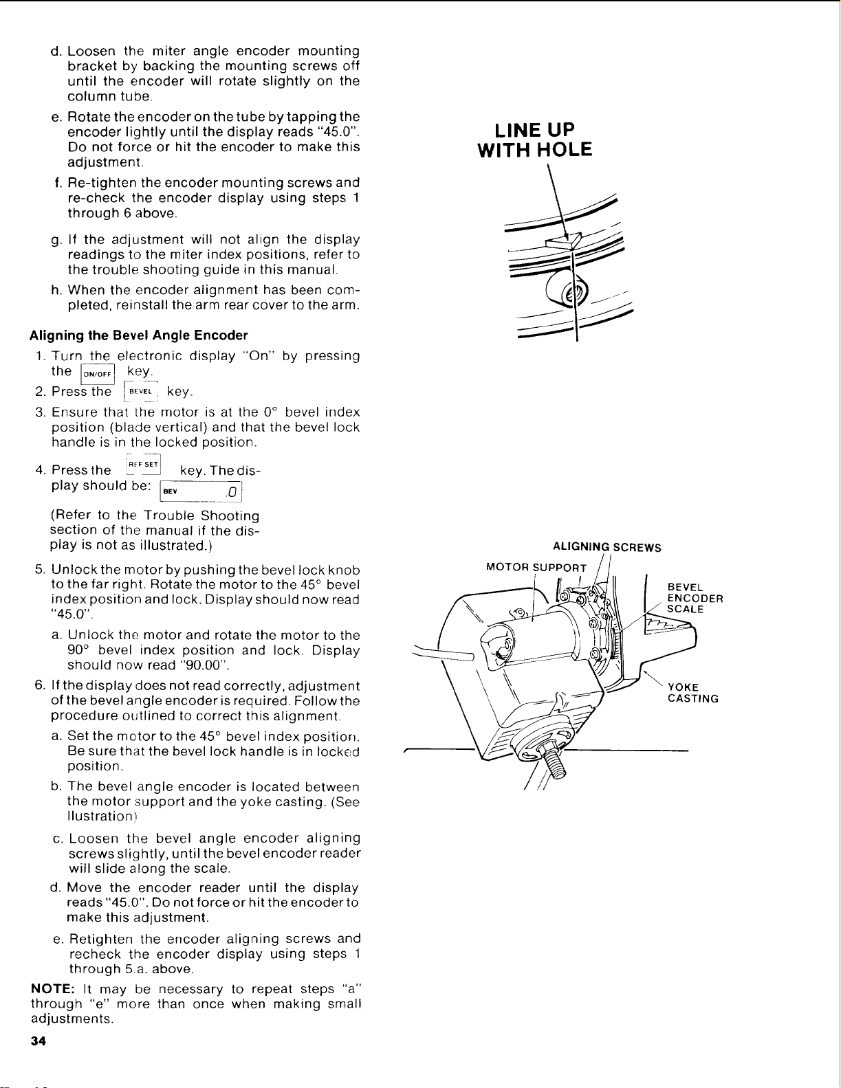
b. The bevel angle encoder is located between
the motor support and the yoke casting. (See
Ilustration)
c. Loosen the bevel angle encoder aligning
screws slightly, until the bevel encoder reader
will slide along the scale.
d. Move the encoder reader until the display
reads "45.0". Do not force or hit the encoder to
make this adjustment.
e. Retighten the encoder aligning screws and
recheck the encoder display using steps 1
through 5.a. above.
NOTE: It may be necessary to repeat steps "a"
through "e" more than once when making small
adjustments.
34
LINE UP
WITH HOLE
ALIGNING SCREWS
MOTOR SUPPORT
BEVEL
ENCODER
SCALE
YOKE
CASTING
Loading ...
Loading ...
Loading ...