Loading ...
Loading ...
Loading ...
(c) Carefully retighten uppertwo (2) 1/4-20 socket
set screws alternating from left side to right
side so as not to force arm out of adjustment.
(d) Recheck blade travel. Adjust arm position as
needed by readjusting upper screws only.
(e) Once arm position is good, tighten lower 1/4-
20 socket set screws. Do not overtighten.
Check elevating handwheel for ease of rota-
tion. If rotating handwheel is difficult, re-
adjust socket set screw tightness as needed.
NOTE: The life of your saw table will be lengthened
considerably if you will cover the front table with a
fitted piece of 1/4 inch plywood. This should be
tacked in place for easy replacement. Use of such a
cover will allow you to do all cutting into the cover,
rather than your table top. This will help prevent
dulling of the saw blade and striking table mounting
hardware. Place tacks out of the path of the saw
blade.
FOUR SOCKET
HEAD SCREWS
,=8:
STEP FOUR
Squaring Saw Blade to (Work) Table
NOTE: If alignment procedure step two was not
performed, this adjustment cannot be accomplished.
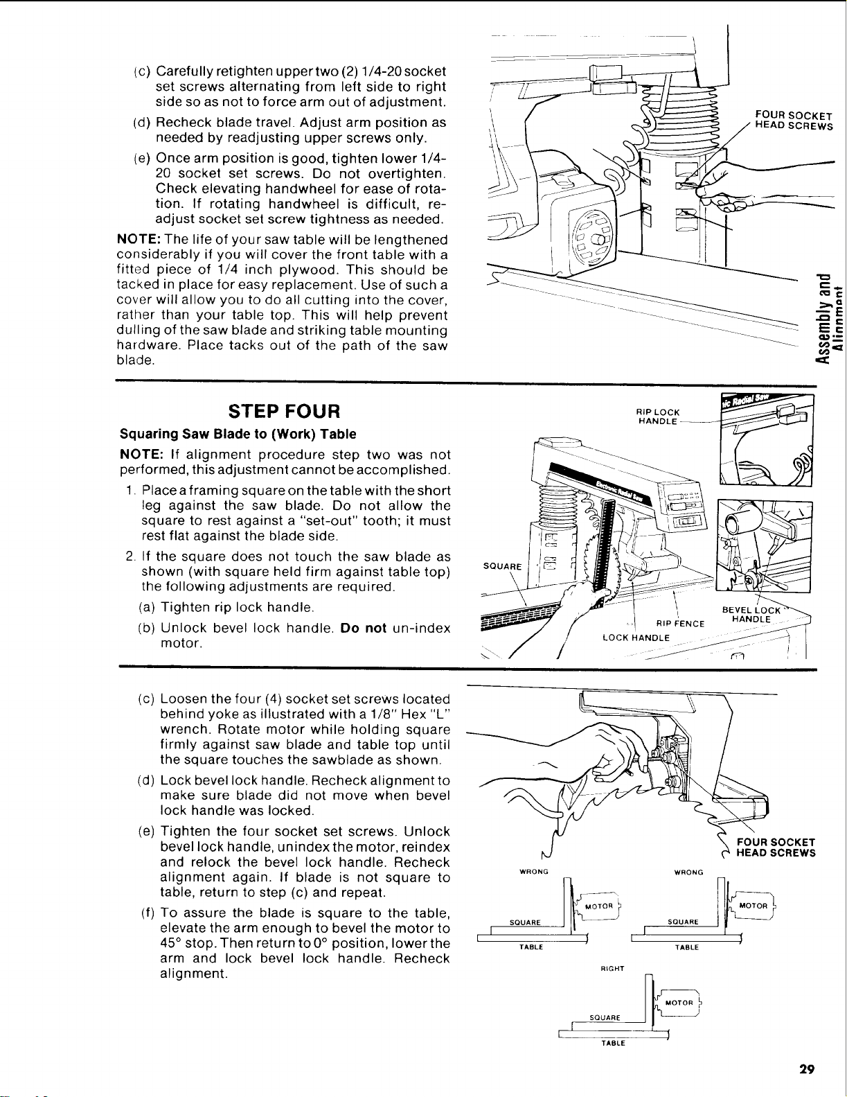
1. Place a framing square on the table with the short
leg against the saw blade. Do not allow the
square to rest against a "set-out" tooth; it must
rest flat against the blade side.
2. If the square does not touch the saw blade as
shown (with square held firm against table top)
the following adjustments are required.
(a) Tighten rip lock handle.
(b) Unlock bevel lock handle. Do not un-index
motor.
SQUARE
\
II1 BEVEL
RIP F:ENCE HAND_
(c)
(d)
Loosen the four (4) socket set screws located
behind yoke as illustrated with a 1/8" Hex "L"
wrench. Rotate motor while holding square
firmly against saw blade and table top until
the square touches the sawblade as shown.
Lock bevel lock handle. Recheck alignment to
make sure blade did not move when bevel
lock handle was locked.
(e) Tighten the four socket set screws. Unlock
bevel lock handle, unindex the motor, reindex
and relock the bevel lock handle. Recheck
alignment again. If blade is not square to
table, return to step (c) and repeat.
(f) To assure the blade is square to the table,
elevate the arm enough to bevel the motor to
45° stop. Then return to 0° position, lower the
arm and lock bevel lock handle. Recheck
alignment.
I _ FOUR SOCKET
t_J _ HEAD SCREWS
WRONG WRONG
SQUARE SQUARE
I
I
TABLE TABLE
RIGHT
MOTOR
SQUARE
TABLE
29
Loading ...
Loading ...
Loading ...