Loading ...
Loading ...
Loading ...
©
2019 DJI All Rights Reserved.
35
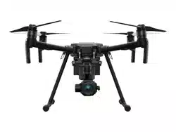
MATRICE 200
SERIES V2 User Manual
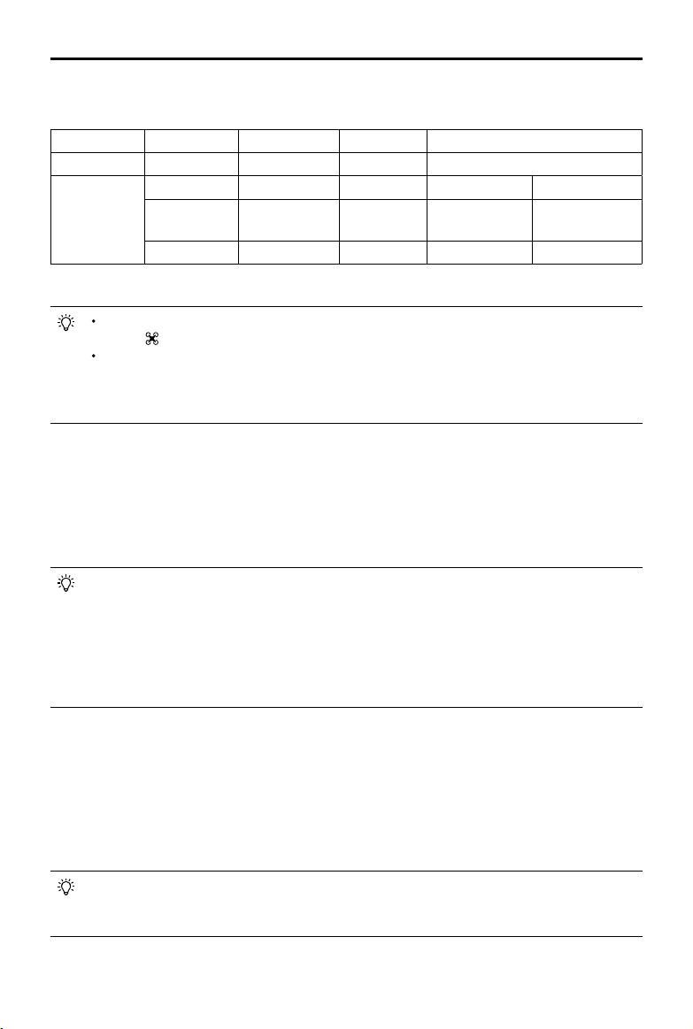
Pins Descriptions
PWM power level is 3.3V and all pins can be congured in DJI Pilot app.
Number 1 2 3 4
Name I/O port I/O port OSDK port Especially for an external GPS Kit*
Pins (from up
to down)
TIMESNYC GND GND / /
PWM3/GPIO3
PWM4/GPIO4/
HARDSYNC
SDK_RX / /
PWM1/GPIO1 PWM2/GPIO2 SDK_TX / /
* An external GPS Kit is required when a single upward gimbal or other payload is used on the M210 V2.
It is required to enable the expansion ports in the app before rst-time use. Go to Camera
View >
> Extended IO Conguration to set.
Make sure to install two batteries to the aircraft, power on the aircraft and wait for the
system to be ready when the power supply port is enabled in the app. Otherwise the
expansion ports cannot be used. When using in low-temperature environments, the
batteries must be preheated.
Usage of the TIMESYNC Pin
The TIMESYNC pin is for the TimeSync function. This function uses the PPS signal of the GPS
module or RTK module to synchronize the aircraft time to the UTC time, and provides the Onboard
SDK users with the precise UTC time of the rising edge of the TIMESYNC output pulse. Users
can apply this UTC timestamp to the data from their third-party payloads to achieve precise time
synchronization.
The TIME_SYNC pin provides output of the raw GPS and RTK data in GSA and RMC types
in the NMEA standard. For the M210 RTK V2 aircraft, if RTK is disabled, the output will be
the PPS signal of 5 Hz from the GPS module. If RTK is enabled, the output will be the PPS
signal of 5 Hz from the GPS module before the RTK module receives satellite data. Once
the RTK module receives satellite data, the output will always be the PPS signal of 1 Hz
from the RTK module. For the M210 V2 aircraft, the output will always be the PPS signal of 5
Hz from the GPS module.
Usage of the HARDSYNC Pin
The HARDSYNC pin is for the ight controller time synchronization function. This function uses the
synchronization hardware signal from the ight controller to synchronize the data from the aircraft’s
sensors (such as IMU, Vision System, camera) to the same clock source. It is an autonomous time
synchronization method that does not rely on external information so that it can achieve precise
ight controller time synchronization even in environment without satellite signals such as indoors or
area with building obstruction.
The HARDSYNC pin provides output of the data such as IMU data, images from the Vision
System, and camera data from the aircraft’s sensors. The output will start with a pulse
frequency of 20 Hz once the aircraft is powered on.
Loading ...
Loading ...
Loading ...