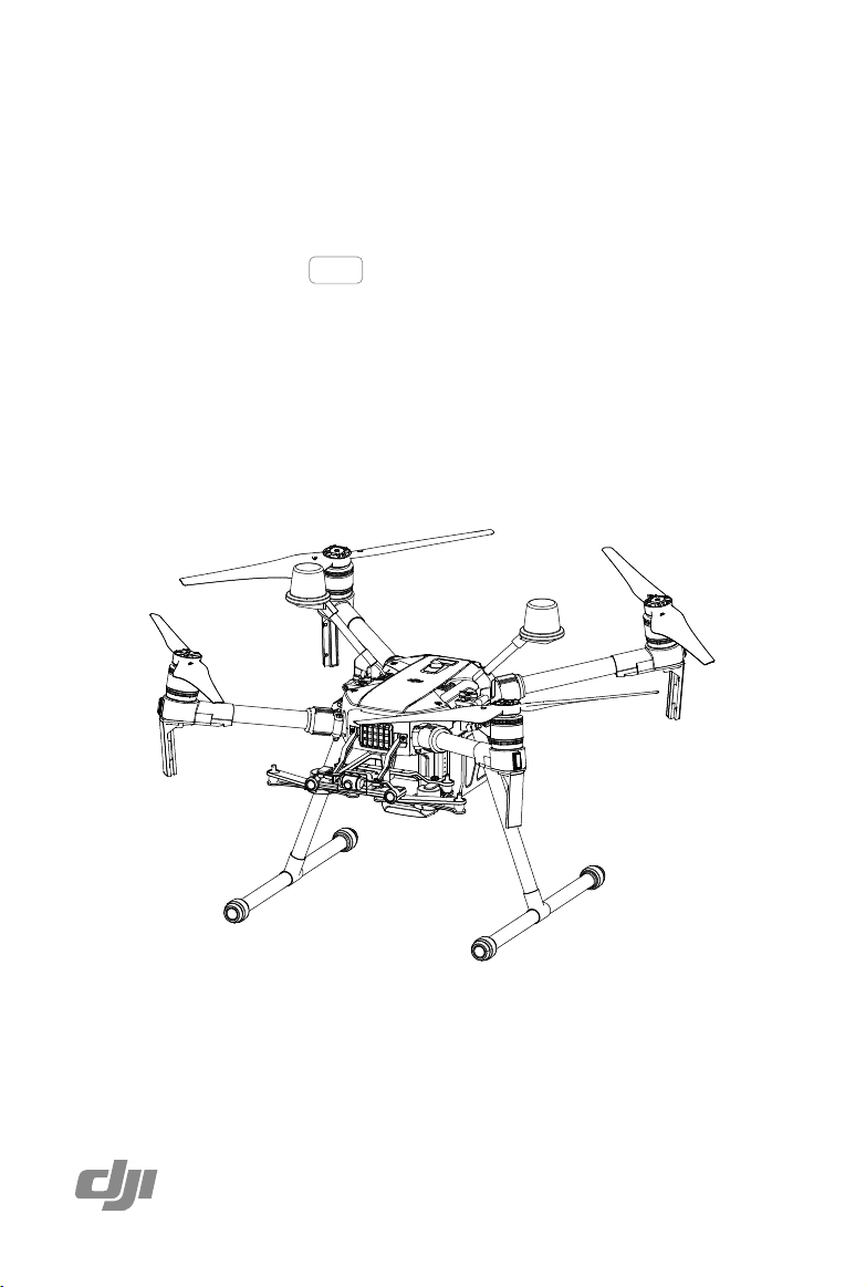
MATRICE 200 SERIES V2
M200 V2 / M210 V2 / M210 RTK V2
2020.07
v2.0
User Manual
2
©
2019 DJI All Rights Reserved.
Using This Manual
Legends
Warning Important Hints and Tips Reference
Before Flight
The following materials have been produced to help users make full use of the MATRICE
TM
210 V2 /
Matrice 210 RTK V2.
1. In the Box
2. Disclaimer and Safety Guidelines
3. Quick Start Guide
4. Intelligent Flight Battery Safety Guidelines
5. User Manual
Watching all the tutorial videos and reading the Disclaimer and Safety Guidelines before ight is
recommended. Afterwards, prepare for your rst ight by using the Quick Start Guide. Refer to this
manual for more comprehensive information.
Download the DJI Pilot app
The DJI Pilot app is required if using a mobile device connected to the remote
controller. Search for Scan the QR code or visit https://m.dji.net/djipilot_enterprise to
download the app. DJI Pilot supports Android 5.0 or later.
* For increased safety, the ight is restricted to a height of 30 m and distance of 50 m when not connected or logged into
the app during ight, including DJI Pilot and all apps compatible with DJI aircraft.
Download the DJI Assistant 2 for Matrice
Download and install the ASSISTANT
TM
2 for Matrice before use.
http://www.dji.com/matrice-200-series-v2/info#downloads
Searching for Keywords
Search for keywords such as “battery” and “install” to find a topic. If you are using Adobe
Acrobat Reader to read this document, press Ctrl+F on Windows or Command+F on Mac to
begin a search.
Navigating to a Topic
View a complete list of topics in the table of contents. Click on a topic to navigate to that section.
Printing this Document
This document supports high resolution printing.
The operating temperature of this product is -20° to 50° C. It does not meet the standard
operating temperature for military grade application (-55° to 125° C), which is required to
endure greater environmental variability. Operate the product appropriately and only for
applications that it meets the operating temperature range requirements of that grade.

©
2019 DJI All Rights Reserved.
3
Contents
Using This Manual
2
Legends 2
Before Flight 2
Download the DJI Pilot app 2
Download the DJI Assistant 2 for Matrice 2
Product Prole
5
Introduction 6
Feature Highlights 6
Assemble the Aircraft 7
Preparing the Remote Controller 9
Aircraft Diagram 11
Remote Controller Diagram 12
Aircraft
14
Prole 15
Flight Mode 15
Flight Status Indicator 16
Vision System and Infrared Sensing System 17
Return-to-Home (RTH) 21
Flight Recorder 26
Attaching and Detaching the Propellers 26
Center of Gravity Calibration 26
Spotlight Pro 26
DJI Intelligent Flight Battery 27
D-RTK (for M210 RTK V2) 32
DJI AirSense 33
Components at the Rear of the Aircraft 34
Remote Controller
37
Remote Controller Prole 38
Preparing the Remote Controller 38
Mounting the Monitor to the Remote Controller 40
Remote Controller Operations 41
Dual Remote Controller Mode 45
Remote Controller Screen Descriptions 47
Linking the Remote Controller 48
Mounting the Control Stick Covers 49

4
©
2019 DJI All Rights Reserved.
Gimbal and Camera
50
Camera 51
Gimbal 52
DJI Pilot App
54
Manual Flight 55
Mission Flight 59
Album 61
DJI FlightHub 61
Menu 61
Flight
62
Flight Environment Requirements 63
GEO (Geospatial Environment Online) System 63
Flight Restrictions 64
GEO Unlocking 67
Preight Checklist 67
Calibrating the Compass 67
Starting/Stopping the Motors 69
Stop the Motor Mid-ight 69
Flight Test 70
Appendix
72
Specications 73
Firmware Update 75
Using the Zenmuse XT Gimbal and Camera 76
Dual Downward Gimbals 77
Using the Upward Gimbal and GPS Kit 77
Carrying Box Descriptions 78

©
2019 DJI All Rights Reserved.
5
Product Prole
This chapter describes the features of
the Matrice 200 series V2, shows how
to assemble the aircraft, and contains
diagrams of the aircraft and remote
controller with component explanations.

6
©
2019 DJI All Rights Reserved.
Product Prole
Introduction
Matrice 200 V2 / Matrice 210 V2 / Matrice 210 RTK V2
(
M200 V2 / M210 V2 / M210 RTK V2) is a
powerful aerial imaging system with class-leading agility and speed, redundant components for
maximum reliability, and smart features that make performing complex tasks easy. The aircraft’s
visual sensors* enable enhanced hovering precision even when ying indoors or in environments
where GNSS is unavailable. Gimbal cameras can be easily exchanged to suit your application's
needs. Dual frequency transmission system makes HD video downlink more stable and efcient.
* The Vision and Infrared Sensing Systems are affected by surrounding conditions. Read the related section to
learn more.
Feature Highlights
The ight controller provides a safe and reliable ight experience. A ight recorder stores critical
data from each ight. Dual IMUs and barometers design provides redundancy. The aircraft can
hover and y in extremely low altitude and indoor environments, and provides multi-directional
obstacle sensing and vision positioning functions.
The built-in AirSense makes you aware of nearby aircraft in the surrounding airspace to ensure
safety. The safety beacons on both the top and the bottom of the aircraft allow the aircraft to be
identied at night or in low light conditions. The airframe design gives the aircraft an IP43 Ingress
Protection, in accordance with the global IEC 60529 standard.
The low-latency long range (up to 5 mi (8 km), FCC) HD downlink is powered by DJI OCUSYNC
TM
2.0. Support of 2.4 GHz and 5.8 GHz ensures a more reliable connection in environments with
more interference. The AES-256 encryption keeps your data transmission secure so you can be
sure that your critical information stays safe.
An advanced power management system along with dual batteries ensures power supply and
enhances ight safety. Without a payload, the M210 RTK V2 has a ight time of up to 33 minutes
with standard batteries (TB55), the M210 V2 has a ight time of up to 34 minutes, while the M200
V2 has up to 38 minutes of ight time.
The camera unit is now independent from image processor so that you have the flexibility to
choose the perfect gimbal and camera system (including ZENMUSETM X7/X5S/X4S/XT*/XT2/
XT S*, and Z30) for each of your application. This means that regardless of which camera you
choose, you have the same powerful processing backing it. M200 V2 series can support a single
downward gimbal.
M210 V2 and M210 RTK V2 have below features:
The M210 V2/M210 RTK V2 can support an upward gimbal**, a single downward gimbal
(connected to Gimbal Connector I) or dual downward gimbals. It is equipped with many
expansion ports to broaden its applications. The M210 RTK V2 has a built-in DJI D-RTKTM 2 air
system, which provides more accurate heading data for positioning.***
The TimeSync system continuously aligns the ight controller, camera, GPS module, RTK module
for the M210 RTK V2, DJI payloads such as X4S, X5S or X7, as well as onboard accessories
via the Payload SDK or Onboard SDK at the microsecond level. It meets SDK developers’
requirements on time precision.
* The Zenmuse XT Gimbal Adapter is required when mounting the Zenmuse XT gimbal to the aircraft. The
©
2019 DJI All Rights Reserved.
7
MATRICE 200
SERIES V2 User Manual
Zenmuse XT S is only available in select countries and regions.
** When using an upward gimbal with the M210 V2, an external GPS Kit connected through the expansion port
is required.
*** When using the M210 RTK V2, more accurate positioning data can be achieved when using a DJI D-RTK 2
High Precision GNSS Mobile Station for Matrice Series. If the data transmission signal between the aircraft
and the mobile station is weak, it is recommended to use post-processed kinematic (PPK) technology.
Assemble the Aircraft
This manual uses the M210 RTK V2 and Zenmuse Z30 as an example to demonstrate setup and
usage.
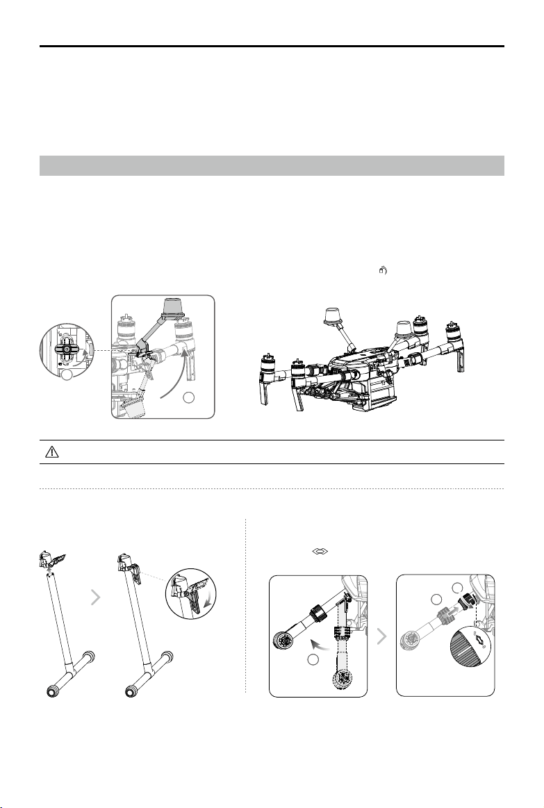
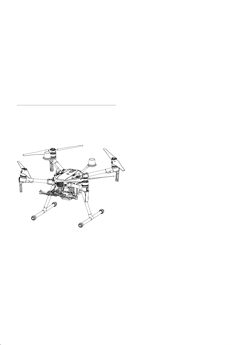
Installing the Landing Gears Unfolding the Aircraft
Unfold the frame arm, slide the arm lock to the end of the frame
arm, then rotate it about 90° until the silver line lies within the
range of the
icon.
1
2
3
Unfold the D-RTK antennas and then turn the knob tightly in the direction indicated by the lock icon .
Unfolding the D-RTK Antennas (for M210 RTK V2 only)
For the aircraft to take off, the D-RTK antennas must be fully unfolded and securely locked.
1
2
8
©
2019 DJI All Rights Reserved.
MATRICE 200
SERIES V2 User Manual
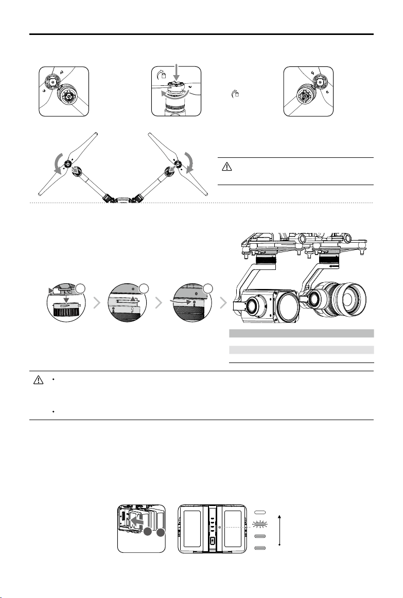
Make sure to press down the gimbal detachment button when rotating the gimbal lock to
remove the gimbal and camera. The gimbal lock should be fully rotated when removing
the gimbal for the next installation.
M200 V2 comes with a single downward gimbal.
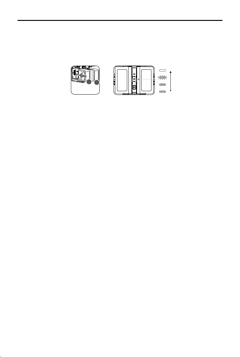
Mounting the Intelligent Flight Batteries
Insert a pair of batteries.
Press once to check the battery level.
Press again and hold until the batteries turn on or off.
Mounting the Gimbal and Camera
Press the Gimbal
Detachment button
to remove the cover.
Align the white
and red dots and
insert the gimbal.
Rotate the gimbal
lock to the locked
position.
Gimbal Connector II
Gimbal Connector I
Zenmuse XT Zenmuse X4S/X5S/X7/XT2/Z30
Zenmuse Z30 Zenmuse X4S/X5S/X7/XT/XT2/XT S
Zenmuse XT S Zenmuse X4S/X5S/X7/Z30
11
2 3
Low
High
A
B
Mounting the Propellers
Propellers
without silver
rings go on
motors without
any marks.
Press the propeller down
onto the mounting plate
and rotate in the lock
direction
until secure.
Propellers
with silver
rings go on
motors with
the same
color marks.
Check that the propellers are secure
before each ight.
©
2019 DJI All Rights Reserved.
9
MATRICE 200
SERIES V2 User Manual
Only use battery slot B when using one battery to supply power. In this case, the aircraft
can only be powered on, but cannot take off.
If for any reason only one battery is available during ight, land the aircraft immediately
and replace the batteries as soon as possible. In this case, the gimbal connectors and
the ports at rear of the aircraft cannot supply power to their connected devices.
Make sure to use the included TB55 batteries. DO NOT use any other type of batteries.
Removing the Intelligent Flight Battery
Make sure to press the battery removal button when removing the battery.
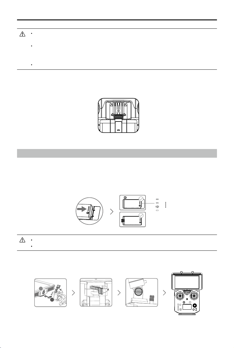
Preparing the Remote Controller
For M210 V2 / M210 RTK V2
Mounting Monitor and Remote Controller Batteries
CRYSTALSKY
TM
monitors and the remote controller use the same batteries.
Put the battery into the Battery Slot, then slide it to the end until you hear a click.
Press the Battery Release Button before removing the battery.
Press the Battery Level Button once to check the battery level.
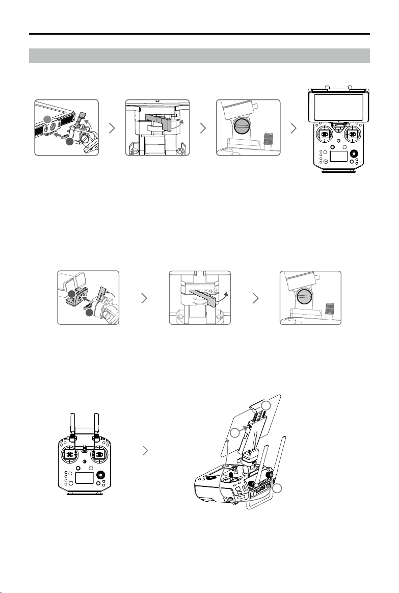
Mounting the Monitor to the Remote Controller
Low
High
Lock the Mounting
Bracket.
Use a coin or the
screwdriver included to
adjust the tightness of
the tilt axis.
Ensure that Part B is
unlocked. Connect
Part B to Part A.
A
B
10
©
2019 DJI All Rights Reserved.
MATRICE 200
SERIES V2 User Manual
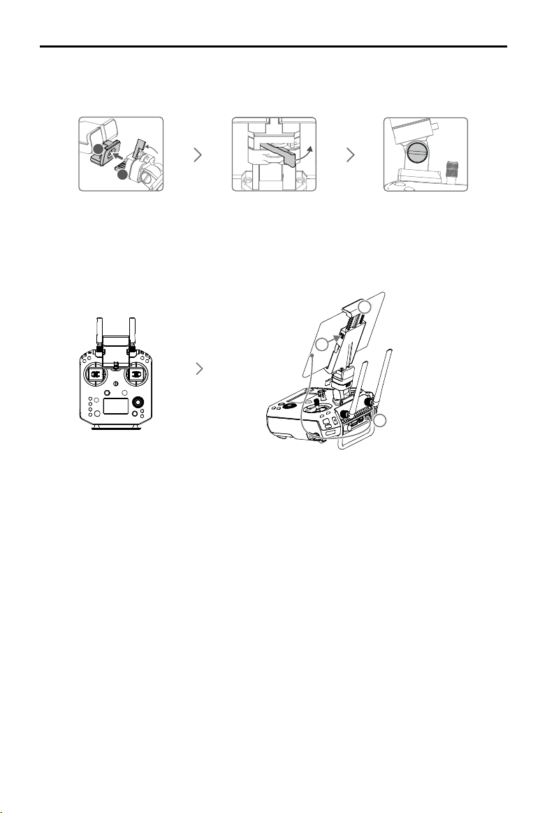
For M200 V2
Lock the Mounting
Bracket.
Use a coin or the
screwdriver included
to adjust the tightness
of the tilt axis.
Ensure that Part B is
unlocked. Connect
Part B to Part A.
Connecting the Mobile Device
Press the button to
release the clamp.
Place your mobile
device and adjust
the clamp to secure.
Connect your mobile
device with a USB cable.
A
B
2
3
1
Mounting the Monitor to the Remote Controller
©
2019 DJI All Rights Reserved.
11
MATRICE 200
SERIES V2 User Manual
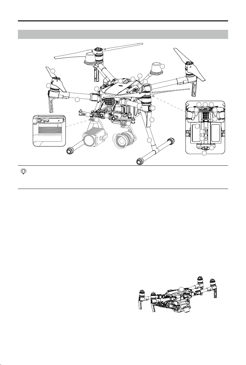
Aircraft Diagram
Folded
1. FPV Camera
2. Forward Vision System
3. DJI Gimbal Connector v2.0 (DGC2.0) I
4. DJI Gimbal Connector v2.0 (DGC2.0) II*
5. Gimbal Detachment Button
6. Frame Arms
7. Motors
8. Propellers
9. ESC LEDs
10. Transmission Antennas
11. Landing Gears
12. Upward Gimbal Mounting Position*
13. Beacons**
14. Upward Infrared Sensor
15. Aircraft Status Indicators
16. D-RTK Mounting Bracket***
17. D-RTK Antennas***
5
6
7
8
2
4
1
3
11
10
9
17
15
14
13
12
16
18
19 20 21
22
23
24
25
26
27
13
28
18. Extended Power Port (XT30)*
19. USB Mode Switch
20. USB Port
21. Linking Button and Indicator
22. Expansion Ports*
23. Battery Removal Button
24. Intelligent Flight Batteries
25. Battery Level Indicators
26. Power Button
27. Downward Vision System
28. microSD Card Slot
* Not come with the M200 V2.
** DO NOT look directly at the beacons when they are in use to avoid damage to your eyes.
*** Included in the M210 RTK V2 aircraft only.
The M200 V2 comes with a single downward gimbal connector. The M210 V2 and M210
RTK V2 each comes with a dual downward gimbal connector. The illustrations in this
manual may vary from the actual product.
12
©
2019 DJI All Rights Reserved.
MATRICE 200
SERIES V2 User Manual
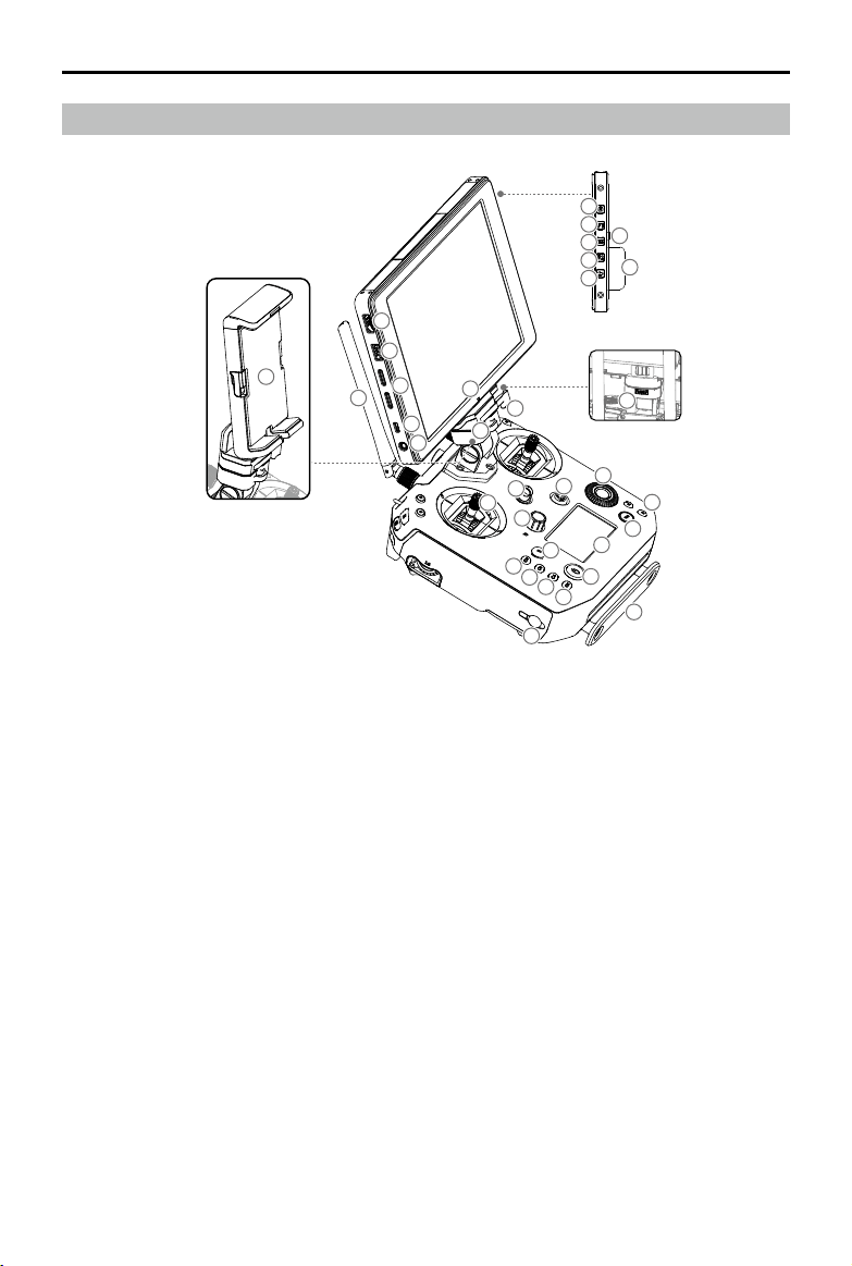
Remote Controller Diagram
1. HDMI Port
Output HDMI video signal.
2. USB Port
Supported extended device, e.g. U disk.
3. microSD Card Slot
Provides extra storage space for the display
device, maximum card size is 128 GB.
4. Micro USB Port
Use a Micro USB cable to connect to the
remote controller when in use, or to the PC to
congure parameters via DJI Assistant 2.
5. Headphone Jack
6. Light-Sensitive Port
Built-in light-sensitive sensor.
7. Power Button
8. Custom Button (F1)
9. Setting Button
10. Custom Button (F2)
11. Back Button
12. Battery Release Button
13. WB37 Intelligent Battery
14. Antennas
Relay aircraft control and video signal.
15. Monitor Mounting Bracket
Used to mount the DJI CrystalSky monitor* , or
mobile device with a holder.
16. USB Port (Reserved Port)
17. Control Sticks
Control the orientation and movement of the
aircraft.
18. Strap Hook
19. Focus Adjustment Knob
Rotate to set the focal length.
20. Return-to-Home (RTH) Button
Press and hold to initiate RTH.
21. Power Port
Connect to the Charger to charge the battery
of the remote controller.
22. Reserved Buttons
23. Shutter Setting Button
When using a Zenmuse X4S, X5S or X7, press
and rotate the Camera Setting Dial to set the
shutter speed.
15
7
8
10
9
11
13
12
16
2
5
4
1
3
14
6
17
18
18
19
48
20
21
22
23
24
25
26
27
28
29
30
31
32
M200 V2
M210 V2 / M210 RTK V2
©
2019 DJI All Rights Reserved.
13
MATRICE 200
SERIES V2 User Manual
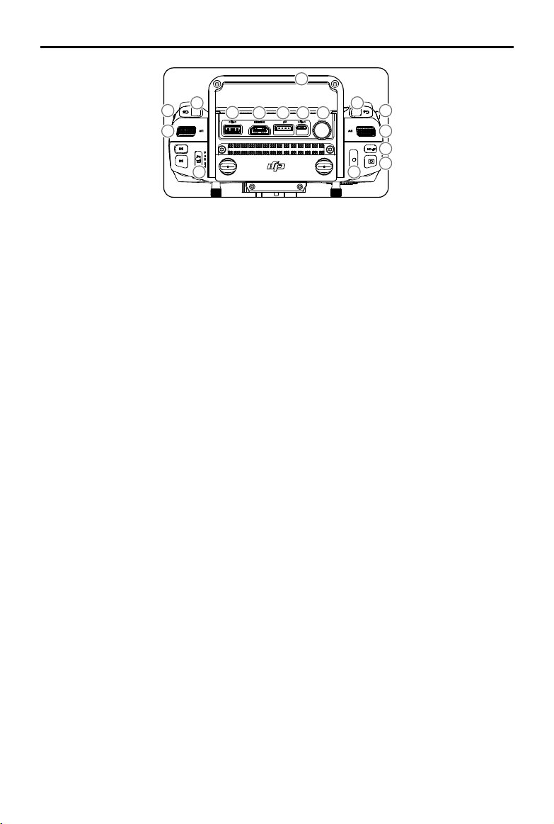
33
34
35
36
37
38 39 40 41
42
43
44
45
46
4747
24. Aperture Setting Button
When using a Zenmuse X4S, X5S or X7, press
and rotate the Camera Setting Dial to set the
aperture.
25. ISO Setting Button
When using a Zenmuse X4S, X5S or X7,
press and rotate the Camera Setting Dial to
set the ISO.
26. Pause Button
Press once and the aircraft will brake and hover.
27. Power Button
Used to turn the remote controller on and off.
28. Remote Controller Display
Shows information about the aircraft and
camera.
29. Camera Setting Dial
When using an X4S, X5S, X7 or Z30, turn the
dial to adjust the EV. When using an XT2 or XT,
turn the dial to select palette.
When using a Zenmuse X4S, X5S or X7,
press the Shutter Setting Button /Aperture
Setting Button / ISO Setting Button and rotate
the Camera Setting Dial to adjust the Shutter
/ Aperture / ISO.
30. Customizable Button Settings Menu
Press to set Customizable Button functions in
the DJI Pilot app.
31. Customizable Buttons (BA-BH)
Customizable through the DJI Pilot app.
32. Support Rig
33. Left Lever
Reserved.
34. Left Dial (Gimbal Pitch)
Controls gimbal pitch.
35. Flight Mode Switch
Switch between P-mode, S-mode, and
A-mode.
36. Handle Bar
37. USB Port (for Mobile Device Connection)
Connection to mobile device for DJI Pilot app
if used a third party mobile device.
38. HDMI A Port (for Video Output)
Output HDMI signal to an HDMI monitor.
39. CAN Bus Port (Extension Port)
Reserved port used to connect external
devices.
40. Micro USB Port
Connect to the DJI Assistant 2 for Matrice to
update rmware.
41. SDI Port (for Video Output)**
Output SDI video signal.
42. Right Lever
Reserved.
43. Right Dial
Used to control gimbal pan.
44. Auto Focus Button
Press to focus automatically.
45. Record Button
Press to start recording video. Press again to
stop recording.
46. Shutter Button
Press to take a photo. Photos can also be
captured during video recording.
47. Customizable Buttons (C1-C4)
Customizable through the DJI Pilot app.
48. Mobile Device Holder
* Note that CrystalSky does not come with the M200 V2.
** For better image transmission, a 75Ω coaxial cable is
required for SDI video signal output. Make sure to use
a coaxial cable with good electromagnetic shielding
performance to avoid signal interference which will
degrade the flight distance. Additionally, disable the
video output in the Image Transmission Settings in the
app when the display device is disconnected.
Aircraft
This section describes the features of
the Flight Controller, Vision System, and
the Intelligent Flight Battery.
©
2019 DJI All Rights Reserved.
15
Aircraft
Prole
The aircraft includes a flight controller, a communication system, vision systems, a propulsion
system and an Intelligent Flight Battery. This section describes the functions of these components.
Flight Mode
The following ight modes are available for the aircraft:
P-mode (Positioning) :
P-mode works best when the GPS signal is strong. The aircraft utilizes the GPS / RTK module
(for the M210 RTK V2 only) and Forward and Downward Vision Systems to locate itself,
automatically stabilize, and navigate between obstacles.
When the Forward Vision System is enabled and lighting conditions are sufcient, the maximum
flight attitude angle is 25°. When forward obstacle sensing is disabled, the maximum flight
attitude angle is 30°.
When the GPS signal is weak and lighting conditions are too dark for the Forward and
Downward Vision Systems, the aircraft will only use its barometer for positioning to control
altitude.
Note: P-mode requires larger stick movements to achieve higher speeds.
S-mode (Sport):
The aircraft uses GPS for positioning. As Forward and Downward Vision Systems are disabled,
the aircraft will not be able to sense and avoid obstacles when in Sport Mode.
Note: Aircraft responses are optimized for agility and speed making it more responsive to stick
movements.
A-mode (Attitude):
When neither the GPS nor the Vision Systems are available, the aircraft will only use its barometer
for positioning to control the altitude.
The Forward Vision System is disabled in S-mode (Sport), which means the aircraft will
not be able to automatically avoid obstacles in its ight path. Be vigilant and stay clear
of nearby obstacles.
The aircraft’s maximum speed and braking distance are signicantly increased in S-mode
(Sport). A minimum braking distance of 164 feet (50 meters) is required in windless
conditions.
The aircraft’s responsiveness is signicantly increased in S-mode (Sport), which means a small
stick movement on the remote controller will translate into a large travel distance of the aircraft.
Be vigilant and maintain adequate maneuvering space during ight.
Use the Flight Mode switch on the remote controller to select aircraft ight modes.
Atti Mode Warning
The aircraft will enter A-mode in the following two instances:
Passive: When there is weak GPS signal or when the compass experiences interference where the
Vision System is unavailable.
Active: Users toggle the ight mode switch to A-mode.
In A-mode, the Vision System and some advanced features are disabled. Therefore, the aircraft
16
©
2019 DJI All Rights Reserved.
MATRICE 200
SERIES V2 User Manual
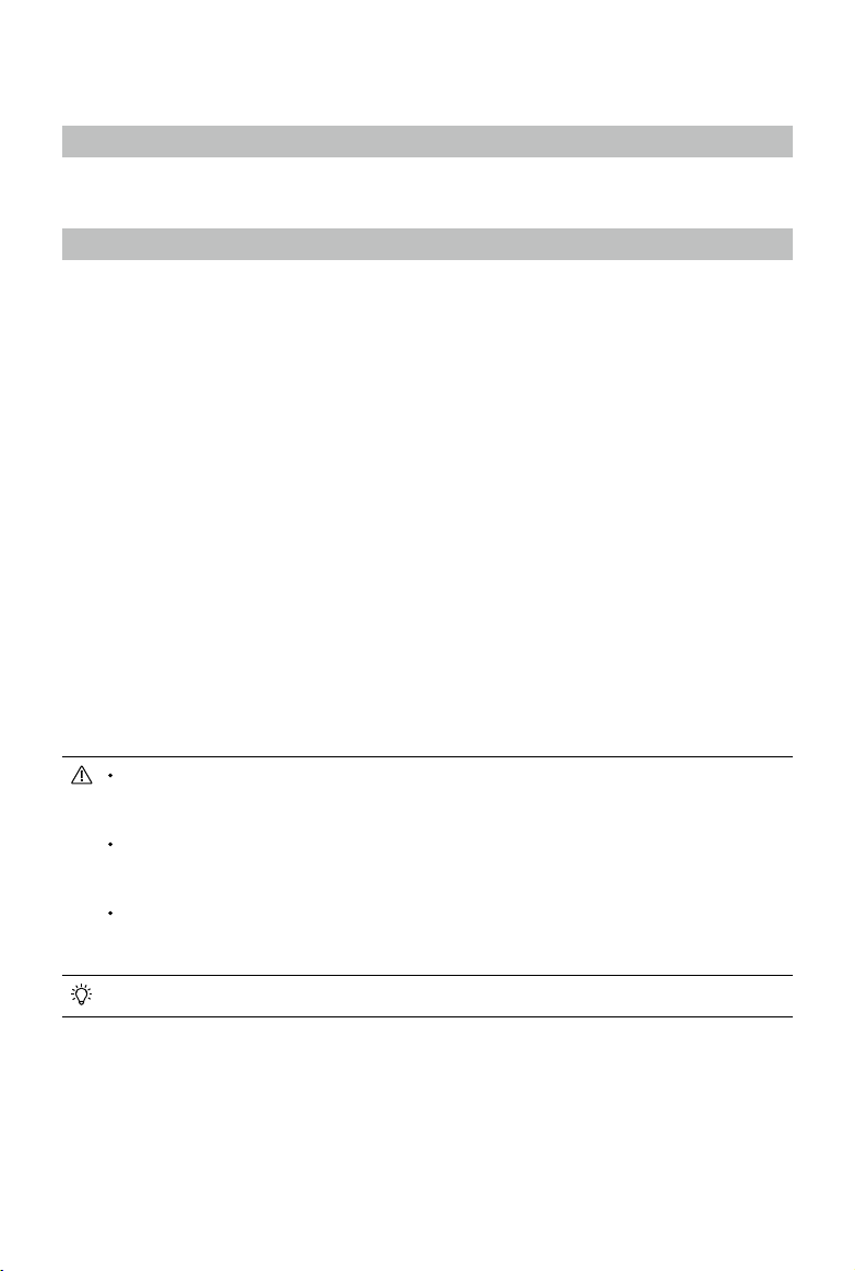
Flight Status Indicator
The aircraft features Front LEDs, Rear LEDs, and Aircraft Status Indicators. The positions of these
LEDs are shown in the gure below:
The Front LEDs show the orientation of the aircraft. Front LEDs glow solid red when the aircraft is
turned on to indicate the front (or nose) of the aircraft. Front and rear LEDs can be turned off in the DJI
Pilot app. The Aircraft Status Indicators communicate the system status of the ight controller. Refer to
the table below for more information about the Aircraft Status Indicators. The Front LEDs, Rear LEDs,
and Aircraft Status Indicators can be turned off in the DJI Pilot app for unobtrusive drone operations.
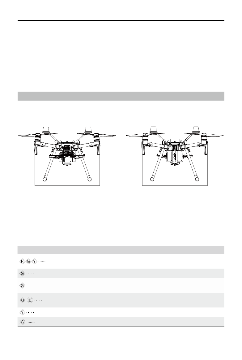
Aircraft Status Indicator Description
Normal
Red, green, and yellow
ashes
Turning On and Self Diagnostic Testing
Slow green ashing P-mode with GPS*
×2 Two green ashes
P-mode with Forward and Downward Vision
Systems*
Alternating green and
blue ashing
The RTK function of the M210 RTK V2 is enabled
and RTK data is used.
Slow yellow ashing A-mode (no GPS and vision positioning)
Fast green ashing Braking automatically after obstacle detected
Front LEDs
Aircraft
Status
Indicators
Rear LEDs
cannot position or auto-brake in this mode and is easily affected by its surroundings, which may
result in horizontal shifting. Use the remote controller to position the aircraft.
Maneuvering the aircraft in A-mode can be difcult. Before switching the aircraft into A-mode, make
sure you are comfortable ying in this mode. DO NOT y the aircraft too far away as you might lose
control and cause a potential hazard.
Avoid ying in areas where GPS signal is weak, or in conned spaces. The aircraft will otherwise be
forced to enter A-mode, leading to potential ight hazards, please land it in a safe place as soon as
possible.
* Slow green ashes indicate P-mode, and fast green ashes indicate S-mode.
©
2019 DJI All Rights Reserved.
17
MATRICE 200
SERIES V2 User Manual
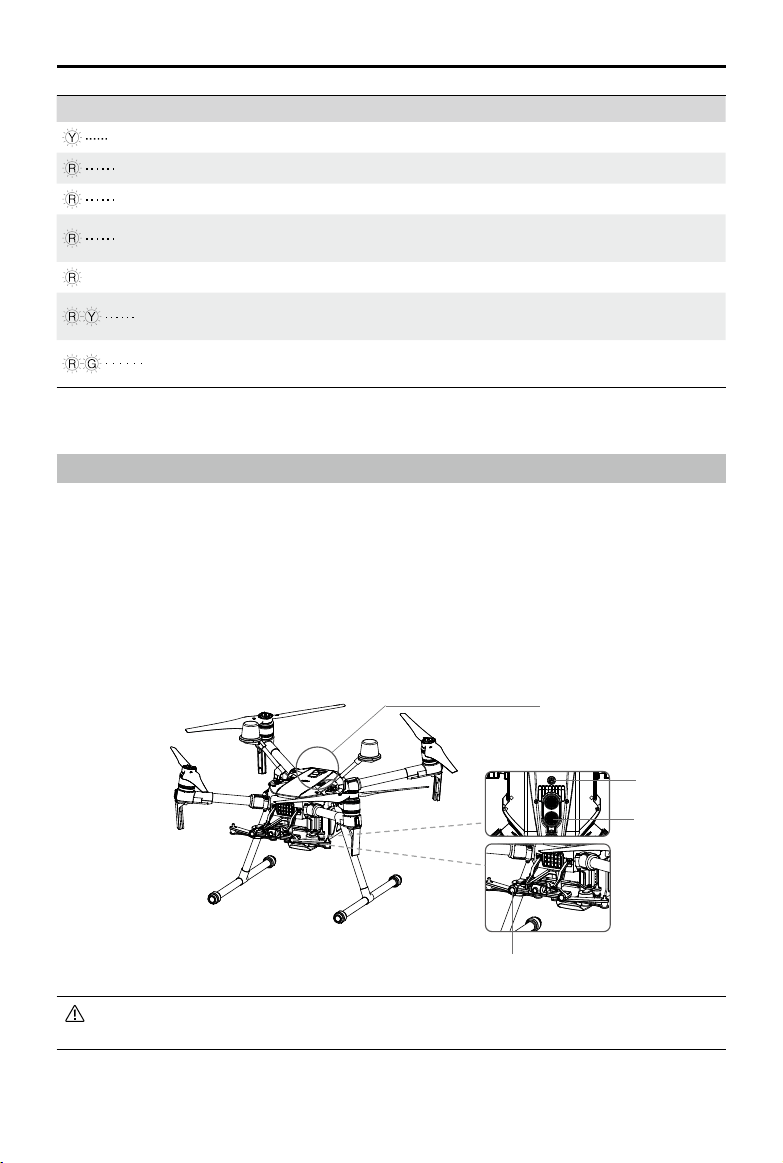
Warning
Fast yellow ashing Remote Controller Signal Lost
Slow red ashing Low Battery Warning
Fast red ashing Critical Low Battery Warning
Red ashing for 5 seconds
(when performing CSC)
IMU Error
—
Solid Red Critical Error
Fast alternating red and
yellow ashing
Compass Calibration Required
Alternating red and green
ashing
The RTK function of the M210 RTK V2 is enabled
but RTK data is unavailable.
To ensure steady ight and general ight safety, DO NOT block the visual and ultrasonic
sensors.
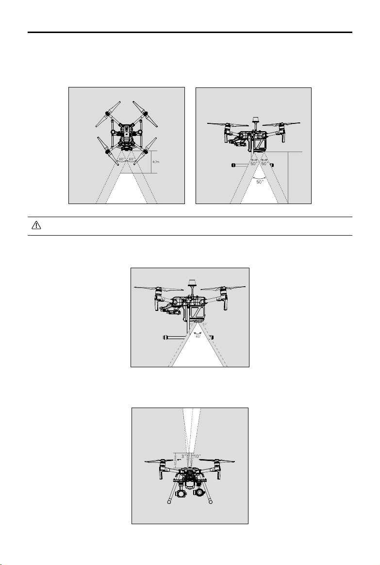
Vision System and Infrared Sensing System
The main components of the Vision System are located on the front and bottom of the aircraft, in-
cluding [1] [3] stereo vision sensors and [2] two ultrasonic sensors. The Vision Sys tem uses ultra-
sound and image data to help the aircraft maintain its current position, enabling precision hovering
indoors or in environments where a GPS signal is not available. The Vision System constantly scans
for obstacles, allowing the aircraft to avoid them by going over, going around, or hovering.
The Infrared Sensing System consists [4] of two infrared modules on top of the aircraft. These scan
for obstacles on top side of the aircraft and is active in certain ight modes.
[2]
[4]
[3]
[1]
18
©
2019 DJI All Rights Reserved.
MATRICE 200
SERIES V2 User Manual
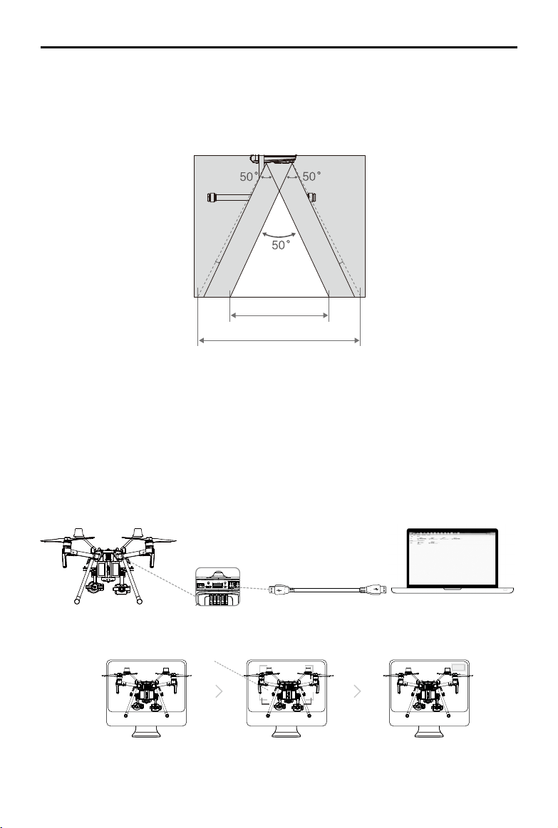
Detection Range
The detection range of the Vision System is depicted below. Note that the aircraft cannot sense and
avoid obstacles that are not within the detection range.
Infrared Sensing System detection range is depicted below.
The aircraft cannot detect objects in the grey area. Please y with caution.
Ultrasonic sensor detection range is depicted below.
10m
©
2019 DJI All Rights Reserved.
19
MATRICE 200
SERIES V2 User Manual
Calibration
The Vision System cameras installed on the aircraft are factory calibrated. If the aircraft experiences
a collision, however, it may require calibration via DJI Assistant 2 for Matrice. Connect the aircraft to
a computer and calibrate the Vision System cameras when prompted in DJI Pilot.
1. Power on the Intelligent Flight Battery and slide the USB Mode Switch right.
2. Connect the aircraft and the PC with a USB to USB cable. The USB extension cable included in
the package can be used if the USB to USB cable is too short for connection.
3. Launch DJI Assistant 2 for Matrice and log in with a DJI account.
4. Click M200 V2 SERIES and the calibration button.
1
Point the aircraft toward the screen
2
Align the boxes
3
Pan and tilt the aircraft
Follow the steps below to calibrate the camera.
A note on the vision system and the ultrasonic sensor detection range is illustrated below.
There may be a ±2° error in the angle of the downward vision system and ultrasonic sensor due
to errors in the assembly process. To prevent accidents, please DO NOT attach any payload that
might be in the sensors’ Do Not Obstruct Zone. If the payload comes into the Do Not Obstruct Zone,
it is recommended to turn off the downward vision system in the Pilot app and y with caution.
2º 2º
Effective Detection Range
Do Not Obstruct Zone
20
©
2019 DJI All Rights Reserved.
MATRICE 200
SERIES V2 User Manual
If using a laptop for calibration, it is recommended to remove the landing gear before
calibrating the downward vision system. Otherwise, the rectangle produced by the vision
system may not be aligned with the boxes on the screen as the aircraft is farther from the
screen.
DO NOT power off or unplug the USB cable after calibration. Wait for data calculation.
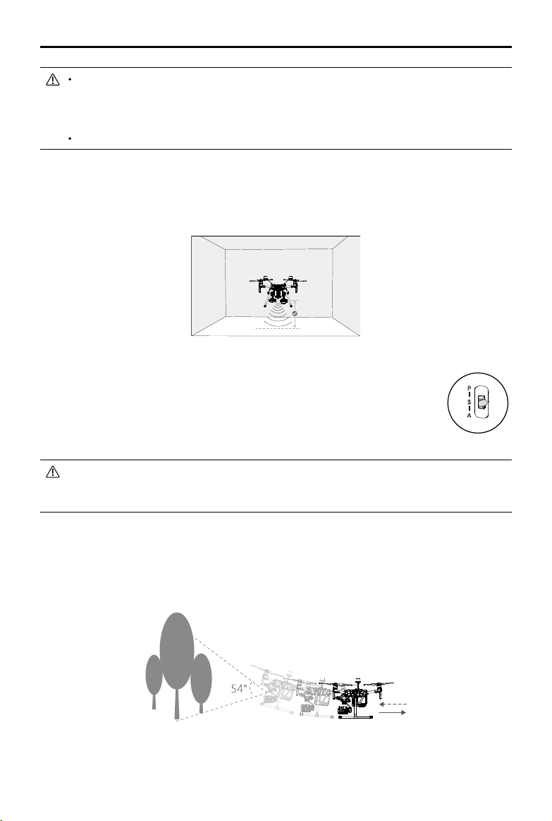
Using the Vision System
The Vision System is activated automatically when the aircraft is turned on. No further action is
required. The Downward Vision System enables precision hovering indoors or in environments where
GPS signal isn't available.
Follow the steps below to use the Downward Vision System:
1. Ensure the aircraft is in P-mode and place the aircraft on a at surface. Note
that the Downward Vision System cannot work properly on surfaces without
clear pattern variations.
2. Turn on the aircraft. The aircraft will hover in place after takeoff. The aircraft
status indicators will ash green twice, which indicates the Downward Vision
System is working.
If the downward vision system shuts down or is blocked by other objects, the aircraft will not
be able to hover at a low altitude indoors and the Landing Protection Function that controls
the landing speed will be disabled. Note: the aircraft may be damaged by landing too fast.
Assisted Braking from Obstacle Sensing
Powered by the Forward Vision System, the aircraft is able to actively brake when obstacles are
detected in front. Obstacle Sensing works best when lighting is adequate and the obstacle is
clearly textured. The aircraft must y at no more than 34 mph (54 kph) with a maximum pitch angel
of 25° to allow for sufcient braking distance.
Using Infrared Sensing System
The Infrared Sensing System can only be used to avoid large, diffuse, and reflective obstacles
(reectivity >10%). Please be mindful of blind spots (Grey) of the Infrared Sensing System.
10 m
©
2019 DJI All Rights Reserved.
21
MATRICE 200
SERIES V2 User Manual
The performance of your Vision System and Infrared Sensing System is affected by the surface
being own over. Ultrasonic sensors may not be able to accurately measure distances when
operating above sound-absorbing materials and the cameras may not function correctly in
suboptimal environments. The aircraft will switch from P-mode to A-mode automatically if neither
GPS nor Vision System and Infrared Sensing System are available. Operate the aircraft with
great caution in the following situations.
The Vision System will be disabled when:
a) Flying over monochrome surfaces (e.g. pure black, pure white, pure red, pure green).
b) Flying over highly reective surfaces.
c) Flying over water or transparent surfaces.
d) Flying over moving surfaces or objects.
e) Flying in an areas where the lighting changes frequently or drastically.
f) Flying over extremely dark (lux < 15) or bright (lux > 100,000) surfaces.
g) Flying over surfaces without clear patterns or texture.
h) Flying over surfaces with identical repeating patterns or textures (e.g. tiling).
i) Flying at high speeds of over 31 mph (50 kph) at 2 meters or over 11 mph (18 kph) at
1 meter.
The Ultrasonic sensors will be disabled when:
a) Flying over surfaces that can absorb sound waves (e.g. thick carpet).
b) Flying over inclined surfaces that will deect sound waves away from the aircraft.
The Infrared be disabled when:
a) Flying over obstacles with too small effective infrared reective surface.
b) DO NOT cover the protective glass of the infrared module. Keep it clean and undamaged.
Keep sensors clean at all times. Dirt or other debris may adversely affect their effectiveness.
Vision System is only effective when the aircraft is at altitudes of 0.3 to 10 meters.
The Vision System may not function properly when the aircraft is ying over water.
The Vision System may not be able to recognize pattern on the ground in low light
conditions (less than 100 lux).
Do not use other ultrasonic devices with frequency of 40 KHz when Vision System is in
operation.
Keep away from animals while operating the aircraft, as the ultrasonic sensors emit high-
frequency sounds which may disturb them.
Return-to-Home (RTH)
The Return-to-Home (RTH) function brings the aircraft back to the last recorded Home Point when
there is a strong GPS signal. There are three types of RTH: Smart RTH, Low Battery RTH, and
Failsafe RTH. This section describes these three RTH types in detail.
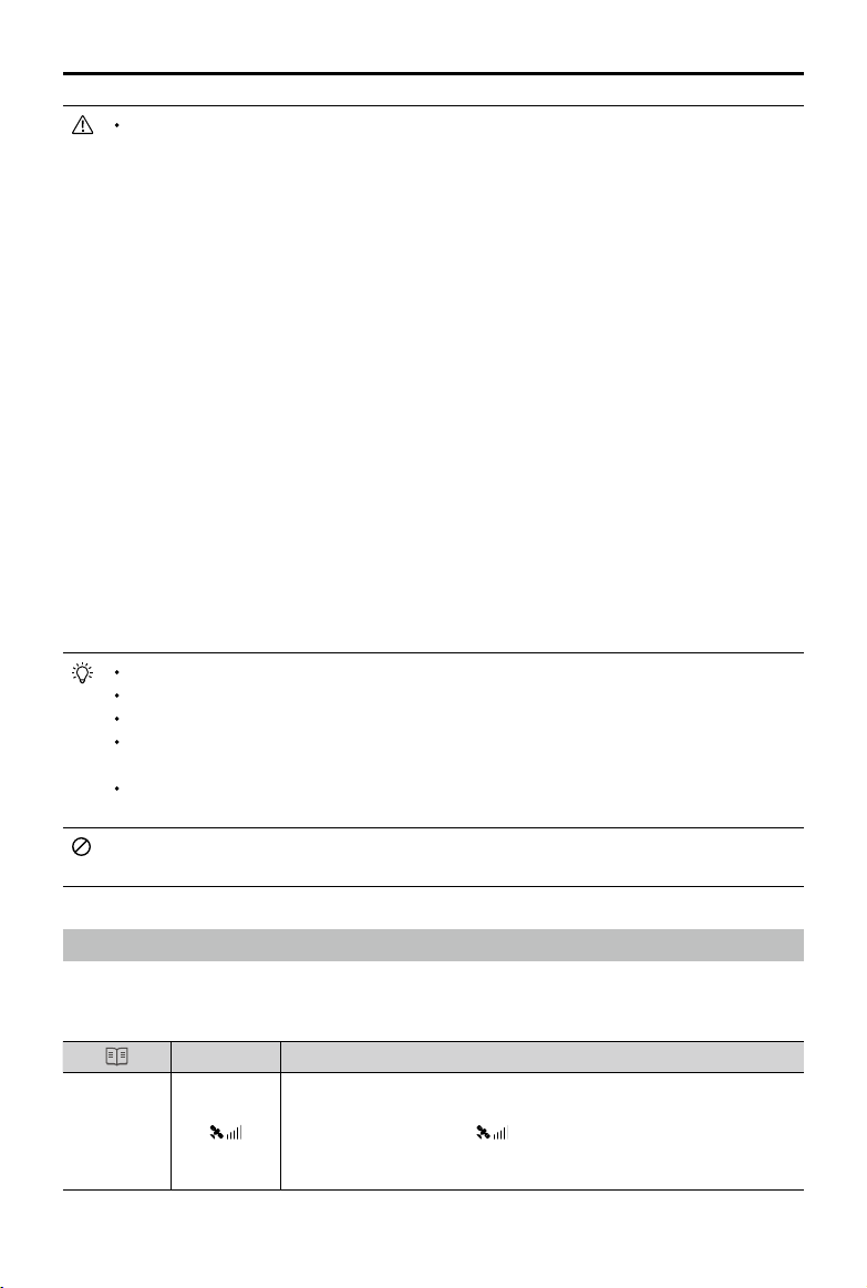
GPS
Description
Home Point
If a strong GPS signal was acquired before takeoff, the Home Point is
the location from which the aircraft launched. The GPS signal strength is
indicated by the GPS icon
. Less than 4 bars is considered a weak
GPS signal. The aircraft status indicator will blink green rapidly when the
home point is recorded.
22
©
2019 DJI All Rights Reserved.
MATRICE 200
SERIES V2 User Manual
The aircraft can sense and avoid obstacles when the Forward Vision System is enabled and
lighting conditions are sufcient. The aircraft will automatically ascend to avoid obstacles and
descend slowly as it returns to the home point. To ensure the aircraft returns home while facing
forward, it cannot rotate or y left and right during RTH while the Forward Vision System is
enabled.
Smart RTH
Use the RTH button on the remote controller and follow the on-screen instructions when GPS is
available to initiate Smart RTH. The aircraft will then automatically return to the last recorded Home
Point. Use the remote controller to control the aircraft’s speed or altitude to avoid a collision during
the Smart RTH process. Press and hold the Smart RTH button once to start the process, and press
the Smart RTH button again to terminate the procedure and regain full control of the aircraft.
Low Battery RTH (Can be turned off in DJI Pilot app)
The low battery level failsafe is triggered when the DJI Intelligent Flight Battery is depleted to a point
that may affect the safe return of the aircraft. Users are advised to return home or land the aircraft
immediately when prompted. The DJI Pilot app will display a notice when a low battery warning is
triggered. The aircraft will automatically return to the Home Point if no action is taken after a ten-
second countdown. The user can cancel the RTH procedure by pressing the RTH button on the
remote controller. The thresholds for these warnings are automatically determined based on the
aircraft’s current altitude and distance from the Home Point. If the RTH procedure is cancelled
following a low battery level warning the Intelligent Flight Battery may not have enough charge for
the aircraft to land safely, which may lead to the aircraft crashing or being lost.
The aircraft will land automatically if the current battery level can only support the aircraft long
enough to descend from its current altitude. The user cannot cancel the auto landing but can use
the remote controller to alter the aircraft’s orientation during the landing process.
The Battery Level Indicator is displayed in the DJI Pilot app, and is described below:
12:29
Remaining ight time
Sufcient battery
level (Green)
Battery level Indicator
Power required to
return home (Yellow)
Critical Low battery
level warning
Low battery
level warning
Auto landing (Red)
H
©
2019 DJI All Rights Reserved.
23
MATRICE 200
SERIES V2 User Manual
Battery
Level
Warning
Remark
Aircraft Status
Indicator
DJI Pilot App Flight Instructions
Low battery
level
warning
Battery power
is low. Land
the aircraft.
Aircraft status
indicator blinks
RED slowly.
Tap “Go-home” to
have the aircraft
return to the Home
Point and land
automatically, or
“Cancel” to resume
normal ight. If no
action is taken,
the aircraft will
automatically go
home after 10
seconds. Remote
controller will sound
an alarm.
If RTH is selected, the
aircraft will y back
to the Home Point
automatically and
Landing Protection*
will be triggered. Users
can regain control
during RTH. NOTE:
The low battery level
warning will not appear
again after users regain
control.
Critical Low
battery level
warning
The aircraft
must land
immediately.
Aircraft status
indicator blinks
RED quickly.
The DJI Pilot app
display will flash red
and the aircraft will
start to descend. The
remote controller will
sound an alarm.
Allow the aircraft to
descend automatically
and trigger Landing
Protection*.
Estimated
remaining
ight time
Estimated
remaining time is
based on current
battery level.
N/A N/A N/A
When the Critical Low battery level warning is triggered and the aircraft begins to land
automatically, push the left stick upward to make the aircraft hover at its current altitude,
giving you an opportunity to navigate to a more appropriate landing location.
The colored zones and markers on the battery level indicator bar reect the estimated
remaining ight time. They are automatically adjusted according to the aircraft’s current
location and status.
Failsafe RTH
If the Home Point was successfully recorded and the compass is functioning normally, Failsafe RTH
will be automatically activated if the remote controller signal is lost for more than three seconds.
The aircraft will plan its return route. The user may cancel Failsafe RTH to regain control when
connection is reestablished.
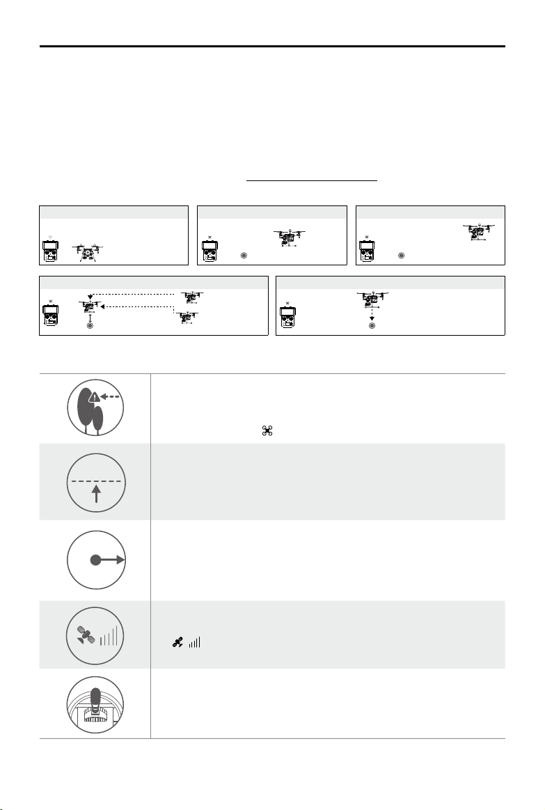
RTH Procedure
1. Home Point is recorded automatically.
* Make sure that the Downward Vision Positioning is enable in the DJI Pilot app.
24
©
2019 DJI All Rights Reserved.
MATRICE 200
SERIES V2 User Manual
2. RTH procedure is triggered i.e., Smart RTH, Low-Battery RTH, and Failsafe RTH.
3. Home Point is conrmed and the aircraft adjusts its orientation.
4. a. The aircraft will ascend to the pre-set RTH attitude and then y to the Home Point when the
aircraft is further than 20 m from the Home Point.
b. The aircraft will land automatically if RTH is triggered and the aircraft is less than 20 m from the
home point.
5. The aircraft will return to the Home Point, and Landing Protection* will be triggered to allow the
aircraft to land or hover in place. Refer to Landing Protection Function for details.
Use the Failsafe RTH for example:
Failsafe Safety Notices
20 m
20 m
H
RTH Altitude
The aircraft cannot avoid obstacles during Failsafe RTH when the
Forward Vision System is disabled. Therefore, it is important to set a
suitable Failsafe altitude before each flight. Launch the DJI Pilot app,
enter Camera and tap to set the Failsafe Altitude.
20 m
20 m
H
RTH Altitude
If the aircraft is ying under 65 feet (20 meters) and Failsafe (including
Smart RTH, Lower Battery RTH) is triggered, the aircraft will first
automatically ascend to 65 feet (20 meters) from the current altitude. You
can only cancel the ascending by exiting the Failsafe.
20 m
20 m
H
RTH Altitude
The aircraft automatically descends and lands if RTH is triggered when
the aircraft ies within a 65 foot (20 meter) radius of the Home Point. The
aircraft will stop ascending and immediately return to the Home Point if
you move the left stick when the aircraft is ying at an altitude of 65 feet (20
meters) or higher and Failsafe is triggered.
20 m
20 m
H
RTH Altitude
The aircraft cannot return to the Home Point when GPS signal is weak
( [
] displaying less than four bars) or is unavailable.
20 m
20 m
H
RTH Altitude
If you move the left stick when the aircraft is flying above 65 feet (20
meters) but below the pre-set Failsafe RTH altitude, the aircraft will stop
ascending and immediately return to the Home Point.
* Make sure that the Landing Protection is enable in the DJI Pilot app.
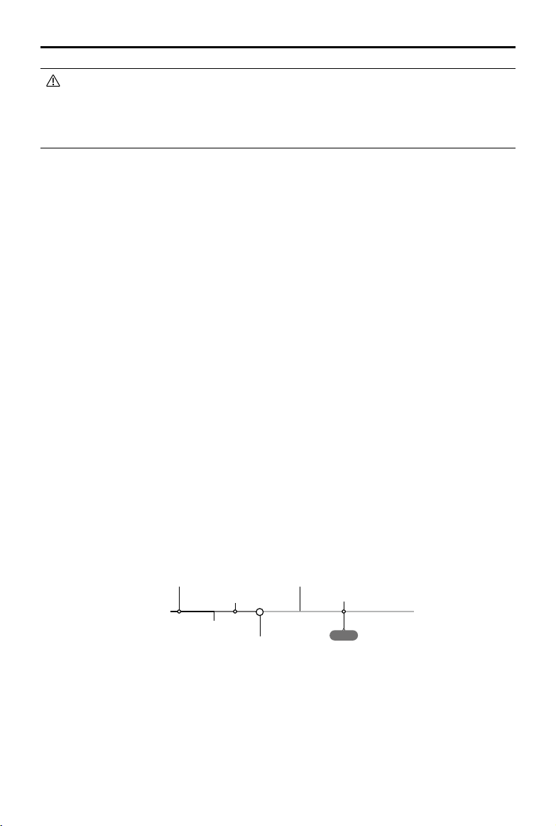
1. Record Home Point 2. Remote Control Signal Lost
5. Enter Landing Protection to land or hover
3. Signal Lost for Extended Time
4. RTH (Adjustable Altitude)
Height over HP<=Failsafe Altitude
Height over HP>Failsafe Altitude
Elevate to Failsafe Altitude
Failsafe Altitude
Hovering at 0.7 meters above the Home Point
©
2019 DJI All Rights Reserved.
25
MATRICE 200
SERIES V2 User Manual
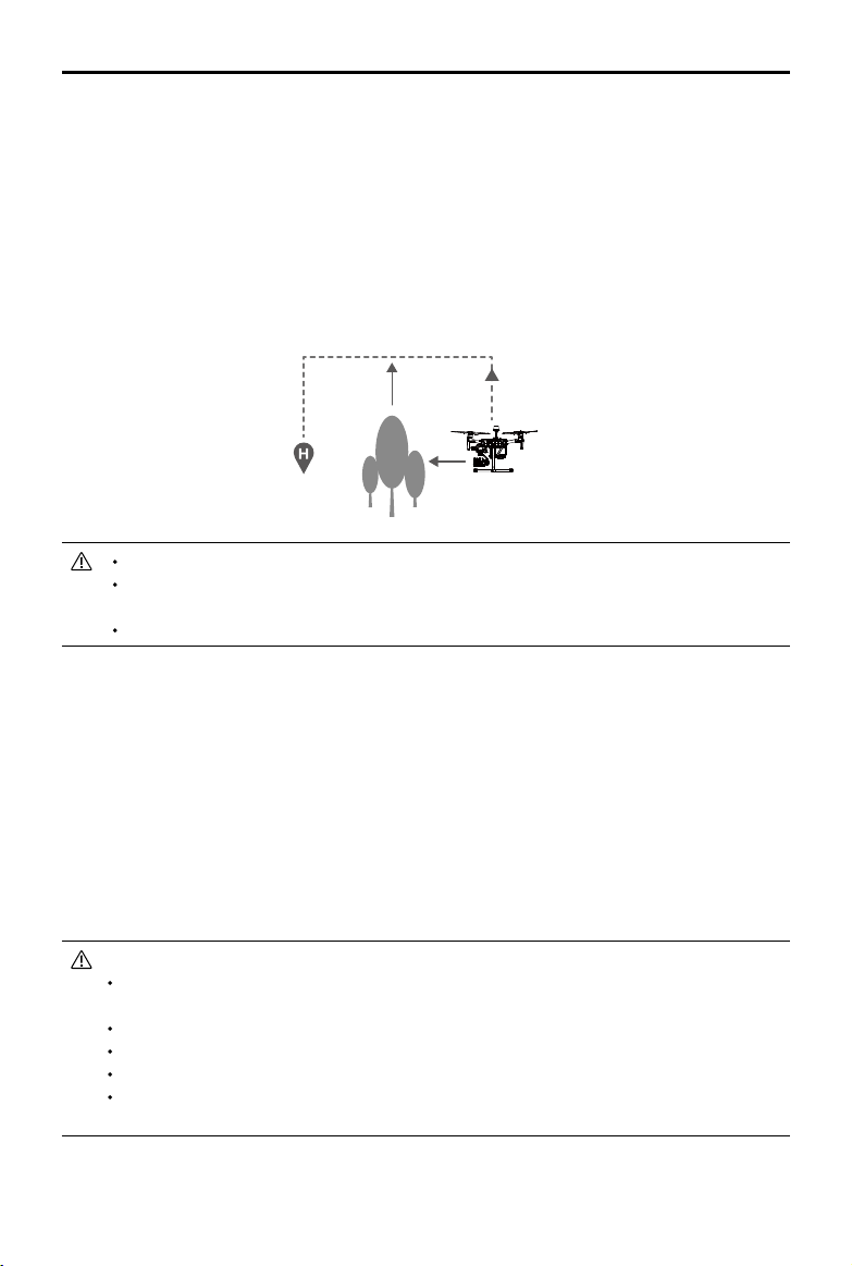
Obstacle Avoidance During RTH
The aircraft can sense and actively attempt to avoid obstacles during RTH, provided that lighting
conditions are adequate for the Forward Vision System. Upon detecting an obstacle, the aircraft will
act as follows:
1. The aircraft decelerates when an obstacle is sensed at approx. 49 feet (15 meters) ahead.
2. The aircraft stops and hovers then starts ascending vertically to avoid the obstacle. Eventually,
the aircraft will stop climbing when it is at least approx. 16 feet (5 meters) above the detected
obstacle.
3. RTH procedure resumes. The aircraft will continue ying to the Home Point at the current altitude.
Approx.
5 meters
Approx. 15 meters
Obstacle Sensing is disabled during RTH descent. Proceed with care.
To ensure the aircraft returns home forwards, it cannot rotate during RTH while the Forward
Vision System is enabled.
The aircraft cannot avoid obstacles beside or behind it.
Landing Protection Function
Landing Protection will activate during auto-landing.
1. Landing Protection determines whether the ground is suitable for landing. If so, the aircraft will
land smoothly.
2. If Landing Protection determines that the ground is not suitable for landing, the aircraft will hover and
wait for pilot conrmation. The aircraft will hover if it detects the ground is not appropriate for landing
even with a critically low battery warning. Only when the battery level decreases to 0% will the aircraft
land. Users retain control of aircraft ight orientation.
3. If Landing Protection is inactive, the DJI Pilot app will display a landing prompt when the aircraft
descends below 0.7 meters. Tap to conrm or pull down the control stick for 2 seconds to land when
the environment is appropriate for landing.
Landing Protection will not be active in the following circumstances:
When the user is controlling the pitch/roll/throttle sticks (Landing Protection will re-activate
when the control sticks are not in use)
When the positioning system is not fully functional (e.g. drift position error)
When the downward vision system needs re-calibration
When light conditions are not sufcient for the downward vision system
If an obstacle is within one meter of the aircraft, the aircraft will descend to 0.7m above the
ground and hover. The aircraft will land after user conrmation.
26
©
2019 DJI All Rights Reserved.
MATRICE 200
SERIES V2 User Manual
Center of Gravity Calibration
The center of gravity will shift when the aircraft payloads changes. To ensure stable flight, it is
required to recalibrate the aircraft’s center of gravity when a new payload is installed.
Calibrate in a windless environment. Make sure that the aircraft is hovering and there is a
strong GPS signal during calibration.
Maintain visual line of sight of the aircraft and pay attention to ight safety.
Calibration instructions: Go to Flight Controller Settings in the app, and tap Calibrate in the Center
of Gravity Auto Calibration section. The Aircraft Status Indicators will glow solid purple during
calibration. There will be a prompt in the app after calibration is completed.
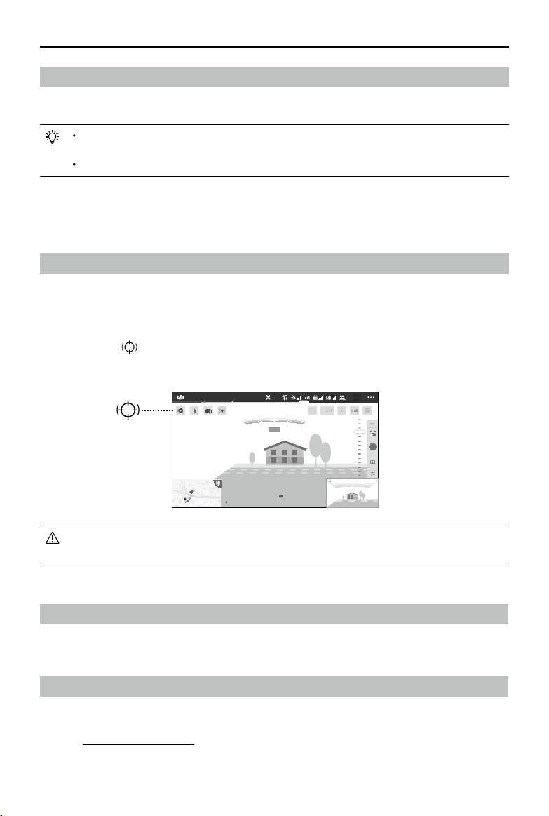
Spotlight Pro
Spotlight Pro is a powerful new tracking mode that allows a single pilot to capture complex,
dramatic images. The gimbal will automatically adjust to keep the camera pointing at the subject.
Lock onto a subject in Spotlight Pro mode and the gimbal will capture the locked subject regardless
of the directions that the aircraft ies.
Instructions: Tap
in Camera View in the app, and then use your nger to draw a square around
the object in to begin tracking.
You can drag on a subject in DJI Pilot or move the gimbal control sticks to change the
subject's position in the shot.
Flight Recorder
Flight data is automatically recorded to the internal storage of the aircraft. You can connect the
aircraft to a computer via the USB port and export this data via DJI Assistant 2.
Attaching and Detaching the Propellers
Attaching the Propellers
Refer to "Mounting the Propellers" for details.
1.5M
502 m
D 30 m
D
120 m
H 10 m
H
16.0 m/s
H.S 10.0 m/s
H.S
24.0 m/s
V.S 2.0 m/s
V.S
123456
2: 12: 45
123456
+ 147.498992, - 122.274800 113.95357, 22.54268
19:29
AF
/MF
74%
74%
4.07V
4.07V
AE
P-GPS
2.4G
In Flight (GPS)
©
2019 DJI All Rights Reserved.
27
MATRICE 200
SERIES V2 User Manual
Detaching the Propellers
Press the propeller down onto the mounting plate and rotate it in the unlock direction.
Propeller blades are sharp; please handle with care.
Only use DJI approved propellers. DO NOT mix propeller types.
Stay clear of spinning motors. DO NOT touch the propellers when they are spinning.
Ensure to check that the propellers and motors are installed rmly and correctly before
each ight.
Ensure that all propellers are in good condition before each ight. DO NOT use aged,
chipped, or broken propellers.
To avoid injury, stand clear of and DO NOT touch propellers or motors when they are
spinning.
Please use original DJI propellers for a better and safer ight experience.
DJI Intelligent Flight Battery
The TB55 Intelligent Flight Battery has a capacity of 7660 mAh, a voltage of 22.8 V, and a smart
charge/discharge functionality. The Intelligent Flight Battery must be fully charged before using it for
the rst time. It should only be charged using appropriate DJI approved chargers.
The battery rmware is included in the aircraft rmware. Make sure that all the batteries' rmware is
up-to-date.
DJI Intelligent Flight Battery Functions
1. Battery Level Display: The LED indicators display the current battery level.
2. Auto-Discharging: To prevent swelling, the battery automatically discharges to below 70% of the
total power when it is idle (press the power button to check that the battery level will cause the
battery to exit idle state) for more than 10 days to prevent swelling (can be set in app). It takes
around 11 days to discharge the battery to 65%. It is normal to feel moderate heat emitting from
the battery during the discharge process.
3. Balanced Charging: Automatically balances the voltage of each battery cell when charging.
4. Overcharge Protection: Charging automatically stops when the battery is fully charged.
5. Temperature Detection: The battery will not be charged to avoid damage when the battery
temperature is lower than 5 °C (41°F) or higher than 45°C (113°F).
6. Over Current Protection: The battery stops charging when a high amperage is detected.
7. Over Discharge Protection: Over-discharging can seriously damage the battery. Current output will
be cut off when the battery cell is discharged to 2.8 V when not in ight mode. For extended ight
times, over-charging protection is disabled as batteries discharge during ight. In this instance, a
battery voltage below 2 V may cause a safety hazard such as a re when charged. To prevent this,
the battery will not be able to charge if the voltage of a single battery cell is below 2 V. Avoid using
any batteries matching this description and avoid serious over-discharging to prevent permanent
battery damage.
8. Short Circuit Protection: Automatically cuts the power supply when a short circuit is detected.
9. Battery Cell Damage Protection: DJI Pilot displays a warning message when a damaged battery
cell is detected.
10. Sleep Mode: Sleep mode is entered to save power when the aircraft is not ying.
11. Communication: Information pertaining to the battery’s voltage, capacity, current, etc. is
transmitted to the aircraft’s main controller.
28
©
2019 DJI All Rights Reserved.
MATRICE 200
SERIES V2 User Manual
12. Heating: Batteries are able to work even in cold weather, ensuring a safe ight. Refer to "Using
the Battery" section for details.
13. Waterproof and Dustproof: The vehicle’s new airframe design improves the Ingress Protection
Rating to IP43 in accordance with the global IEC 60529 standards.
Refer to the
Disclaimer
and
Intelligent Flight Battery Safety Guidelines
before use. Users
take full responsibility for all operations and usage.
Charging the Intelligent Flight Battery
The Intelligent Flight Battery Charging Hub is designed for use with the Battery Charger. It charges
up to four Intelligent Flight Batteries simultaneously. The Charging Hub will intelligently charge
batteries in sequence according to battery power levels from high to low. The Micro USB port is
used for Charging Hub rmware updates.
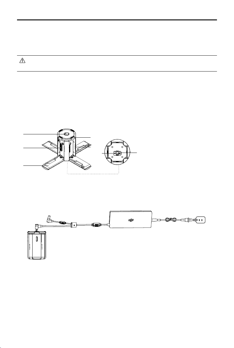
Overview
[3]
[1]
[2]
[8]
[6]
[5]
[4]
[7]
[1] Power Port
[2] Charging Port
[3] Charging Port Cover
[4] Battery Charging Level Indicators
[5] Cover/Battery Release Button
[6] Status LEDs
[7] Firmware Update Port (Micro USB)
[8] Buzzer Switch
Connecting to a Power Source
Connect the standard Battery Charger to a power outlet (100-240 V, 50/60 Hz), then uncover the
rubber cover on the power port to connect the Charging Hub to the Battery Charger*.
Power OutletChargerCharging Hub
* It will take approximately 2.5 hours to fully charge the TB55 Intelligent Flight Battery, and 2 hours for the remote
controller. It will take a longer time to charge the Intelligent Flight Battery and remote controller together.
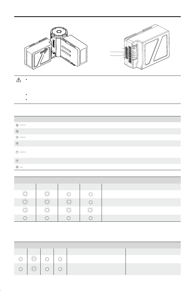
Connecting Batteries
Press the release button and open the corresponding charging port cover. Insert the Intelligent
Flight Battery into the charging port to begin charging. The Charging Hub will intelligently charge
batteries in sequence according to battery power levels from high to low. Refer to the "Status LED
Description” section for more information about Status LED blinking patterns. The buzzer will begin
beeping when charging is complete. Refer to the “Buzzer Beeping Description” for more information
about buzzer beeping patterns.
©
2019 DJI All Rights Reserved.
29
MATRICE 200
SERIES V2 User Manual
LED1
LED3
Battery Level Button
LED2
LED4
Always align the grooves on the Intelligent Flight Battery with the battery slot tracks. Make
sure the Status LED of the Charging Hub has a blinking pattern of charging or ready to
charge indicating that the battery is inserted correctly.
Press the release button to detach batteries after charging is complete.
DO NOT leave metal terminals exposed to open air when not in use.
Status LED Descriptions
Status LED (Charging Hub) Description
Blinks Green Charging
— Solid Green Fully charged
Blinks Red Battery Charger Error. Retry with an ofcial battery charger.
— Solid Red Intelligent Flight Battery error
Blinks Yellow
Battery temperature too high/low. Temperature must be within
operating range (5°-40
℃
)
— Solid Yellow Ready to charge
Alternating Green Blinks Intelligent Flight Battery not detected
Battery Level Indicators while Charging (Battery)
LED1 LED2 LED3 LED4 Battery Level
0%~50%
50%~75%
75%~100%
Fully Charged
Charging Protection LED Display
The table below shows battery protection mechanisms and corresponding LED patterns.
Battery Level Indicators for Battery Protection
LED1 LED2 LED3 LED4 Blinking Pattern Battery Protection Item
LED2 blinks twice per second Over current detected
LED2 blinks three times per
second
Abnormal battery cell voltage
detected
30
©
2019 DJI All Rights Reserved.
MATRICE 200
SERIES V2 User Manual
LED3 blinks twice per second Over charge detected
LED3 blinks three times per
second
Over-voltage charger detected
LED4 blinks twice per second
Charging temperature is too
low (<0°C)
LED4 blinks three times per
second
Charging temperature is too
high (>40°C)
After any of the above mentioned protection issues are resolved, press the button to turn off the
Battery Level Indicator. Unplug the Intelligent Flight Battery from the charger and plug it back in to
resume charging. Note that you do not need to unplug and plug the charger in the event of a room
temperature error, the charger will resume charging when the temperature falls within the normal
range.
DJI does not take any responsibility for damage caused by third-party chargers.
To ensure safety, discharge the battery before transporting the aircraft. Fly the aircraft out-
doors until its power level is lower than 30%.
The battery has a capacity of 174.6 Wh. Please follow the regulations and guidelines for
traveling with these batteries via air.
Buzzer Beeping Description
Toggle the buzzer switch to turn on/off the warning sound.
Descriptions Beeping Pattern
Toggle the buzzer switch to turn it on Quick beeping
Connect to the Battery Charger Quick beeping
A battery pair is fully charged Quick beeping
Four Intelligent Flight Batteries are fully charged
Alternating between two short and one
long beep, lasting for about 1 hour
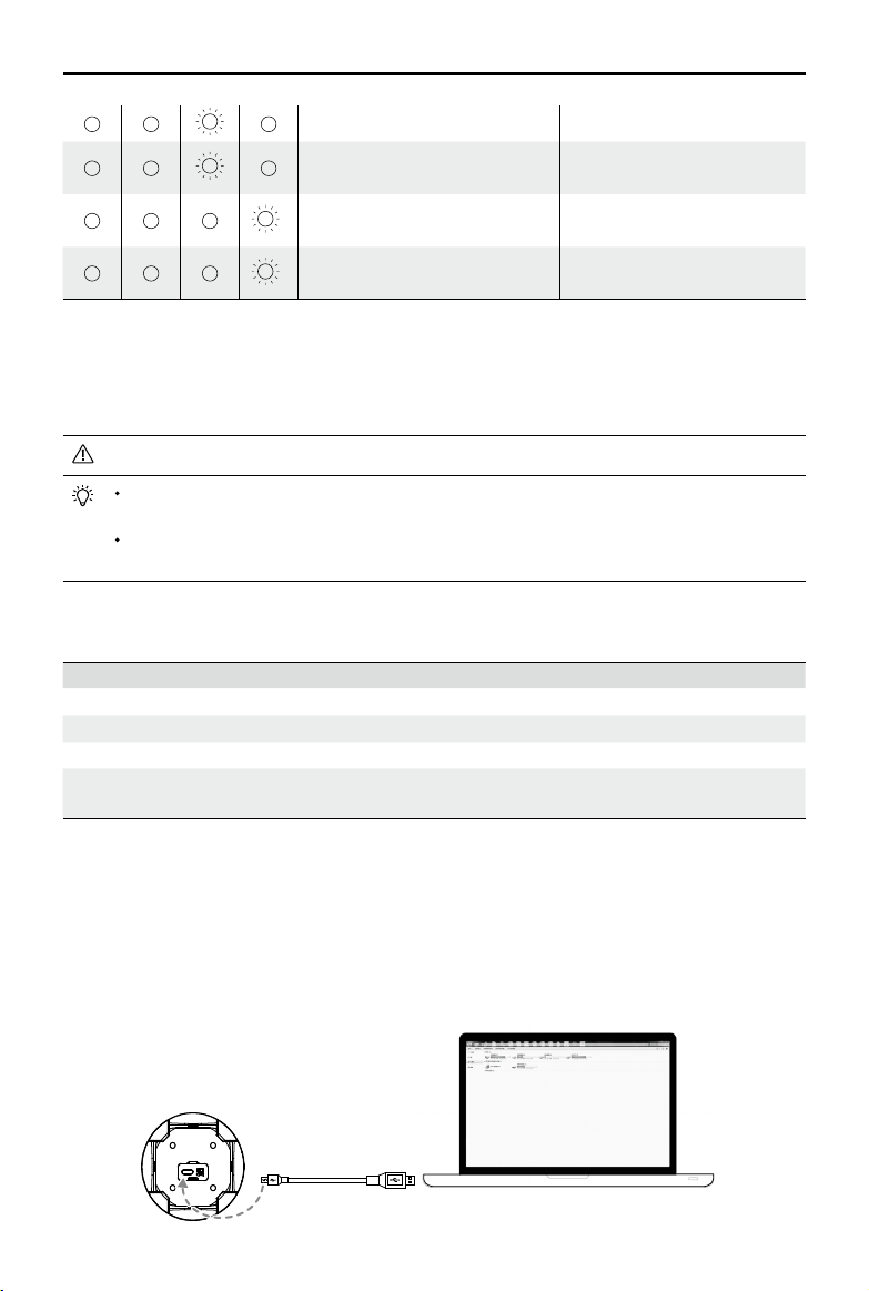
Updating the Firmware
DJI will release rmware updates when available. Refer to the ofcial DJI website and follow the
instructions below to update the rmware.
1. Download the latest rmware update program from the ofcial DJI website.
(http://www.dji.com/matrice-200-series-v2/info#downloads)
2. Turn on the Charging Hub, then connect it to a computer using a Micro USB cable.
©
2019 DJI All Rights Reserved.
31
MATRICE 200
SERIES V2 User Manual
3. Run the rmware update program. Press the update button and wait for the process to nish.
4. The Charging Hub will automatically restart when the update has been successfully completed.
5. Repeat this process if the rmware update fails for any reason.
Using the Battery
A
B
Low
High
Pairing Batteries
Before rst use, it is recommended to mark 2 batteries as a pair and continue using them as a pair
(charge and discharge them together) to maximize service life and ensure ight performance.
If two batteries with a signicant difference in battery life are installed and powered on, a prompt will
pop up in the app to recommend that you replace the batteries to a pair with similar performance.
Turning ON/OFF
Turning On: Press the Power button once, then press again and hold for two seconds to power on.
The Power LED will turn white and the Battery Level Indicators will display the current
battery level.
Turning Off: Press the Power button once, then press again and hold for two seconds to power off.
Heating the Battery
Manual Heating: If the Intelligent Flight Battery is not installed into the aircraft, press and hold the
battery level button on the battery for four seconds to initiate the self-heating, keeping the batteries
at a temperature between 61° F (16° C) and 68° F (20° C), which is the ideal range of operating
temperature, for approximately 30 minutes. Press and hold the battery level button for two seconds
to stop heating.
Auto Heating: Insert the batteries into the aircraft and power it on. If a low battery temperature is
detected, the battery will automatically heat up to maintain a temperature between 61° F (16° C)
and 68° F (20° C).
Low Temperature Notice:
1. The performance of the intelligent Flight Battery is significantly reduced when flying in low
temperature environments (temperatures below 5℃). Ensure that the battery is fully charged and
the cell voltage is at 4.35 V before each ight.
2. End the ight as soon as DJI Pilot displays the “Low Battery Level Warning” in low temperature
environments. You will still be able to control the aircraft’s movement when this warning is
triggered.
3. In extremely cold weather, the battery temperature may not be high enough even after warming
up. In these cases, insulate the battery as required.
4. To ensure optimal performance of the battery, keep the battery temperature above 16℃.
5. In low temperature environments, it will take a longer time for the batteries to warm up. It is
recommended to keep the battery warm before use to reduce the warm-up time.
32
©
2019 DJI All Rights Reserved.
MATRICE 200
SERIES V2 User Manual
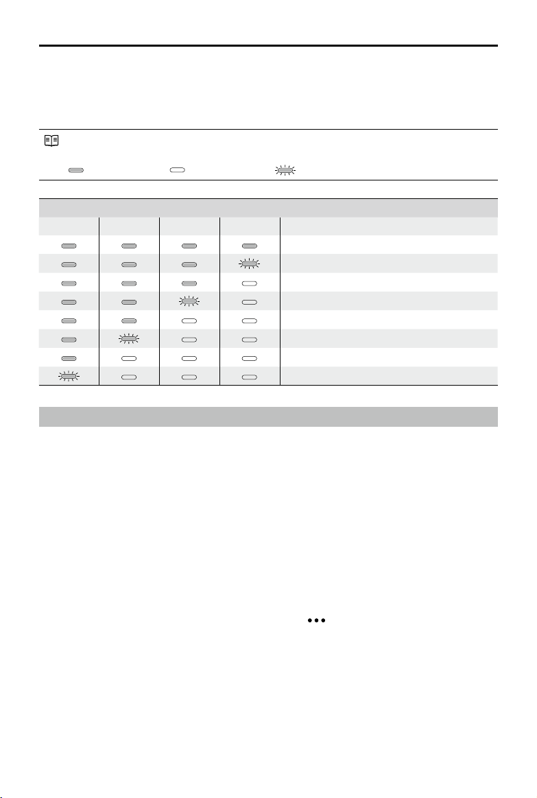
Checking Battery Levels
Battery Level Indicators display how much power remains. When the battery is turned off, press the
Power button once and the Battery Level Indicators LEDs will display the current battery level. See
below for details.
The Battery Level Indicators will also show the current battery level during discharging. The
indicators are dened below.
: LED is on. : LED is off.
: LED is ashing.
Battery Level
LED1 LED2 LED3 LED4 Battery Level
88%~100%
75%~88%
63%~75%
50%~63%
38%~50%
25%~38%
13%~25%
0%~13%
D-RTK (for M210 RTK V2)
Introduction
The M210 RTK V2 aircraft has a built-in DJI Onboard D-RTK 2, which can withstand magnetic
interference from metal structures, ensuring stable ight. More accurate positioning data can be
achieved when using a DJI D-RTK 2 High Precision GNSS Mobile Station for Matrice Series. If the
RTK signal is weak and differential data cannot be transmitted during ight, users can read the
raw satellite observations* recorded in the aircraft after the ight, and then use PPK technology to
achieve centimeter-level positioning.
* The raw satellite observations will be recorded when the RTK function is enabled on the aircraft and the search for satellites
is nished. Connect the aircraft to a computer to obtain the observations in the directory \rtk_data\rtk_rtcm in the removable
disk corresponding to the aircraft.
Enable/Disable RTK
Ensure that the “Aircraft RTK” is enabled and RTK service type is correctly set (D-RTK 2 Mobile
Station) before each use. Go to Camera View in the app > > RTK to view and set.
Make sure to disable RTK function if not in use. Otherwise, the aircraft will not be able to take off
when there is no differential data.
Using with the DJI D-RTK 2 Mobile Station
1. Refer to the D-RTK 2 Mobile Station for Matrice Series User Guide to complete linking between
the aircraft and the mobile station and setup of the mobile station.
2. Power on the mobile station and wait for the system to start searching for satellites. In the RTK
Settings page in the app, the status of both the aircraft’s orientation and positioning in the status
table will show “FIX” to indicate that the aircraft has obtained and used the differential data from
the mobile station.

©
2019 DJI All Rights Reserved.
33
MATRICE 200
SERIES V2 User Manual
DJI AirSense
Airplanes and helicopters with an ADS-B transceiver will actively broadcast flight information
including location, ight path, speed, and altitude. DJI AirSense receives this by ADS-B transceivers
via an on-board receiver or internet connection. UAVs installed DJI AirSense can obtain the position,
orientation and velocity information from the manned airplane built-in ADS-B transmitter (1090 ES
and UAT standard supported), calculate the collision risk level real time and send the warning to
user. The system will analyze the potential risk of collision by comparing the location of an airplane
or a helicopter, sending timely warnings to pilots via the DJI Pilot app.
DJI AirSense provides users with information about nearby airplanes and helicopters to ensure ight
safety. The system doesn’t actively control the drone to avoid incoming airplanes or helicopters.
Always y your aircraft within a visual line of sight and be cautious at all times. Lower your altitude
when you receive warnings. Please be aware that DJI AirSense has the following limitations:
1. It can only receive messages sent by airplanes and helicopters installed with an ADS-B out
device and in accordance with 1090ES (RTCA DO-260) or UAT (RTCA Do-282) standards.
DJI devices will not receive related broadcast messages or send out warnings for airplanes or
helicopters without ADS-B outs or with malfunctioning ADS-B outs.
2. If there is an obstacle or steel structure between airplanes or helicopters and DJI aircraft, the
system won’t be able to receive ADS-B messages sent by airplanes or helicopters or send out
warnings. Keenly observe your surroundings and y with caution.
3. Warnings may be sent with delay when the DJI AirSense is interfered by the surrounding. Keenly
observe your surroundings and y with caution.
4. Warnings are not sent when a DJI aircraft is unable to determine its location.
5. It cannot receive ADS-B messages sent by airplanes or helicopters or send out warnings when
disabled or miscongured.
On the precondition that connection between a DJI aircraft and the pilot remote controller is stable,
when the system conrms the possibility of a collision, it will send a series of warnings based on the
distance between drone and airplanes or helicopters. We recommended that the operator descend
altitude immediately after the rst warning to avoid a collision, choosing another ight path where
necessary.
Warning Escalation:
The rst (or "lowest") level warning occurs three minutes away from the airplanes or helicopters.
The second (or “middle”) level warning occurs two minutes away from the airplanes or helicopters.
The third (or “highest”) level warning occurs one minute away from the airplanes or helicopters.
Red: The third level warningBlue: The rst level warning Yellow: The second level warning
34
©
2019 DJI All Rights Reserved.
MATRICE 200
SERIES V2 User Manual
Extended Power Port (XT30)
Used to supply power for other device, whose voltage range is from 18 V to 26 V (the voltage
varies according to the aircraft battery level) with a current of 4 A. Make sure your device meets the
voltage and current requirement. The use of a device with a power that exceeds the maximum may
affect ight performance adversely or even cause aircraft damage.
USB Mode Switch
Power on the Intelligent Flight Battery and slide the USB Mode Switch right, and connect the USB
port on the aircraft to the computer via the USB to USB cable included in the package. Once
connected, you can access photos and videos in the microSD card (for the X4S, X5S, and X7), ight
records or congure aircraft parameters and run rmware updates using the DJI Assistant 2 for
Matrice. OSDK devices can also be connected to the USB port when the switch is slid to the right.
USB Port
The USB port is used to connect to a computer or OSDK devices. The corresponding devices can
be connected when the USB mode switch is slid to different positions. The USB port can supply
power with a maximum voltage of 5V and maximum current of 1A when the switch is slid to the left.
Linking Button and Indicator
Used to link between aircraft and remote controller, and the built-in LED will display the linking
status during linking procedure.
Expansion Ports
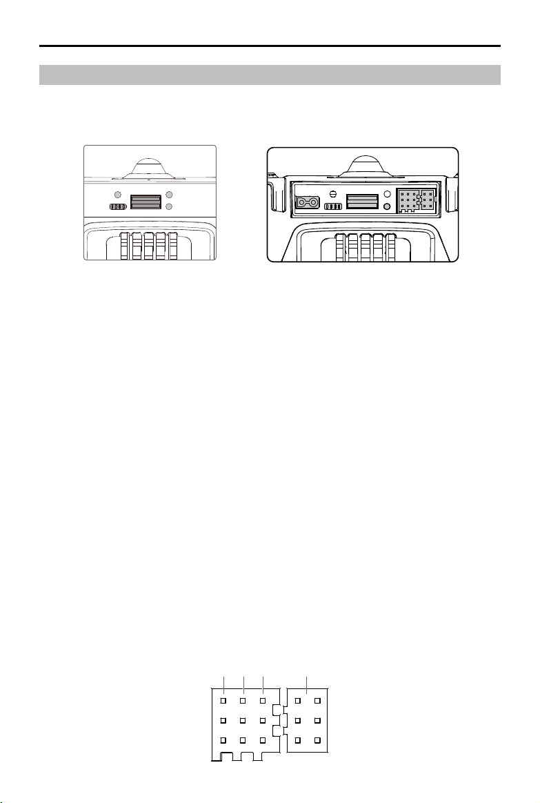
Components at the Rear of the Aircraft
M210 V2/M210 RTK V2 provides several I/O ports, which can be customized in the DJI Pilot app.
The aircraft also has components such as Extended Power Port, USB Mode Switch, Linking Button,
and USB Port.
1 2 3 4
M210 V2 / M210 RTK V2M200 V2*
* Note that the M200 V2 only has USB Mode Switch, Linking Button, and USB Port.
©
2019 DJI All Rights Reserved.
35
MATRICE 200
SERIES V2 User Manual
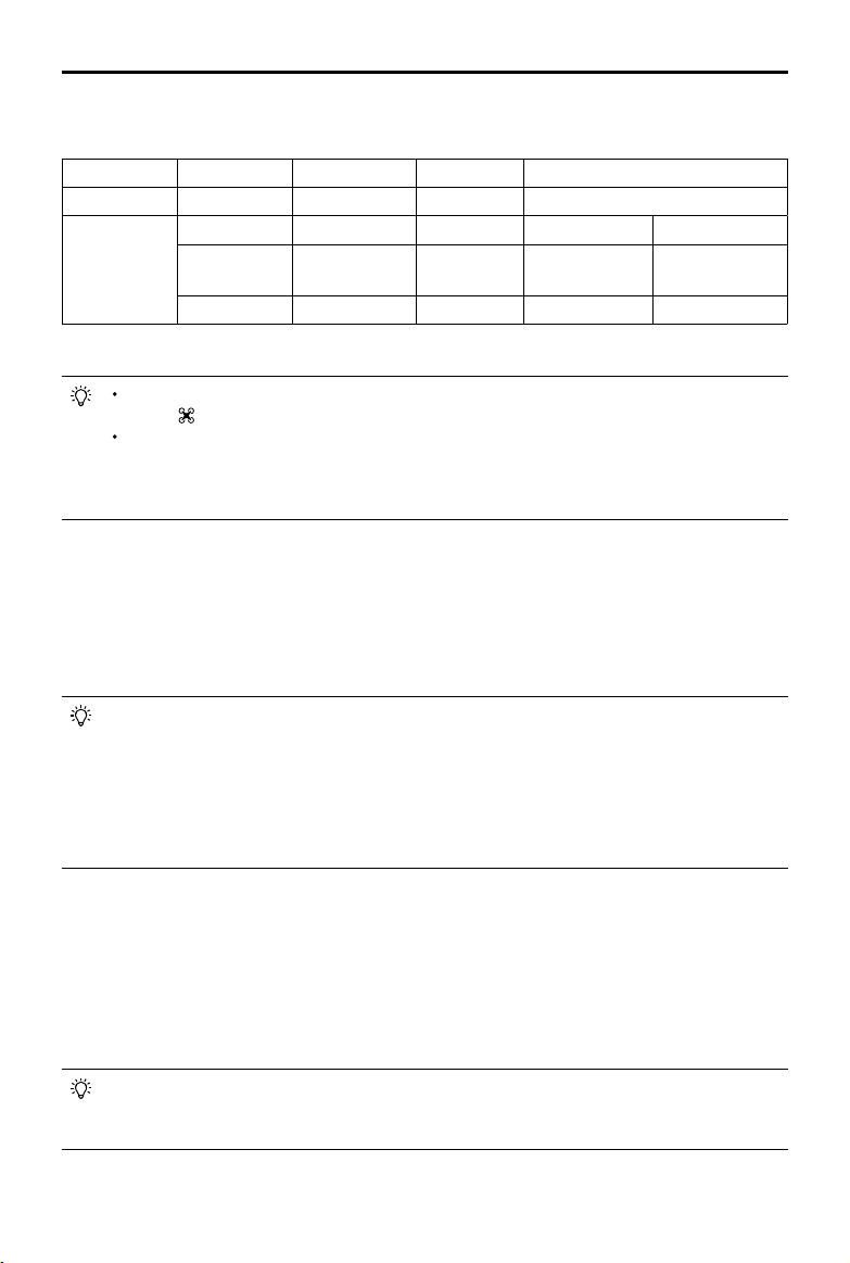
Pins Descriptions
PWM power level is 3.3V and all pins can be congured in DJI Pilot app.
Number 1 2 3 4
Name I/O port I/O port OSDK port Especially for an external GPS Kit*
Pins (from up
to down)
TIMESNYC GND GND / /
PWM3/GPIO3
PWM4/GPIO4/
HARDSYNC
SDK_RX / /
PWM1/GPIO1 PWM2/GPIO2 SDK_TX / /
* An external GPS Kit is required when a single upward gimbal or other payload is used on the M210 V2.
It is required to enable the expansion ports in the app before rst-time use. Go to Camera
View >
> Extended IO Conguration to set.
Make sure to install two batteries to the aircraft, power on the aircraft and wait for the
system to be ready when the power supply port is enabled in the app. Otherwise the
expansion ports cannot be used. When using in low-temperature environments, the
batteries must be preheated.
Usage of the TIMESYNC Pin
The TIMESYNC pin is for the TimeSync function. This function uses the PPS signal of the GPS
module or RTK module to synchronize the aircraft time to the UTC time, and provides the Onboard
SDK users with the precise UTC time of the rising edge of the TIMESYNC output pulse. Users
can apply this UTC timestamp to the data from their third-party payloads to achieve precise time
synchronization.
The TIME_SYNC pin provides output of the raw GPS and RTK data in GSA and RMC types
in the NMEA standard. For the M210 RTK V2 aircraft, if RTK is disabled, the output will be
the PPS signal of 5 Hz from the GPS module. If RTK is enabled, the output will be the PPS
signal of 5 Hz from the GPS module before the RTK module receives satellite data. Once
the RTK module receives satellite data, the output will always be the PPS signal of 1 Hz
from the RTK module. For the M210 V2 aircraft, the output will always be the PPS signal of 5
Hz from the GPS module.
Usage of the HARDSYNC Pin
The HARDSYNC pin is for the ight controller time synchronization function. This function uses the
synchronization hardware signal from the ight controller to synchronize the data from the aircraft’s
sensors (such as IMU, Vision System, camera) to the same clock source. It is an autonomous time
synchronization method that does not rely on external information so that it can achieve precise
ight controller time synchronization even in environment without satellite signals such as indoors or
area with building obstruction.
The HARDSYNC pin provides output of the data such as IMU data, images from the Vision
System, and camera data from the aircraft’s sensors. The output will start with a pulse
frequency of 20 Hz once the aircraft is powered on.
36
©
2019 DJI All Rights Reserved.
MATRICE 200
SERIES V2 User Manual
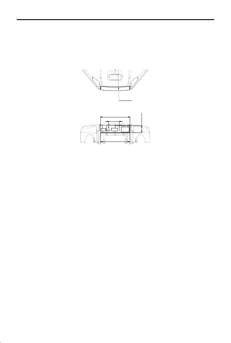
R238.06
23.18
15.11
63.51
64.02
This curve is similar to an arc with a radius of
238.06 mm.
Unit: mm
R238.06
23.18
15.11
63.51
64.02
Mounting the Waterproof Rear Port Cover (For M210 V2 / M210 RTK V2)
Users can customize a waterproof cover after connecting devices to the rear ports to ensure the
level of ingress protection.
First, remove the two screws in the rear of the aircraft and then remove the standard cover. Then
mount your own waterproof cover.
Top View
Rear View
Refer to the 3D model le on the ofcial DJI website for detailed dimensions.
Remote Controller
This section describes the features of the
remote controller that includes aircraft
and remote controller operations.
38
©
2019 DJI All Rights Reserved.
Remote Controller
Remote Controller Prole
The CENDENCE
TM
S remote controller features DJI’s OcuSync 2.0 technology for a maximum
transmission distance of up to 5 mi (8 km).* Equipped with a DJI CrystalSky 7.85 inch ultra-bright
monitor, it displays a HD live view directly via the built-in DJI Pilot app, providing a precise and
responsive flying experience. Or equipped with a mobile device with a mobile device holder to
download the DJI Pilot app. Dual frequency* support makes the HD video downlink more stable. In Dual
Remote Controller Mode, two remote controllers control the aircraft and camera separately, even when
they are up to 656 feet (200 m) apart.*
The remote controller works with a WB37 Intelligent Battery, which can be fully charged via the charging
port in about 2 hours with the standard charger, or with the Intelligent Battery Charging Hub in about 1
hour and 11 minutes. The maximum run time of the remote controller is approximately 4 hours without
supplying power to a monitor and with Dual Remote Controller mode disabled.*
* The remote controller can reach its maximum transmission distance (FCC) in an unobstructed area with
no electro-magnetic interference at an altitude of about 400 feet (120 meters). The actual maximum
transmission distance may be less than the distance mentioned above due to interference in the operating
environment, and the actual value will uctuate according to the strength of interference.
Note that the CrystalSky is excluded in the M200 V2.
To comply with local regulations, the 5.8 GHz frequency is not available in some countries and regions.
The Dual Remote Controller mode will be supported later.
Maximum run time is estimated in a lab environment without supplying power to a smart device or monitor,
for reference only.
Compliance Standards: The remote controller is compliant with local laws and regulations.
Stick Mode: Controls can be set to Mode 1, Mode 2, or to a custom mode.
Mode 1: The right stick serves as the throttle.
Mode 2: The left stick serves as the throttle.
Please refer to the CrystalSky User Guide for more CrystalSky details.
Do not operate more than three aircraft within the same area (roughly the size of a soccer
eld) to prevent transmission interference.
Preparing the Remote Controller
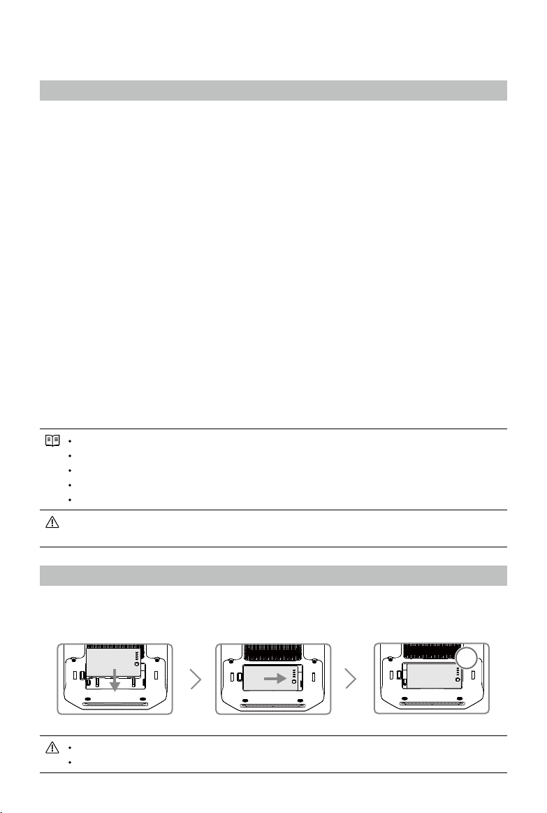
Mounting/Removing the Intelligent Battery
Put the battery into the Battery Slot, then slide it to the end until you hear a click.
OK
Press the Battery Release Button before removing the battery.
Press the Battery Level Button once to check the battery level.
©
2019 DJI All Rights Reserved.
39
MATRICE 200
SERIES V2 User Manual
Charging the Battery
The remote controller is powered by a WB37 intelligent battery, which can be charged via the
charging port or by the WCH2 Intelligent Battery Charging Hub.
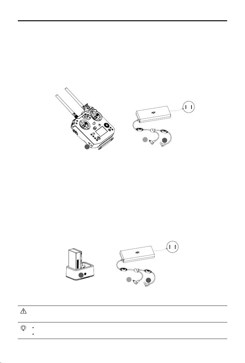
Using the Charging Port
Place the battery into the remote controller, and connect connector B of the battery power port, then
connect the battery charger to a power outlet (100-240V, 50/60Hz). When charging is complete, the
display on the remote controller will show 100%.
B
B
A
Power Qutlet
100~240 V
Charging Time: 2 hours
Using the Charging Hub
Place the battery into the Charging Hub, and connect connector B of the battery charger to
the charging hub, then connect the battery charger to a power outlet (100-240V, 50/60Hz). The
Charging Hub will intelligently charge batteries in sequence according to battery power levels from
high to low. The buzzer will begin beeping when charging is complete. Remove the battery or turn
off the Buzzer Switch to stop it.
The charging hub blinks green while charging and turns solid green when charging is nished.
B
A
B
Power Qutlet
100~240 V
Using the WCH2 Charging Hub, charging time is approximately 1 hour and 11 minutes (for one battery).
Place the battery into the Charging Hub, and connect connector B of the battery charger to
the charging hub, then connect the battery charger to a power outlet (100-240V, 50/60Hz).
USB power supply port can be used to charge the mobile device of 5V/2A.
Refer to the WCH2 Charging Hub User Guide for more details.
B
40
©
2019 DJI All Rights Reserved.
MATRICE 200
SERIES V2 User Manual
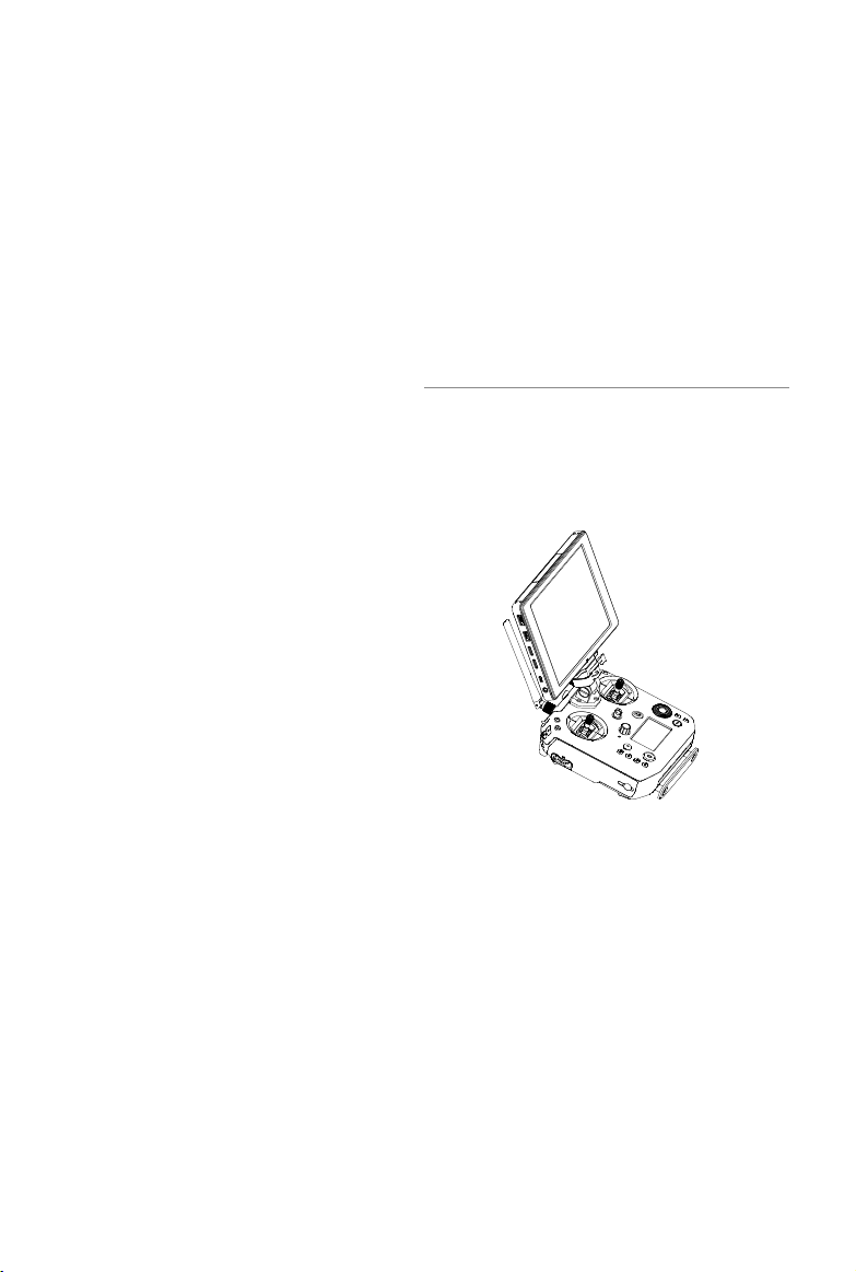
Mounting the Monitor to the Remote Controller
Mounting the DJI CrystalSky Monitor*
Ensure that Part B is
unlocked. Connect Part
B to Part A.
Lock the Mounting Bracket.
Use a coin or the
screwdriver included to
adjust the tightness of
the tilt axis.
Mounting the Other Mobile Devices
For other mobile devices (e.g. iPhones, iPads), the Cendence Mobile Device Holder and an
appropriate USB cable are required.
Mounting the Monitor to the Remote Controller
A
B
Lock the Mounting
Bracket.
Use a coin or the
screwdriver included
to adjust the tightness
of the tilt axis.
Ensure that Part B is
unlocked. Connect
Part B to Part A.
Connecting the Mobile Device
Press the button to
release the clamp.
Place your mobile
device and adjust
the clamp to secure.
Connect your mobile
device with a USB cable.
A
B
2
3
1
* Note that the CrystalSky is excluded in the M200 V2.
©
2019 DJI All Rights Reserved.
41
MATRICE 200
SERIES V2 User Manual
Remote Controller Operations
Button Types
Users can use the precongured buttons to control the aircraft and the camera and can also assign
functions to the customizable buttons through the DJI Pilot app. There are three types of button:
1. Precongured buttons for aircraft control, e.g. the Pause Button, RTH Button, etc.
2. Preconfigured buttons for camera control, e.g. the Shutter Button, Recording Button, Focus
Adjustment Knob, etc.
3. Customizable buttons and knobs that you can set through the DJI Pilot app.
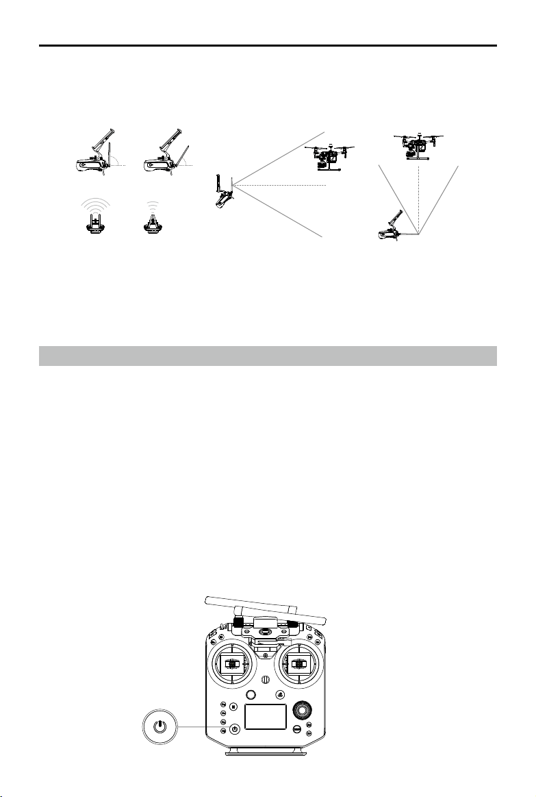
Turning the Remote Controller On and Off
Follow the steps below to turn the remote controller on and off.
1. Press the power button once to check the current battery level. Charge the remote controller if
the battery is too low.
2. Next, press and hold the Power button to power on the remote controller.
3. Repeat step 2 to power off the remote controller after you nish using it.
Optimal Transmission Range
The transmission signal between the aircraft and the remote controller is most reliable when the
antennas are positioned in relation to the aircraft as depicted below:
Optimal Transmission RangeOptimal Transmission Range
5.8 GHz
90° 60°
2.4 GHz
Strong Weak
Ensure the aircraft is ying within the optimal transmission zone. To maintain optimal transmission
performance, adjust the remote controller and antennas according to the above diagram. The posi-
tion of the antennas required for optimal transmission range varies in the frequency of 5.8 GHz and
2.4 GHz. Please place the antennas based on the actual operating frequency.
42
©
2019 DJI All Rights Reserved.
MATRICE 200
SERIES V2 User Manual
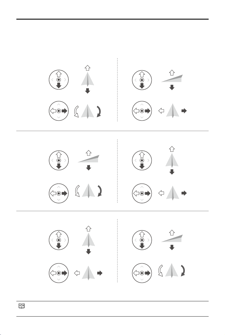
The Stick Mode is set to Mode 2 by default.
Stick Neutral/Mid-Point: Control sticks are centered.
Moving the Control Stick: Control sticks are pushed away from the center.
Right StickLeft Stick
Turn RightTurn Left
UP
Down
RightLeft
UP
Down
Turn RightTurn Left
RightLeft
Forward
Backward
Left Stick Right Stick
Forward
Backward
Right Stick
UP
Down
Forward
Backward
Left Stick
Turn RightTurn Left
RightLeft
Operating the Aircraft
Controlling the Aircraft
This section explains how to control the orientation of the aircraft through the remote controller.
Control can be set to Mode 1, Mode 2 or Mode 3, or to a custom mode.
Mode 1
Mode 2
Mode 3
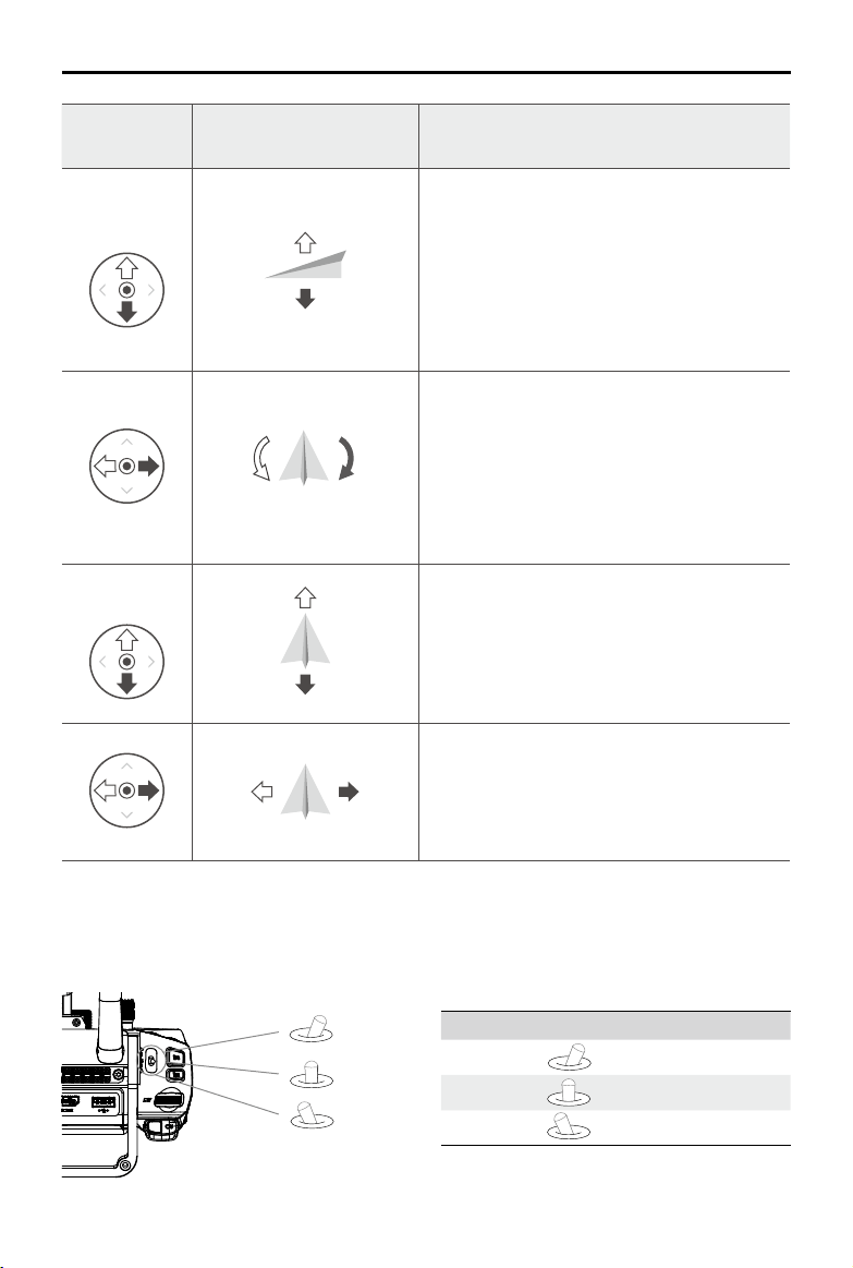
©
2019 DJI All Rights Reserved.
43
MATRICE 200
SERIES V2 User Manual
Remote
Controller
(Mode 2)
Aircraft Remarks
Left Stick
UP
Down
Moving the left stick up and down changes the
aircraft’s elevation.
Push the stick up to ascend and down to descend.
When both sticks are centered, the aircraft will
hover in place.
The more the stick is pushed away from the center
position, the faster the aircraft will change elevation.
Always push the stick gently to prevent sudden
and unexpected elevation changes.
Turn RightTurn Left
Moving the left stick to the left or right controls the
rudder and rotation of the aircraft.
Push the sick left to rotate the aircraft counter
clockwise, and push the stick right to rotate the
aircraft clockwise. If the stick is centered, the
aircraft will maintain its current orientation.
The more the stick is pushed away from the center
position, the faster the aircraft will rotate.
Right Stick
Forward
Backward
Moving the right stick up and down changes the
aircraft’s forward and backward pitch.
Push the stick up to y forward and down to y
backward. The aircraft will hover in place if the stick is
centered.
Push the stick further away from the center position for a
larger pitch angle and faster ight.
RightLeft
Moving the right stick control left and right changes the
aircraft’s left and right pitch.
Push left to y left and right to y right. The aircraft will
hover in place if the stick is centered.
Push the stick further away from the center position for
a larger pitch angle and faster ight.
Flight Mode Switch
Toggle the switch to select the desired ight mode. Choose between; P-mode, S-mode, and A-
mode.
Position Figure Flight Mode
Position 1
P-mode
Position 2
S-mode
Position 3
A-mode
Position 2
Position 3
Position 1
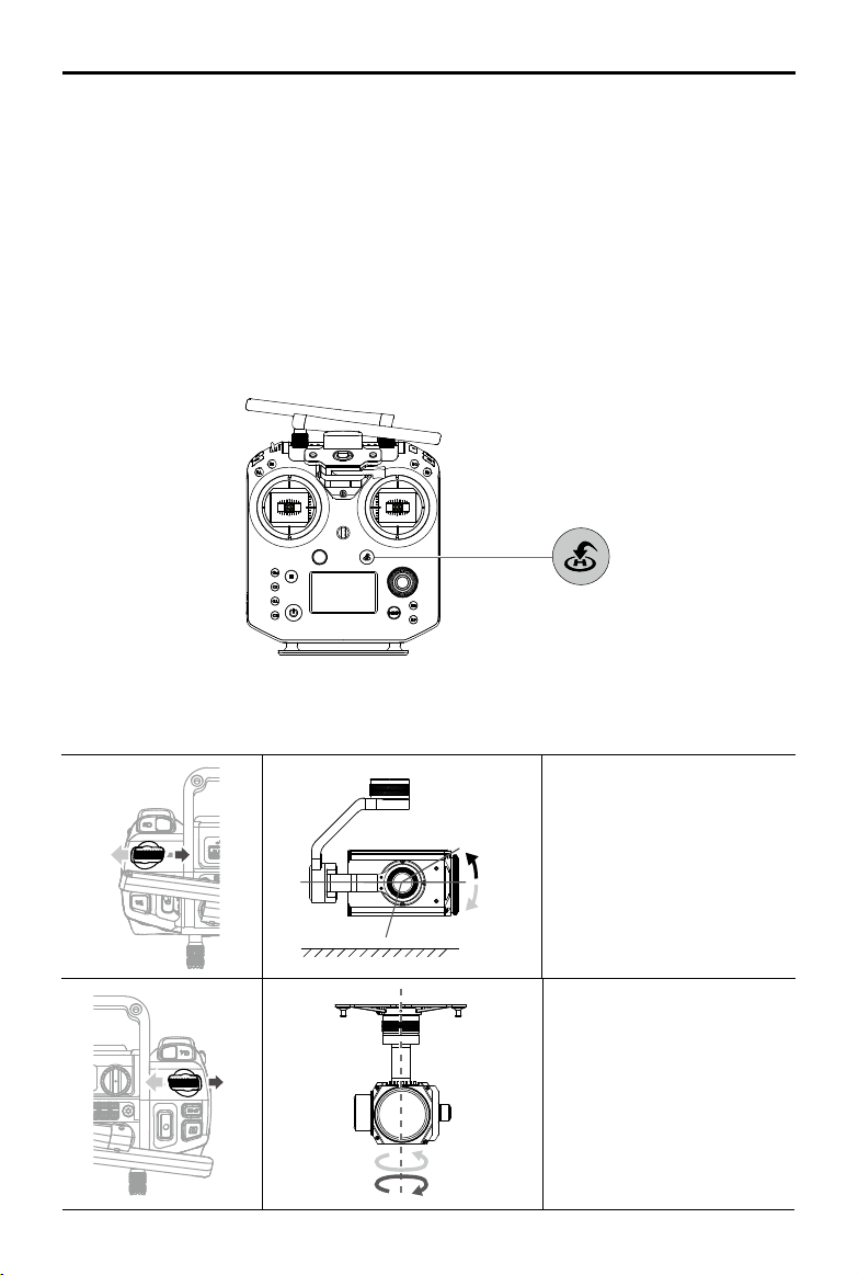
44
©
2019 DJI All Rights Reserved.
MATRICE 200
SERIES V2 User Manual
The Flight Mode Switch is locked to P-mode, regardless of the Flight Mode Switch's position. To
change ight modes, go to the Camera View in DJI Pilot and enable Multiple Flight Modes in Main
Controller Settings. After enabling multiple ight modes, toggle the switch to P for Position mode
and S for Sport Mode.
RTH Button
Press and hold the RTH button to start the Return to Home (RTH) procedure. The aircraft will then
return to the last recorded Home Point. Press this button again to cancel the RTH procedure and
regain control of the aircraft.
Determine RTH status by sound:
Single beep... Request to return, but not receive the respond from the aircraft yet.
Double beep... RTH in progress.
Controlling the Gimbal
Use the left dial and right dial to adjust the gimbal tilt.
The left dial controls the gimbal
tilt. Turn the dial to the right,
and the gimbal will shift to point
upwards. Turn the dial to the
left, and the gimbal will shift to
point downwards. The camera
will remain in its current position
when the dial is static.
horizon
+
30°
-120°
0°
+
320°
-320°
The right dial controls the
gimbal pan. Turn the dial to the
right, and the gimbal will shift
clockwise. Turn the dial to the
left, and the gimbal will shift
counter clockwise. The camera
will remain in its current position
when the dial is static.
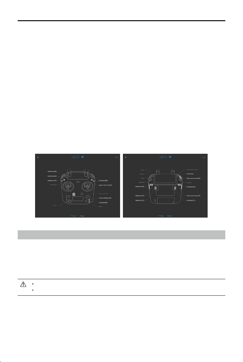
©
2019 DJI All Rights Reserved.
45
MATRICE 200
SERIES V2 User Manual
Operating the Camera
Shoot videos/photos with the Shutter Button and Video Recording Button on the remote controller.
1. Shutter Button
Press to take a photo. Photos can be taken even while recording video.
2. Video Recoding Button
Press once to start recording video, then press again to stop recording.
3. Autofocus button
Press once to focus automatically.
4. Focus Adjustment
Rotate Focus Adjustment Knob to set the focal length.
Controlling the FPV Camera
Press and hold C2 and turn the left dial to control the pitch of the FPV camera.
Conguring the Customizable Buttons
Go to the Customizable Button Settings Menu in DJI Pilot. Here you can set functions for the left C1-
C4 buttons, and BA-BH buttons.
Dual Remote Controller Mode
Introduction
Two remote controllers can connect to the same aircraft using Dual Remote Controller mode. The
master remote controller operator can control the orientation of the aircraft, gimbal movements and
camera operations, while the assistant remote controller can control the movement of the gimbal
and camera operations.
Only one remote controller can control the gimbal at a time.
When using the D-RTK 2 Mobile Station, Dual remote controller mode is not supported.
Setting up Dual Remote Controller Mode
Before using the Dual Remote Controller Mode, please congure the master and assistant remote
controllers separately by following the instructions below:
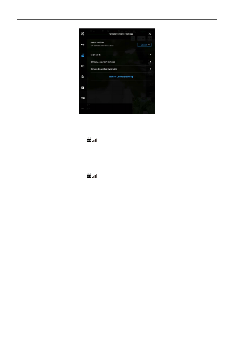
46
©
2019 DJI All Rights Reserved.
MATRICE 200
SERIES V2 User Manual
Master remote controller
1. Connect the remote controller to your mobile device and launch the DJI Pilot App.
2. Go to the Camera View and tap
to enter the remote controller settings window.
3. Select Master and set the remote controller as the Master Remote Controller. Follow the prompts
to link the remote controller and aircraft. Once successfully linked, conguration is complete.
Assistant remote controller
1. Connect the remote controller to your mobile device and launch DJI Pilot App.
2. Go to the Camera View and tap
to enter the remote controller settings window.
3. Set the remote controller as the Assistant Remote Controller. Follow the prompts to link the remote
controller and aircraft. Once successfully linked, conguration is complete.
When using the Dual Remote Controller Mode, the gimbal mode of the Assistant remote controller
can be set in the app (Pilot app v1.5.0 or latest is required). The four modes are:
Mode 1: Left stick controls the gimbal pitch, right stick controls the gimbal yaw.
Mode 2: Left stick controls the gimbal yaw, right stick controls the gimbal pitch.
Mode 3: Left stick controls the gimbal pitch and yaw, right stick controls none.
Mode 4: Left stick controls none, right stick controls the gimbal pitch and yaw.
Distinctions between Master and Assistant Remote Controllers
1. Control
The Assistant Remote Controller controls the movement of the gimbal and camera operations.
When the Master Remote Controller is controlling the gimbal, the Assistant Remote Controller can
only perform camera operations.
2. Remote controller display screen and buttons
The Flight Mode Switch and Return-to-Home button are disabled on the Assistant Remote
Controller. The Master Remote Controller display screen shows the ight parameters and the
assistant remote controller display screen shows the camera parameters.
3. App parameter settings
On the Assistant Remote Controller, the Flight Control Parameter Settings, Sensing Settings, RTK
Settings, and part of Video Transmission Settings are disabled in the DJI Pilot App, while the
Intelligent Battery Settings, Gimbal Settings, and part of Video Transmission Settings are enable.
Other settings for the Master and Assistant Remote Controllers are the same in the DJI Pilot App.
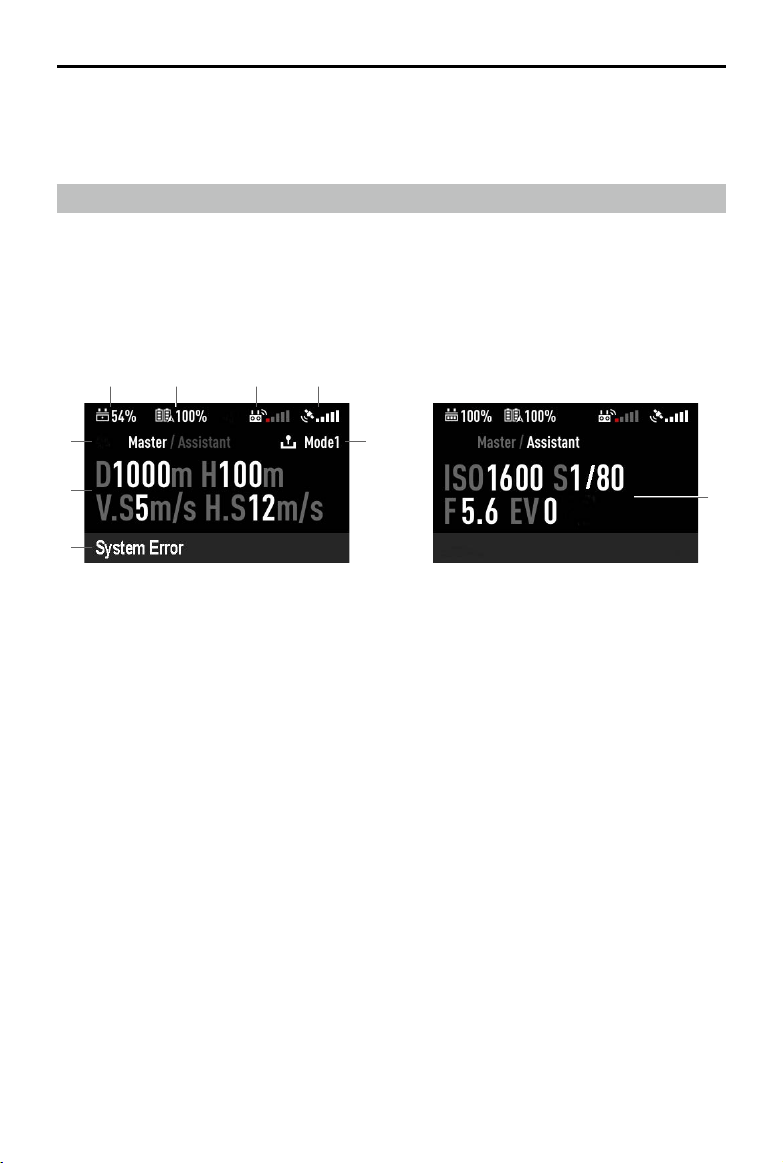
©
2019 DJI All Rights Reserved.
47
MATRICE 200
SERIES V2 User Manual
Master Remote Controller Assistant Remote Controller
1 2
5
7
8
9
6
3 4
1. Remote Controller Battery Level
Shows the current remote controller battery level.
2. Intelligent Flight Battery Level
Shows the current intelligent ight battery level.
3. Remote Controller Signal
This icon shows the strength of the remote controller signal.
4. GPS Signal Strength
Shows the current GPS signal strength.
5. Master and Assistant Remote Controller Display
"Master" shows Master Remote Controller while “Assistant” shows Assistant Remote Controller.
6. Remote Controller Operation Mode
The Master remote controller shows the current remote controller operation mode, including
Mode 1, Mode 2 and Mode 3. The Assistant remote controller does not show this item.
7. Fight OSD
Master remote controller shows the ight OSD, including horizontal distance, height, horizontal
speed and vertical speed.
8. Remote Controller Status
Master remote controller shows the remote controller status, including System Error, Low Battery,
and Fan Stuck.
9. Camera Parameters
Assistant remote controller shows the camera parameters, including ISO, S, F, and EV values.
4. App Functions
On the Assistant Remote Controller, the Flight Route function and Playback function are
unavailable in DJI Pilot.
Remote Controller Screen Descriptions
The remote controller of the M200 Series V2 has a screen that is primarily used to display aircraft
and camera parameters.
Dual Remote Controller Mode
When using in dual remote controller mode, the contents of the Master and Assistant remote
controller displays are different.
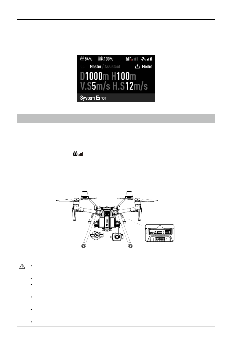
48
©
2019 DJI All Rights Reserved.
MATRICE 200
SERIES V2 User Manual
Linking the Remote Controller
The remote controller comes linked to your aircraft before delivery. Linking is only required when
using for the remote controller for the rst time. Follow these steps to link a remote controller:
1. Power on the remote controller, connect to your mobile device, and launch DJI Pilot.
2. Power on the Intelligent Flight Battery.
3. Enter the Camera View >
, and tap the Linking Remote Controller button.
4. The DJI Pilot app will display a countdown box, the remote controller will be ready to link, with its
display showing Connecting and a beeping sound being emitted.
5. Locate the Linking button on the aircraft and press the Linking button to start linking. The remote
controller display shows the current status information.
Restart the remote controller and try again if the remote controller display shows No
Connection indicating that linking failed.
Fully charge the remote controller before each ight.
If the remote controller is powered on and is NOT in use for five minutes, an alert will
sound. After 6 minutes, it will automatically power off. Move the sticks to cancel the alert.
Ensure the antennas of the remote controller are unfolded and adjusted to the proper
position to achieve optimal transmission quality.
Repair or replace the remote controller if damaged. A damaged remote controller antenna
greatly decreases performance.
Fully charge the battery at least once every three months to maintain battery health.
Single Remote Controller Mode
When using single remote controller, the screen display is the same as that of the Master display of
the dual remote controller mode.
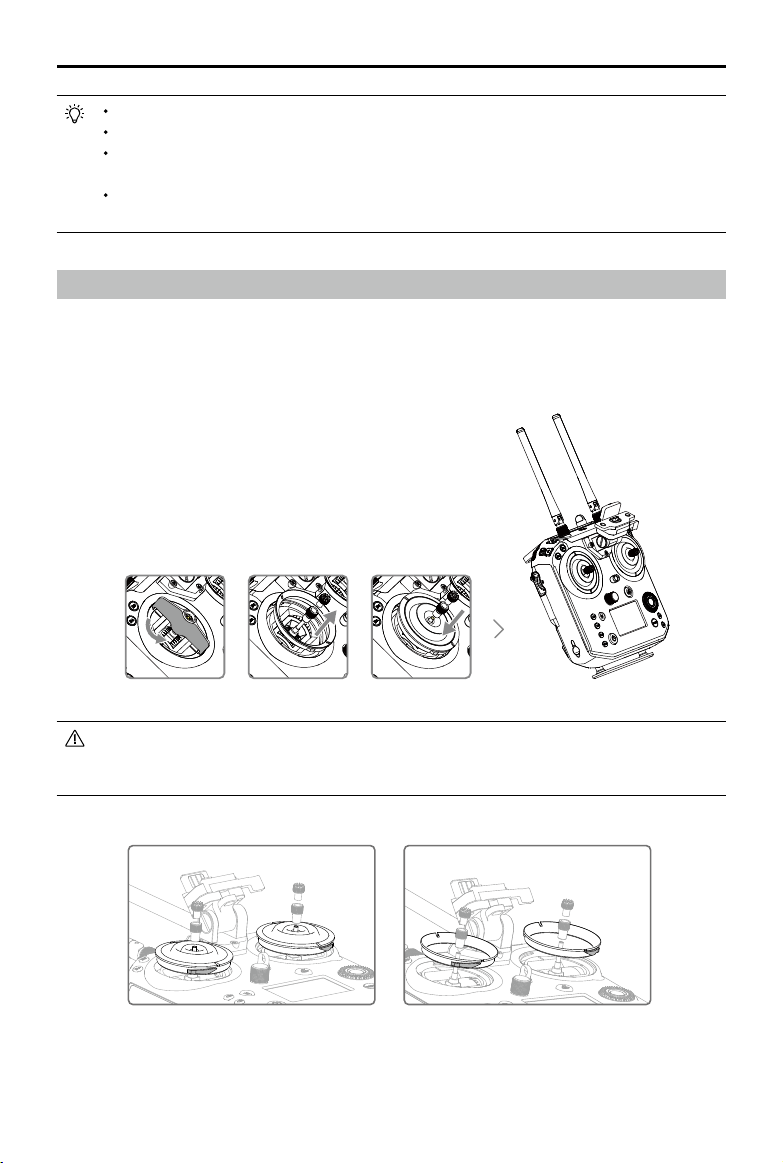
©
2019 DJI All Rights Reserved.
49
MATRICE 200
SERIES V2 User Manual
Mounting the Control Stick Covers
1. Remove the rings around the sticks with the Control Stick Cover Mounting Key, and the screws on
the top of the sticks.
2. Mount the Control Stick Covers to the remote controller and secure them with the Control Stick
Cover Mounting Key.
3. Reattach the screws to the sticks.
The two Control Stick Covers are not the same, and neither are the two rings around the
sticks. The left and right Control Stick Covers and rings can be distinguished using the
gures below. Be sure to install each Control Stick Cover on the correct side.
Press the C1 and C2 buttons and the Start/Stop button for fast linking.
Ensure the r emote controller is within 1.6 ft (0.5 m) of the air craft during linking.
The remote controller will unlink itself from an aircraft if a new remote controller links to the
same aircraft.
In Dual Remote Controller Mode, the Assistant remote controller must also be relinked to
the aircraft when the Primary remote controller is relinked to the aircraft.
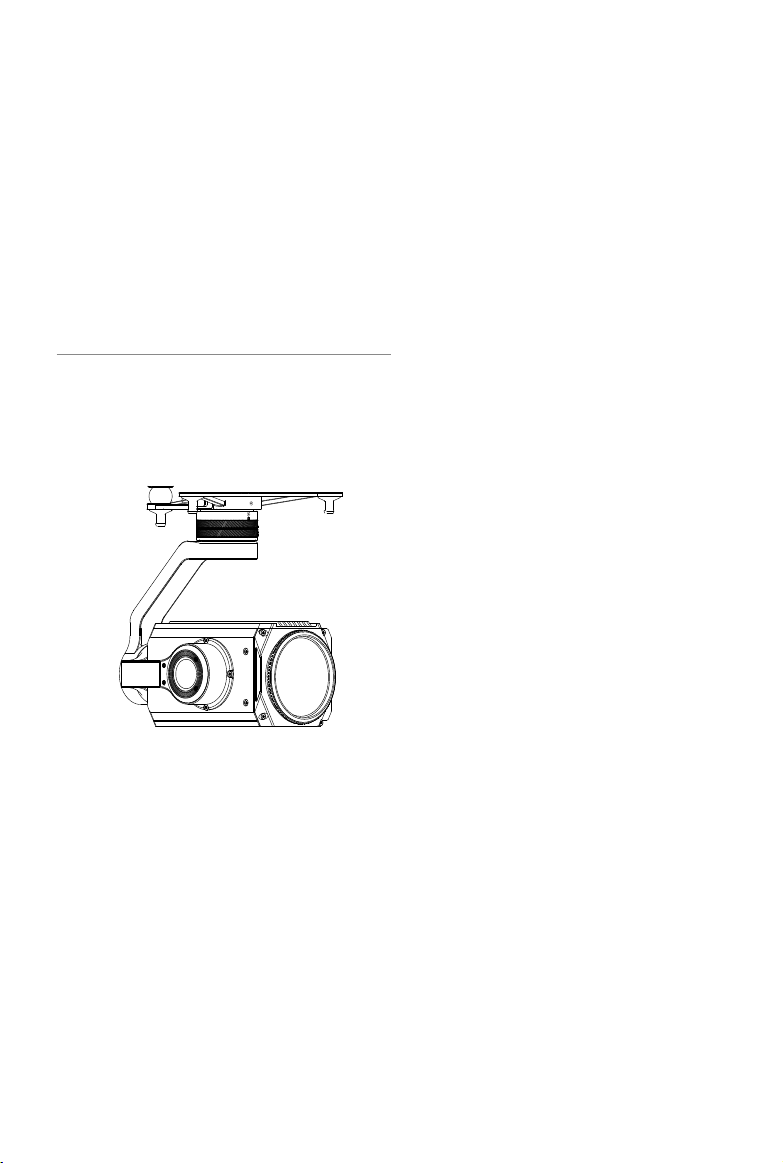
Gimbal and Camera
This section focuses on the technical
specications of the camera and explains
how to use the gimbal.
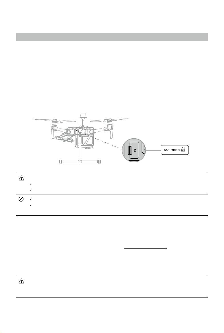
©
2019 DJI All Rights Reserved.
51
Gimbal and Camera
Camera
Camera Prole
Using the Zenmuse Z30 / X5S as an example, this section will demonstrate the technical
specications of the camera while explaining how to use the gimbal.
Camera microSD Card Slot
When using a Zenmuse X4S, X5S or X7, to store photos and videos, plug the microSD card into the
slot shown below before powering on the aircraft. The aircraft comes with a 64 GB microSD card
which was inserted into the slot before delivery and can support card sizes of up to 128 GB. We
recommend you use a UHS-I type microSD card with a write speed at least 20 MB/s because the
fast read and write capability of these cards enables you to store high-resolution video data.
The M210 V2 / M210 RTK V2 currently supports the following microSD.
Lexar 633X UHS-I microSDXC 64GB (model: LSDMI64GBBAP633A)
Samsung PRO Endurance UHS-I microSDXC 64GB (model: MB-MJ64G)
Do not remove microSD card from the aircraft when it is powered on.
To ensure the stability of the camera system, single video recordings are capped at 30
minutes.
Camera Operation
Remote Controller
Use the Shutter and Record buttons on the remote controller to shoot photos or videos. For more
information on how to use these buttons, please refer to Operating the Camera.
DJI Pilot
Use DJI Pilot to shoot photos or videos. For more information, refer to the camera and gimbal User
Manual.
When using the M200 Series V2 with the X5S or X7, some functions and parameters are
unavailable, such as functions requiring an SSD, color settings of D-Cinelike, D-Log and
Film Locks for the X5S, photo size of 3:2 for the X7.
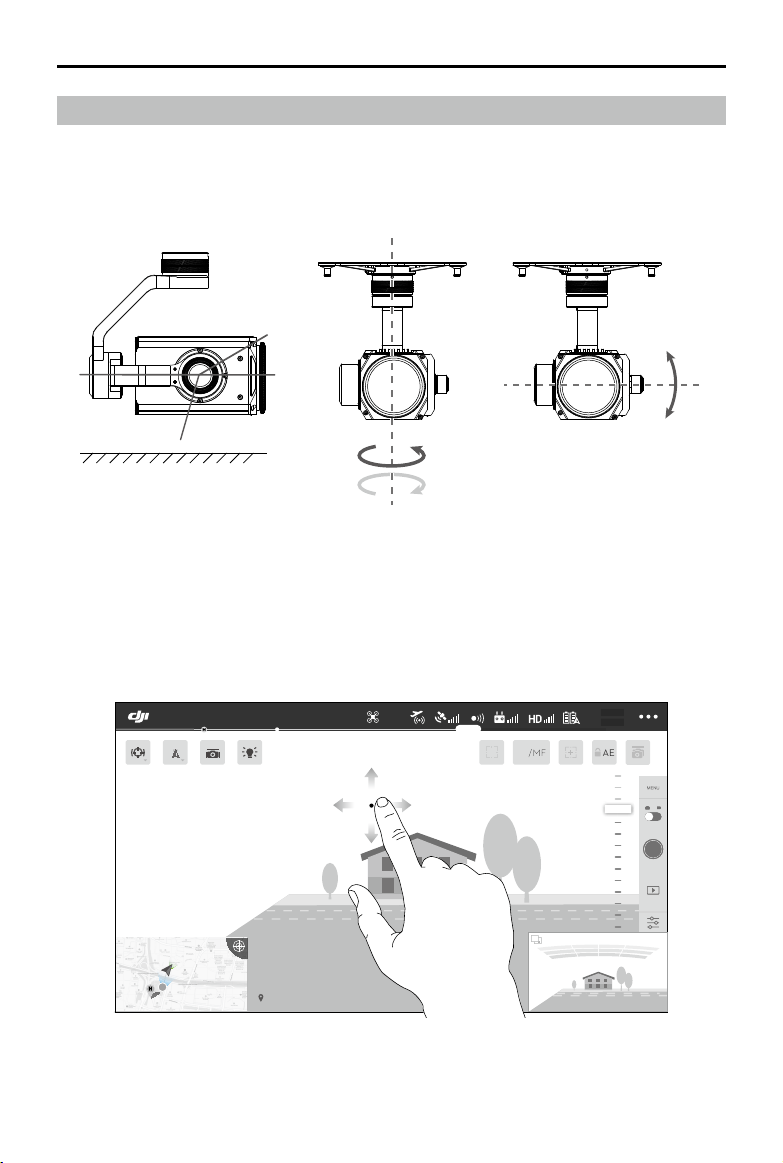
52
©
2019 DJI All Rights Reserved.
MATRICE 200
SERIES V2 User Manual
Using the DJI Pilot App to Control Gimbal
Follow the steps below to use the DJI Pilot app to control gimbal orientation:
1. Launch DJI Pilot and enter the Camera View.
2. Tap and press on the screen until a blue circle is shown.
3. Slide to control the gimbal's orientation within the Camera View as shown below.
Gimbal
Gimbal Prole
The 3-axis gimbal provides a steady platform for the attached camera, allowing you to capture
stabilized images and video Users can control gimbal angles using the remote controller or the app.
502 m
D 30 m
D
120 m
H 10 m
H
16.0 m/s
H.S 10.0 m/s
H.S
24.0 m/s
V.S 2.0 m/s
V.S
123456
2: 12: 45
123456
113.95357, 22.54268
19:29
AF
/MF
74%
74%
4.07V
4.07V
AE
P-GPS
In Flight (GPS)
+
320°
+
20°
-320° -20°
+
30°
-120°
0°
horizon
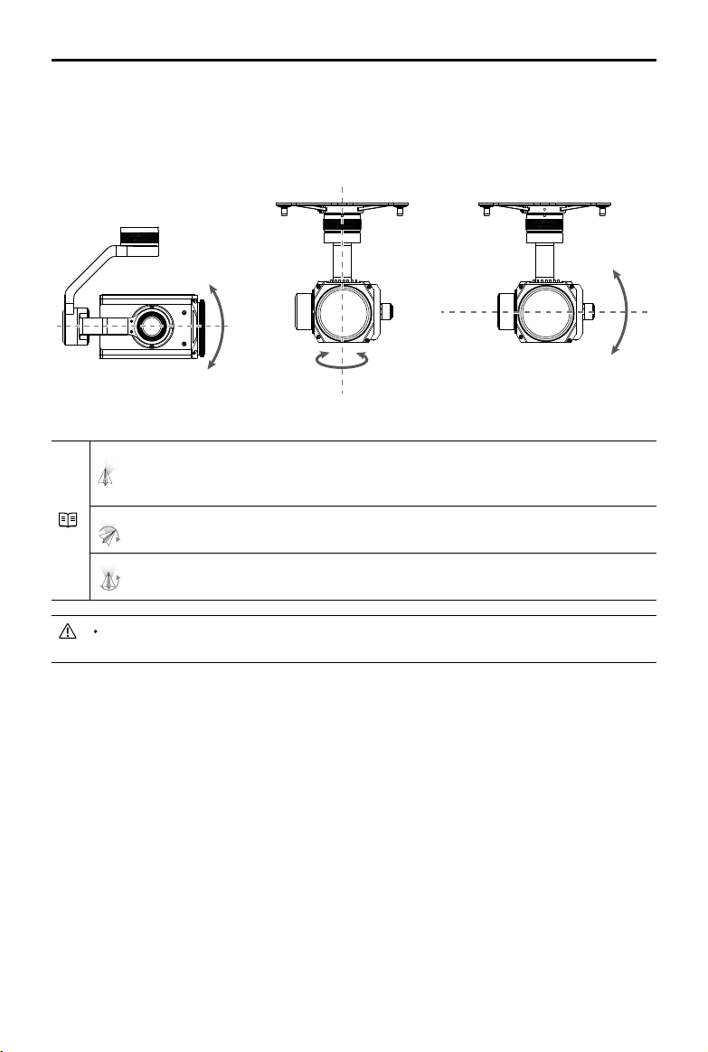
©
2019 DJI All Rights Reserved.
53
MATRICE 200
SERIES V2 User Manual
Pitch Pan
Gimbal Operation Modes
Three gimbal operation modes are available. Switch between the different operation modes in DJI
Pilot's Camera View. Note that your mobile device must be connected to the remote controller for
changes to take effect. Refer to the table below for details:
Roll
Follow Mode
When the aircraft turns horizontally, the gimbal will pan with the
aircraft so that the relative angle of the gimbal and the aircraft’s
heading remains the same.
Free Mode
The gimbal pan will remain unchanged when the aircraft’s orientation
changes.
Reset
The gimbal will pan to realign with the aircraft's nose. The gimbal
pitch will realign to the central position.
DO NOT block the gimbal. Place the aircraft on a at, open area before taking off. Do not
touch the gimbal after powered on.

DJI Pilot App
This section introduces the main
functions of the DJI Pilot app.
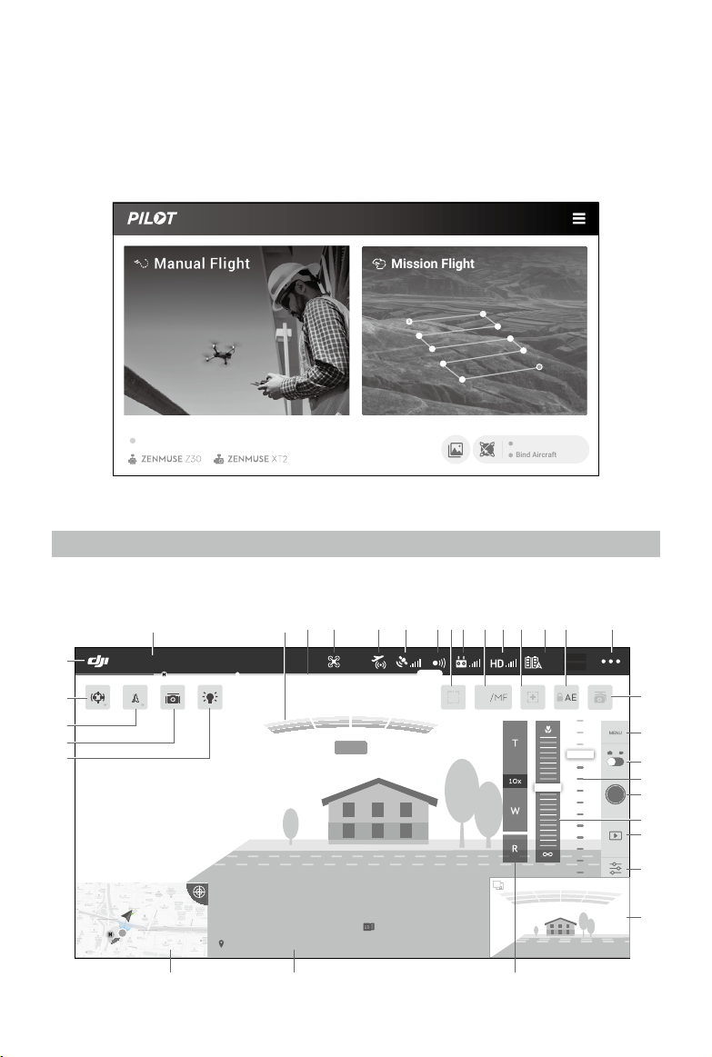
©
2019 DJI All Rights Reserved.
55
DJI Pilot App
The DJI Pilot app is specically developed for enterprise users. Manual ight integrates a variety of
professional features that make ying simple and intuitive. Mission ight supports ight planning,
and allows you to control the drone automatically, making your workow much simpler and more
efcient.
Manual Flight
Enter the Camera View by tapping Manual Flight. The descriptions below use a Z30 gimbal camera
as an example.
Bind Aircraft
S
Mission Flight
FlightHub Data Sync
M210 RTK V2
1.5M
502 m
D 30 m
D
120 m
H 10 m
H
16.0 m/s
H.S 10.0 m/s
H.S
24.0 m/s
V.S 2.0 m/s
V.S
123456
2: 12: 45
123456
113.95357, 22.54268
19:29
AF
/MF
74%
74%
4.07V
4.07V
AE
P-GPS
2.4G
In Flight (GPS)
1
27 26 25
2
3
4 5 6 7 98 1110 13 15
16
32
31
30
29
28
17
18
19
20
21
22
23
24
1412

56
©
2019 DJI All Rights Reserved.
MATRICE 200
SERIES V2 User Manual
1. System Status Bar
READY TO GO (GPS)
: This icon indicates aircraft ight status and displays various warning messages.
2. Obstacle Detection Status
: Red bars are displayed when obstacles are close to the aircraft. Orange or
yellow bars are displayed when obstacles are within the detection range.
3. Battery Level Indicator Bar
: The battery level indicator provides a dynamic display of the battery level. The
colored zones on the battery level indicator represent the power levels needed to carry out
different functions.
4. Flight Mode
: The text next to this icon indicates the current ight mode.
Tap to congure the Flight Controller settings. These settings allow you to modify ight limits
and set gain values.
5. AirSense Status
: AirSense Status displays information about nearby manned aircraft to ensure ight safety,
including the distance between DJI aircraft and manned aircraft. AirSense will instruct users to
land if nearby aircraft are detected.
6. GPS Signal Strength
: Shows the current GPS signal strength. For the M210 RTK V2, “R” will be displayed on
the lower right corner if the aircraft RTK is enabled. For the M210 V2, “
” will be displayed
if the external GPS module is used together. (App version must be v1.5.0 or later)
7. Obstacle Sensing Function Status
: Tap this icon to enable or disable features provided by the Vision System, and it displays
the status for all vision systems.
8. Focus/Metering Button
/
: Tap to switch between the focus and metering modes. Tap to select an object for
focusing or metering. Auto Focus-Continuous will be triggered automatically according to the
status of the aircraft and camera after enabling Auto Focus.
9. Remote Controller Signal
: This icon shows the strength of the remote controller signal. The icon will blink when an
interference is recognized during ight. When there are no additional warnings in DJI Pilot, it
means that the interference will not affect operation and overall ight experience.
10. AF/MF
: Tap to switch the focus mode.
11. HD Video Link Signal Strength
2.4G
: This icon shows the strength of the HD video downlink connection between the aircraft
and the remote controller. The text on top indicates the frequency in use. Tap for image
transmission settings.
12. Zoom
: Tap to enter zoom mode. Tap the screen to zoom into the pre-set TapZoom value
automatically. Manual zoom can be done by tapping the icon to pull out the zoom menu.
13. Battery Settings
: Shows the current battery level. Tap to view the battery information menu, set the
various battery warning thresholds, and view the battery warning history.

©
2019 DJI All Rights Reserved.
57
MATRICE 200
SERIES V2 User Manual
14. Auto Exposure Lock
AE
: Tap to lock the exposure value. AE
15. More Settings
Tap
to enter the extended menu to view and adjust the parameters of all other settings.
: Flight Controller Settings — Includes Home Point settings, Return to Home altitude,
maximum altitude, distance limit, sensors state, remote controller signal lost action, remote
controller signal lost action, center of gravity auto calibration, extended IO options, etc.
: Perception Settings — Includes enabling obstacle sensing, vision positioning, and RTH
obstacle detection, etc.
: Remote Controller Settings — Includes stick mode, Cendence custom settings, remote
controller calibration, linking, etc.
: Image Transmission Settings — Includes camera for image transmission (to set the source
for the main and assistant camera preview), work frequency, channel mode and video output,
etc.
: Aircraft Battery Settings — Includes low battery warning thresholds, battery information,
etc.
: Gimbal Settings — Includes gimbal pitch and pan settings, TapZoom magnication (for
the Z30 gimbal and camera), gimbal calibration, etc.
RTK: RTK Settings — Includes RTK function switch, RTK service type and their corresponding
settings.
: Common Settings — Includes ight route display, units of measurement, live stream, etc.
16. Dual Gimbal Control (Supported with M210 V2 / M210 RTK)
: Tap to enable dual gimbal control function to control the pitch and pan of two gimbals
simultaneously.
17. Camera Settings
Tap to enter the photo and video settings. Tap
to congure photo settings such as photo
mode and image format. Tap
to congure video settings such as video size and format.
Tap
to congure video caption, grid and smart LED settings (to enable/disable arm LEDs,
beacon LEDs and status LEDs). The settings may vary according to different camera models.
18. Photo / Video Toggle
: Tap to switch between photo and video recording modes.
19. Gimbal Slider
: Displays the gimbal tilt angle.
20. Shutter / Record Button
/
: Tap to shoot photos or start/stop recording. Users can also press the Shutter or Record
button on the remote controller to shoot photos or record video.
21. Manual Focus
Only available in MF mode. Focus can be adjusted manually.
22. Playback
: Tap to enter Playback and preview photos and videos as soon as they are captured.
23. Parameter Settings
: Tap to set ISO, shutter, exposure values and other parameters.
24. FPV Camera / Gimbal Camera Preview
FPV camera preview will be displayed if using a single gimbal. Preview of the other gimbal
and camera will be displayed if using dual gimbal. Users can also select the display source in
Image Transmission Settings page.
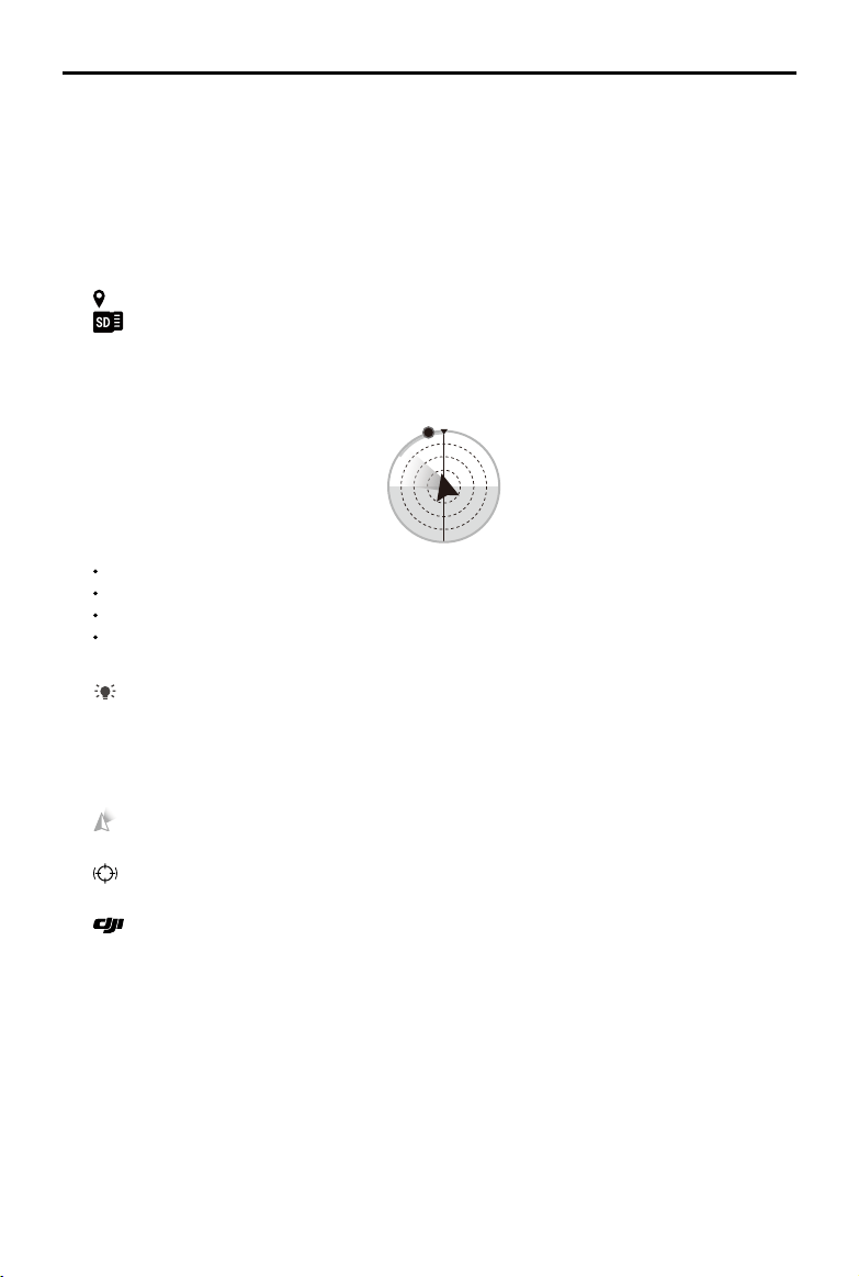
58
©
2019 DJI All Rights Reserved.
MATRICE 200
SERIES V2 User Manual
25. Zoom Menu
Tap and hold T to zoom in. The magnication will be displayed under the button. Tap and hold
W to zoom out. Tap R to reset the magnication to 1x.
26. Flight Telemetry
D 30 m
: Horizontal distance between the aircraft and the Home Point.
H
10.0 m
: Height from the Home Point.
HS
10.0 m/s
: Aircraft horizontal speed.
VS
2.0 m/s
: Aircraft vertical speed.
113.95434, 22.54764
: The longitude and latitude of the aircraft.
2:12:45
: Shows the remaining capacity or recording duration.
27. Map
Tap to view the map. Tap the icon on the upper right corner to show the ight attitude and radar
display.
N
The red arrow shows which direction the aircraft is facing.
The ratio of gray area to blue area indicates the aircraft’s pitch.
The horizontal level of the gray area indicates the aircraft’s roll angle.
A green arc indicates the gimbal's pan angel.
28. Beacon
: Tap to turn on/off the beacons.
29. Gimbal Stabilization
This icon will be displayed only if using a Z30 gimbal camera. Tap to enable gimbal stabilization
to reduce image shake during zoom.
30. Gimbal Operation Mode
: Tap to switch between Follow mode and Free mode, or to reset the gimbal.
31. Spotlight Pro
: Tap to enable or disable Spotlight Pro. Heat Track is available when using an XT2 camera.
32. Back
: Tap this icon to return to the main menu.
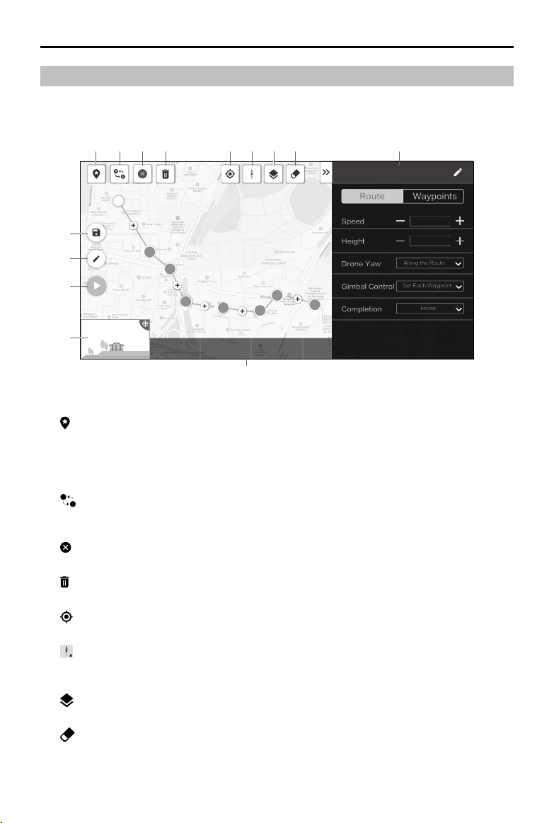
©
2019 DJI All Rights Reserved.
59
MATRICE 200
SERIES V2 User Manual
Mission Flight
Tap to enter the mission library. Set a waypoint ight path including up to 240 waypoints, dene
waypoint actions then start ying with a tap.
19:29
In Flight (GPS)
74%
70%
4.07V
4.07V
1243 m
4 m 17 s
8
0
Task1
Waypoints
Speed
Height
Drone Yaw
Route
5m /s
10m
Along the Route
Gimbal Control
Set Each Waypoint
Completion
Hover
S
E
Estimated TimeDistance Waypoints Photos
S
2
3
4
5
7
6
8
1
10
12
11
13
14
2 3 4 5 6 7 8 9
Tap on the map to add waypoints, then congure route and waypoints settings.
1. Point of Interest (POI)
: Tap to enable the POI function and a POI will be displayed on the map. Drag to adjust its
position. When the POI function is enabled, the drone yaw can be set to center to POI so that
the aircraft nose points at the POI during the mission. Tap this icon again to disable the POI
function.
2. Reverse Path
S
E
: Tap it to swap the start and end points to reverse the ight path. “S” refers to the start
point.
3 Clear Waypoints
: Tap to clear all the added waypoints.
4. Delete Selected Waypoint
: Tap to delete the selected waypoint.
5. Location
: Tap to center the map around the aircraft’s location.
6. Map Lock
: Map rotation is locked by default. North is at the top. Tap the button to unlock rotation. Then
users can adjust the map orientation by tapping and rotating two ngers on the map.
7. Map Mode
: Tap to switch between Standard and Satellite mode.
8. Clear Screen
: Tap to clear the ight path currently shown on the map.
9. Parameter List
Edit the mission name and congure Route and Waypoints settings in the list.

60
©
2019 DJI All Rights Reserved.
MATRICE 200
SERIES V2 User Manual
Route
The settings are applied to the entire route, including aircraft speed, height, yaw, gimbal control,
and completion action.
Drone Yaw:
a. Along the route: The aircraft’s nose is always aligned to the direction of the next two
waypoints.
b. Manual: Users manually control the aircraft heading using the control sticks.
c. Set Each Waypoint: Set aircraft heading at each waypoint in “Waypoints” settings.
d. Center to POI: This option will be displayed when a POI is added. The aircraft’s now is
always pointing at the POI.
Gimbal Control:
a. Manual: Users manually control the gimbal angle through the gimbal dial.
b. Set Each Waypoint: Set gimbal pitch angle at each waypoint in “Waypoints” settings.
Waypoints
The settings are applied to the selected waypoint, including aircraft height, yaw, rotation, gimbal
pitch, and waypoint actions.
Select a waypoint and then set waypoint parameters. Tap “<” or “>” to switch to the previous or
next waypoint.
Height:
a. Follow Route: The aircraft height will be set according to “Route” settings.
b. Dened: Input a custom height value.
Drone Yaw, Aircraft Rotation: These two options will be available to set the aircraft heading at
the selected waypoint and the aircraft rotation direction when ying to the next waypoint if “Set
Each Waypoint” is set for “Drone Yaw” in “Route” settings.
Gimbal Pitch: This option will be available to set the gimbal pitch angle if “Set Each Waypoint”
is set for “Gimbal Control” in “Route” settings.
Actions:
Tap to enter the action list. Tap + to add the desired waypoint action and set its corresponding
parameters. Tap and hold the icon
on the left of the added action, drag it to re-order the
actions. To delete the action, swipe it to the left and choose an option.
10. Mission Information
Shows the ight length, estimated ight time, waypoint quantity, and photo quantity.
11. Camera Preview
The real-time camera view will be shown here once the aircraft is connected.
12. Perform
: Tap the button and then check the settings and status of the aircraft in the pop-up
checklist. Tap the “Start to Fly” button to perform the mission.
13. Edit
: If the path is not in edit mode, tap the icon to enter edit mode to edit the mission.
14. Save
: Tap to save current settings.
©
2019 DJI All Rights Reserved.
61
MATRICE 200
SERIES V2 User Manual
Album
View your masterpieces all in one place. You can save the photos or videos to the CrystalSky
monitor or your mobile device.
DJI FlightHub
Content related to DJI FLIGHTHUB
TM
will be shown here if the DJI account used has a FlightHub
license.
DJI FlightHub is a web-based drone management platform that provides users with real-time
monitoring, ight logs and data, team management and more.
For more information, please visit www.dji.com/ighthub
Menu
Tap on the upper right corner to enter the menu for ofine maps, ight records, GEO unlocking
and more settings.
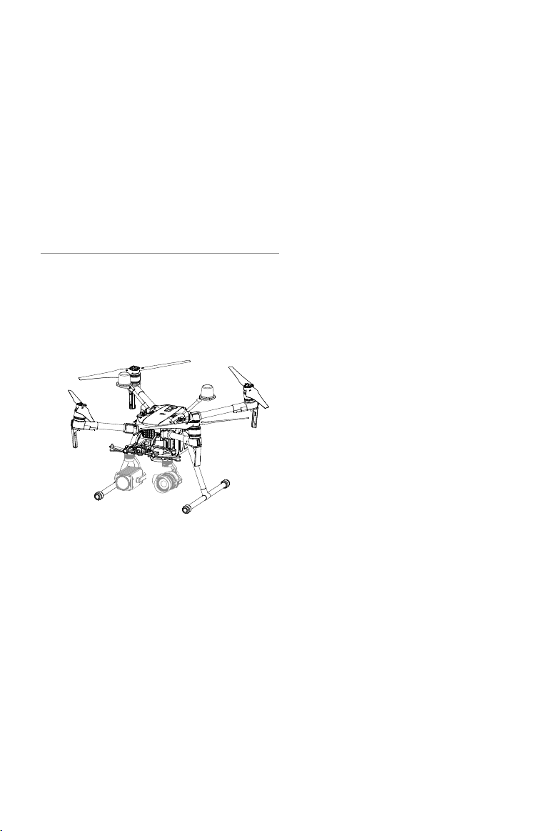
Flight
This section describes safe ight
practices and ight restrictions.

©
2019 DJI All Rights Reserved.
63
Flight
Once pre-flight preparation is complete, it is recommended to use the flight simulator in DJI
Assistant 2 for Matrice to hone your ight skills and practice ying safely. Ensure that all ights are
carried out in an open area. It is important to understand basic ight guidelines for the safety of
both you and those around you. Refer to the Disclaimer and Safety Guidelines for more information.
Flight Environment Requirements
1. Do not use the aircraft in severe weather conditions. These include wind speeds exceeding 12 m/s,
snow, rain, and fog.
2. When ying in open areas, tall and large metal structures may affect the accuracy of the onboard
compass and GPS system.
3. Avoid obstacles, crowds, high voltage power lines, trees, and bodies of water.
4. Minimize interference by avoiding areas with elevated levels of electromagnetism, including base
stations and radio transmission towers.
5. Aircraft and battery performance is subject to environmental factors such as air density and
temperature. Be very careful when ying at high altitudes, as battery and aircraft performance
may be affected.
6. The compass and GPS will not work in Polar Regions. The aircraft will have to auto switch to
A-mode, using the Vision System for positioning.
GEO (Geospatial Environment Online) System
Introduction
DJI’s Geospatial Environment Online (GEO) System is a global information system committed to
providing real-time airspace information within the scope of international laws and regulations.
GEO provides flight information, flight times and location information to assist Unmanned Aerial
Vehicle (UAV) users in making the best decisions related to their personal UAV use. It also includes
a unique Regional Flight Restrictions feature which provides real-time ight safety and restriction
updates and blocks UAVs from ying in restricted airspace. While safety and obeying air trafc
control laws is a paramount concern, DJI recognizes the need for exceptions to be made under
special circumstances. To meet this need, GEO also includes an Unlocking feature that enables
users to unlock flights within restricted areas. Prior to making their flight, users must submit an
unlock request based on the current level of restrictions in their area.
GEO Zones
DJI’s GEO System designates safe flight locations, provides risk levels and safety concerns for
individual ights, and offers restricted airspace information, which can be viewed by users in real
time on the DJI Pilot app. The locations designated by GEO are called GEO Zones. GEO Zones
are specic ight areas that are categorized by ight regulations and restrictions. GEO Zones that
prohibit ight are implemented around locations such as airports, power plants, and prisons. They
can also be temporarily implemented around major stadium events, forest res, or other emergency
situations. Certain GEO Zones do not prohibit flight but do trigger warnings informing users of
potential risks. All restricted ight areas are referred to as GEO Zones, and are further divided into
Warning Zones, Enhanced Warning Zones, Authorization Zones, Altitude Zones, and Restricted
Zones. By default, GEO limits flights into or taking off within zones that may result in safety or
security concerns. There is a GEO Zone Map, which contains comprehensive global GEO Zone
information on the ofcial DJI website: https://www.dji.com/ysafe/geo-map

64
©
2019 DJI All Rights Reserved.
MATRICE 200
SERIES V2 User Manual
The GEO System is for advisory purposes only. Individual users are responsible for checking ofcial
sources and determining which laws or regulations may apply to their ight. In some instances,
DJI has selected widely-recommended general parameters (such as a 1.5-mile radius at airports)
without making any determination as to whether these guidelines match regulations that apply to
specic users.
GEO Zone Denitions
Warning Zones: Users receive a warning message with information relevant to their ight.
Enhanced Warning Zones: Users receive a prompt from the GEO System at the time of ight. They
are required to submit an unlock request to y in the zone, for which they must conrm their ight
path.
Authorization Zones: Users receive a warning message and the flight is prohibited by default.
Authorization Zones can be unlocked by authorized users with a DJI-verified account. Self-
Unlocking privileges must be applied for online.
Altitude Zones: Flights are limited to a specic altitude.
Restricted Zones: Flights are completely prohibited. UAVs cannot y in these zones. If you have
obtained permission to y in a Restricted Zone, please go to https://www.dji.com/ysafe or contact
[email protected] to unlock the zone.
DJI GEO Zones aim to ensure the user’s flight safety, but it cannot be guaranteed to be in full
compliance with local laws and regulations. Users should check local laws, regulations, and
regulatory requirements before each ight and are responsible for the ight safety.
All intelligent ight features will be affected when DJI aircraft y nearby or into GEO Zones. Such
interference includes, but is not limited to, decreased speed, takeoff failure, and ight termination.
Flight Restrictions
Introduction
UAV operators should abide by all ight regulations established by the relevant government and
regulatory agencies, including the ICAO and the FAA. For safety reasons, ights are restricted by
default, which helps users operate DJI products safely and legally. Flight restrictions include altitude
and distance limits, and GEO Zones.
When Global Navigation Satellite Service (GNSS) is available, altitude limits, distance limits, and
GEO Zones are all taken into account to ensure ight safety. Otherwise, only altitude limits take
effect.
Maximum Altitude & Radius Restrictions
Maximum flight altitude restricts an aircraft’s flight altitude, while maximum radius restricts its
distance. These limits can be set using the DJI Pilot app.
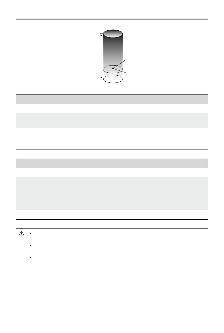
©
2019 DJI All Rights Reserved.
65
MATRICE 200
SERIES V2 User Manual
When an aircraft exceeds a specied limit, the pilot can still control the aircraft but it will
be unable to y any farther.
When an aircraft exceeds the max radius it automatically ies back within range when
GPS signal is strong.
For safety reasons, do not y near airports, highways, railway stations, railway lines, city
centers, or other sensitive areas. Only y aircraft in areas that are within your direct line of
sight.
Strong GPS Signal
Restriction Description DJI Pilot App Message
Max Altitude
Aircraft's altitude cannot exceed
the specied value.
Maximum Flight Altitude reached. Adjust
your altitude using FC Settings if required.
Max Radius
Flight distance cannot exceed
the specied value.
Maximum Flight Distance reached.
Adjust your distance using FC Settings if
required.
Weak GPS Signal
Restriction Description DJI Pilot App Message
Max Altitude
Altitude is restricted to 26 ft (8 m) when
GPS signal is weak and the Vision System
is activated. Altitude is restricted to 98 ft
(30 m) when GPS signal is weak and the
Vision System is deactivated.
Maximum Flight Altitude
reached. Adjust your altitude
using MC Settings if required.
Max Radius No limit. N/A
Maximum Flight Altitude
Max Radius
Home Point
Height of aircraft when turned on
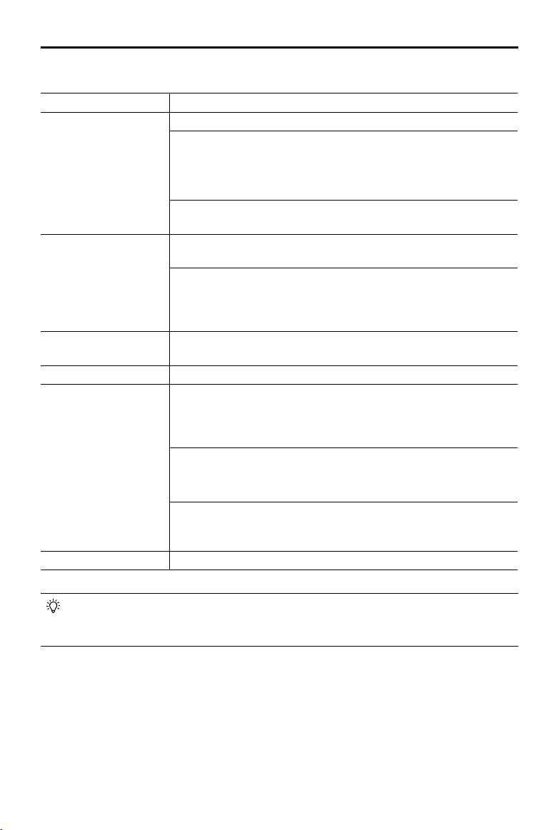
66
©
2019 DJI All Rights Reserved.
MATRICE 200
SERIES V2 User Manual
GEO Zone Description
Restricted Zone
Takeoff: The aircraft’s motors cannot be started.
In-ight: When GPS signal changes from weak to strong, DJI Pilot starts
a 20-second countdown. Once the countdown is over, the aircraft
immediately lands in semi-automatic descent mode and turns off its
motors after landing.
In-ight: When the aircraft approaches the boundary of the Restricted
Zone, it automatically decelerates and hovers.
Authorization Zone
Takeoff: The aircraft’s motors cannot be started. Takeoff is only available
after submitting an unlock request with the user’s phone number.
In-ight: When GPS signal changes from weak to strong, DJI Pilot starts
a 20-second countdown. Once the countdown is over, the aircraft
immediately lands in semi-automatic descent mode and turns off its
motors after landing.
Enhanced Warning Zone
The aircraft ies normally but the user is required to conrm the ight
path.
Warning Zone The aircraft ies normally but the user receives warning messages.
Altitude Zone
When GPS signal is strong, the aircraft cannot exceed the specied
altitude.
In-ight: When GPS signal changes from weak to strong, the aircraft will
descend and hover below the altitude limit.
When the GPS signal is strong, the aircraft approaches the boundary
of the Altitude Zone. If it is higher than the altitude limit, the aircraft
decelerates and hovers in place.
When the GPS signal changes from weak to strong, DJI Pilot app starts
a 20-second countdown. Once the countdown is over, the aircraft will
descend and hover below the altitude limit.
Free Zone The aircraft ies normally with no restrictions.
GEO Zone Flight Restrictions
Semi-Automatic Descent: All stick commands are available except the throttle command
and RTH button during descent and landing. The aircraft’s motors turn off automatically
after landing. It is recommended to y the aircraft to a safe location to land immediately.
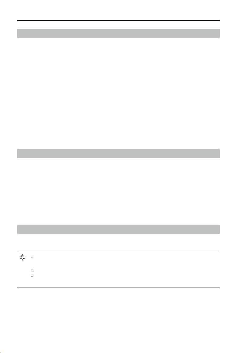
©
2019 DJI All Rights Reserved.
67
MATRICE 200
SERIES V2 User Manual
GEO Unlocking
Due to differing laws and regulations between countries and regions, and differing ight restrictions
between GEO Zones, DJI provides users with two methods for unlocking GEO Zones: Self-Unlocking
and Custom Unlocking.
Self-Unlocking is used for Authorization Zones, where the user is required to submit an unlock
request by authenticating their phone number for a registered DJI account. This feature is only
available in certain countries. Users can choose whether to submit their unlock request via the
website at https://www.dji.com/ysafe (Scheduled Self-Unlocking), or through the DJI Pilot app (Live
Self-Unlocking).
Custom Unlocking is based on special requirements for individual users. It sets a special ight
area that users can unlock by providing ight permission les according to their specic GEO
Zone and other requirements. It is available in all countries and can be applied for on the website:
https://www.dji.com/ysafe.
For more information about unlocking, please visit https://www.dji.com/ysafe or contact ysafe@
dji.com.
Preight Checklist
1. Remote controller, Intelligent Flight Battery, and display device are fully charged.
2. Frame arms and D-RTK antennas (for the M210 RTK V2) are unfolded and locked rmly, landing
gears are mounted rmly, and propellers and GPS kit (if in use) are mounted correctly.
3. All the devices' rmware is up-to-date.
4. microSD card has been inserted, if necessary.
5. Gimbal is functioning normally.
6. Motors can start and are functioning normally.
7. The DJI Pilot app is successfully connected to the aircraft.
8. Ensure that the sensors for the Vision and Infrared Sensing Systems are clean.
Calibrating the Compass
Only calibrate the compass when the DJI Pilot app or the status indicator prompts you to do so.
Observe the following rules when calibrating your compass:
DO NOT calibrate your compass where there is a chance of strong magnetic interference,
such as near magnets, parking structures, or steel reinforcements underground.
DO NOT carry ferromagnetic materials with you during calibration such as cellular phones.
The DJI Pilot app will notify you if the compass is affected by strong interference after
calibration is complete. Follow the prompts to resolve the compass issue.
Calibration Procedures
Choose an open area to carry out the following procedures.
1. Tap the Aircraft Status Bar in the app and select Calibrate, then follow the on-screen instructions.
2. Hold the aircraft horizontally and rotate it 360 degrees. The Aircraft Status Indicators will go solid
green.
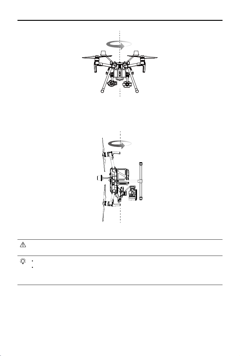
68
©
2019 DJI All Rights Reserved.
MATRICE 200
SERIES V2 User Manual
3. Hold the aircraft vertically, with the nose pointing downward, and rotate it 360 degrees around the
center axis. Re-calibrate the aircraft if the aircraft status indicators blink red.
If the Aircraft Status Indicator blinks red and yellow after the calibration procedure, move
your aircraft to a different location and try again.
DO NOT calibrate the compass near metal objects such as a metal bridge, cars, scaffolding.
If the aircraft status indicators are blinking red and yellow alternately after placing the aircraft
on the ground, the compass has detected magnetic interference. Please change your
location.
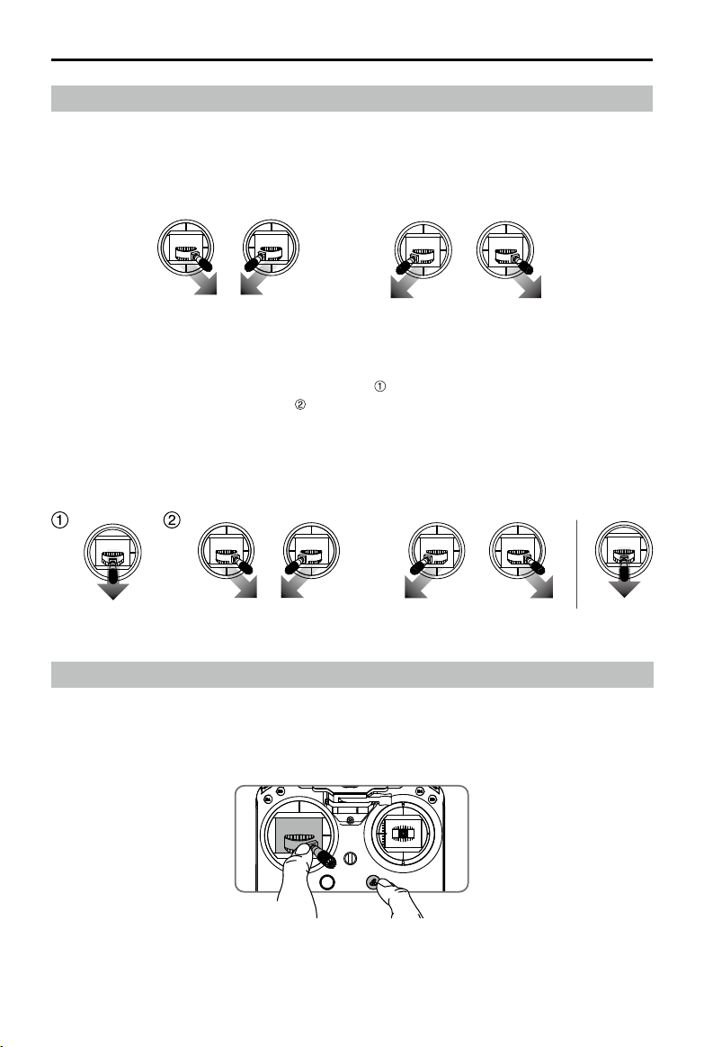
©
2019 DJI All Rights Reserved.
69
MATRICE 200
SERIES V2 User Manual
Starting/Stopping the Motors
Starting Motors
The Combination Stick Command (CSC) is used to start the motors. Push both sticks to the bottom
inner or outer corners to start the motors. Once the motors start spinning, release both sticks simul-
taneously.
OR
Stopping the Motors
There are two ways to stop the motors:
1. When aircraft has landed, push the left stick down , then conduct the same CSC that was used
to start the motors, as shown above . Motors will stop immediately. Release both sticks once
motors stop.
OR
Method 1 Method 2
Stop the Motor Mid-ight
To stop the motors mid-ight, press the RTH button while simultaneously pulling the left stick to the
bottom inner corner.
Stop motors mid-ight will cause the aircraft to crash. The motor can only be
stopped mid-ight when the ight controller detects critical error.
2. When the aircraft has landed, push and hold the left stick down. The motors will stop after three
seconds.
70
©
2019 DJI All Rights Reserved.
MATRICE 200
SERIES V2 User Manual
Flight Test
Takeoff/Landing Procedures
1. Place the aircraft in an open, at area with the battery level indicators facing towards you.
2. Turn on the remote controller, then turn on the Intelligent Flight Battery.
3. Launch DJI Pilot and enter the Camera View.
4. Wait until the Aircraft Status Indicators blink green (GPS) or blink green and blue alternately (RTK,
for the M210 RTK V2 only).
5. If the Intelligent Flight Battery temperature is low, use the self-heating function to heat the
batteries to ensure the temperature is suitable for the aircraft to take off.
6. Turn on the motors using CSC and push the left stick up slowly to take off.
7. To land, hover over a level surface and gently pull down on the left stick to descend.
8. After landing, execute the CSC command or hold the left stick at its lowest position until the
motors stop.
9. Turn off the Intelligent Flight Battery rst, then the remote controller.
It is important to understand basic ight guidelines for the safety of both you and
those around you.
Refer to the Disclaimer and Safety Guidelines for more information.
Only remove the batteries after powering off.
When the Aircraft Status Indicators blink yellow rapidly during ight, the aircraft has entered Failsafe
mode.
A low battery level warning is indicated by the Aircraft Status Indicators blinking red slowly
or rapidly during ight.
Watch our video tutorials for more ight information.
Video Suggestions and Tips
1. Go through the full pre-ight checklist before each ight.
2. Select the desired gimbal operation mode in the DJI Pilot app.
3. Only shoot video when ying in P-mode.
4. Always y in good weather and avoid ying in rain or heavy wind.
5. Choose the camera settings that suit your needs. Settings include photo format and exposure
compensation.
6. Perform ight tests to establish ight routes and preview scenes.
7. Push the control sticks gently to keep the aircraft’s movement smooth and stable.
IP43 Protection Rating
Under stable laboratory conditions, the Matrice 200 Series V2 achieves an IP43 protection rating by
IEC60529 standards when equipped with TB55 Intelligent Flight Batteries. However, this protection
rating is not permanent and may reduce over time after long-term use.
DO NOT y when the amount of rainfall exceeds 10 mm/day.
DO NOT fold the frame arms in the rain.
The angle of inclination of the aircraft body and the ground should not exceed ±30° when y the
aircraft in rainy days.

©
2019 DJI All Rights Reserved.
71
MATRICE 200
SERIES V2 User Manual
Make sure the battery ports, battery compartment ports, battery surfaces, and battery
compartment surfaces are dry before inserting the batteries.
Make sure the battery ports and battery surfaces are free from any liquid before charging the
batteries.
Before packing the aircraft into the carrying case, ensure that it is free from any liquid by wiping it
carefully.
Product warranty does not cover water damage.
The aircraft does not achieve IP43 protection rating in the following circumstances:
Folded frame arms.
Turn the aircraft upside down.
You use batteries other than the M200 Series V2's TB55 Intelligent Flight Batteries.
The cover for the ports and buttons on the rear of the aircraft are not attached correctly.
The external GPS module is in use.
The weatherproong top shell plug is not rmly attached to the top shell.
The microSD card slot cover is not rmly attached.
The aircraft is broken due to various reasons, such as broken aircraft shell, failure of the waterproof
adhesive, etc.

Appendix

©
2019 DJI All Rights Reserved.
73
Aircraft
Dimensions
M200 V2: Unfolded, propellers and landing gears included,
883×886×398 mm
Folded, propellers and landing gears excluded, 722×247×242mm
M210 V2: Unfolded, propellers and landing gears included,
883×886×398 mm
Folded, propellers and landing gears excluded, 722×282×242 mm
M210 RTK V2: Unfolded, propellers and landing gears included,
883×886×427 mm
Folded, propellers and landing gears excluded, 722×282×242 mm
Diagonal Wheelbase 643 mm
Weight
M200 V2: Approx. 4.69 kg (with two TB55 batteries);
M210 V2: Approx. 4.8 kg (with two TB55 batteries);
M210 RTK V2: Approx. 4.91 kg (with two TB55 batteries)
Max Takeoff Weight 6.14 kg
Max Payload
M210 V2: 1.34 kg; M210 RTK V2: 1.23 kg
M200 V2: 1.45 kg
Operating Frequency 2.4000-2.4835 GHz; 5.725-5.850 GHz
EIRP
2.4 GHz: ≤ 26 dBm (NCC/FCC); ≤ 20 dBm (CE/MIC); ≤ 20 dBm (SRRC)
5.8 GHz: ≤ 26 dBm (NCC/FCC); ≤ 14 dBm (CE); ≤ 26 dBm (SRRC)
Hovering Accuracy (P-mode with GPS)
Vertical: ±1.64 feet (±0.5 m) or ±0.33 feet (±0.1 m, Downward Vision
System enabled)
Horizontal: ±4.92 feet (±1.5 m) or ±0.98 feet (±0.3 m, Downward Vision
System enabled)
Hovering Accuracy
(D-RTK, M210 RTK V2)
Vertical: ±0.33 feet (±0.1 m); Horizontal: ±0.33 feet (±0.1 m)
Max Angular Velocity Pitch: 300°/s, Yaw: 120°/s
Max Pitch Angle (Dual Downward Gimbal/
Single Upward Gimbal)
S-mode: 30°; P-mode: 30° (Forward Vision System enabled: 25°);
A-mode: 30°
Max Pitch Angle (Single Downward
Gimbal)
S-mode: 35°; P-mode: 30° (Forward Vision System enabled: 25°);
A-mode: 30°
Max Ascent Speed 16.4 ft/s (5 m/s)
Max Descent Speed (vertical) 9.8 ft/s (3 m/s)
Max Speed (Dual Downward Gimbal/
Single Upward Gimbal)
S-mode/A-mode: 73.8 kph (45.9 mph); P-mode: 61.2 kph (38 mph)
Max Speed (Single Downward Gimbal) S-mode/A-mode: 81 kph (50.3 mph); P-mode: 61.2 kph (38 mph)
Max Service Ceiling Above Sea Level 9842 feet (3000 m, with 1760S propellers)
Max Wind Resistance 39.4 ft/s (12 m/s)
Max Flight Time (with two TB55 batteries)
M200 V2: 38 min (no payload), 24 min (takeoff weight: 6.14 kg)
M210 V2: 34 min (no payload), 24 min (takeoff weight: 6.14 kg)
M210 RTK V2: 33 min (no payload), 24 min (takeoff weight: 6.14 kg)
Motor Model DJI 3515
Propeller Model 1760S
Appendix
Specications
74
©
2019 DJI All Rights Reserved.
MATRICE 200
SERIES V2 User Manual
Supported DJI Gimbals Zenmuse X4S/X5S/X7/XT/XT2/Z30/XT S
Supported Gimbal Congurations
M200 V2: Single Downward Gimbal
M210 V2 / M210 RTK V2: Single Downward Gimbal (connected to Gimbal
Connector I), Dual Downward Gimbals, Single Upward Gimbal
Ingress Protection Rating IP43
GNSS
M200 V2 / M210 V2: GPS+GLONASS;
M210 RTK V2: GPS+GLONASS+BeiDou+Galileo
Operating Temperature -4° to 122° F (-20° to 50° C)
Beacons
Power Avg. 0.6 W
Luminous Intensity Min. Angle: 55 cd; light intensity: 157 cd
Max. Visible Distance 5000 m (with good air quality and high visibility)
Remote Controller (GL900A)
Operating Frequency 2.4000-2.4835 GHz; 5.725-5.850 GHz
Max Transmitting Distance
(unobstructed, free of interference)
NCC/FCC: 5 mi (8 km); CE/MIC: 3.1 mi (5 km); SRRC: 3.1 mi (5 km)
EIRP
2.4 GHz: ≤ 26 dBm (NCC/FCC); ≤ 20 dBm (CE/MIC); ≤ 20 dBm (SRRC)
5.8 GHz: ≤ 26 dBm (NCC/FCC); ≤ 14 dBm (CE); ≤ 26 dBm (SRRC)
Video Output Ports USB, HDMI, SDI
Power Supply Extended Intelligent Battery (Model: WB37-4920mAh-7.6V)
Charging DJI charger or DJI charging hub
Output Power (max) 13 W (Without supplying power to monitor)
USB Power Supply 1 A
5.2 V (max)
CrystalSky Monitor (Excluded in M200
V2)
DJI CrystalSky 7.85inch, Resolution: 2048×1536;
Brightness: 2000 cd/m
2
; Operating System: Android 5.1; Storage: ROM
128GB
Operating Temperature -4° to 122° F (-20° to 50° C)
Optimal Storage Temperature 72° to 86° F (22° to 30° C)
Charging Temperature 32° to 104° F (0° to 40° C)
Downward Vision System
Velocity Range <32.8 ft/s (10 m/s) at the height of 6.56 feet (2 m)
Altitude Range <32.8 feet (10 m)
Operating Range <32.8 feet (10 m)
Operating Environment Surfaces with clear patterns and adequate lighting (>15 lux)
Ultrasonic Sensor Operating Range 0.33-16.4 feet (0.1-5 m)
Ultrasonic Sensor Operating Environment
Non-absorbing material, rigid surfaces (thick indoor carpeting will
adversely affect performance)
Forward Vision System
Obstacle Sensing Range 2.3-98.4 feet (0.7-30 m)
FOV Horizontal: 60°; Vertical: 54°
Operating Environment Surfaces with clear patterns and adequate lighting (> 15 lux)

©
2019 DJI All Rights Reserved.
75
MATRICE 200
SERIES V2 User Manual
Upward Infrared Sensing System
Obstacle Sensing Range 0-16.4 feet (0-5 m)
FOV ±5°
Operating Environment Large, diffuse, and reective obstacles (reectivity >10%)
Intelligent Flight Battery (TB55-7660mAh-22.8V)
Capacity 7660 mAh
Voltage 22.8 V
Battery Type LiPo 6S
Energy 174.6 Wh
Net Weight (Single One) Approx. 885 g
Operating Temperature -4° to 122° F (-20° to 50° C)
Optimal Storage Temperature 72° to 86° F (22° to 30° C)
Charging Temperature 41° to 104° F (5° to 40° C)
Max Charging Power 180 W
Charger (IN2C180)
Voltage 26.1 V
Rated Power 180 W
Charging Hub (IN2CH)
Input Voltage 26.1 V
Input Current 6.9 A
Firmware Update
Use the DJI Pilot app or the DJI Assistant 2 for Matrice to update the remote controller, aircraft and
other connected DJI devices.
For the Zenmuse X5S, X4S and X7, the aircraft and gimbal rmware will be updated simultaneously
via DJI Assistant 2 for Matrice or the DJI Pilot app.
For the Zenmuse Z30, XT, XT S and XT2, only aircraft rmware can be updated via DJI Assistant 2
for Matrice or the DJI Pilot app. Gimbal rmware must be updated via a microSD card.
Using DJI Pilot
1. Ensure that there is good connection between the aircraft and remote controller and other DJI
devices used with the aircraft such as a D-RTK 2 Mobile Station for Matrice Series, and that all
the devices are powered on.
2. Go to the app. A prompt will appear if new firmware is available for download. Follow the
on-screen instructions to update the firmware. Make sure to connect to the Internet when
downloading the rmware.
Using DJI Assistant 2 for Matrice
Connect the remote controller to the software and then run a rmware update for all the connected
DJI devices. Users can also connect each device to the software to update its own rmware.
1. Power on the device and connect it to the software.
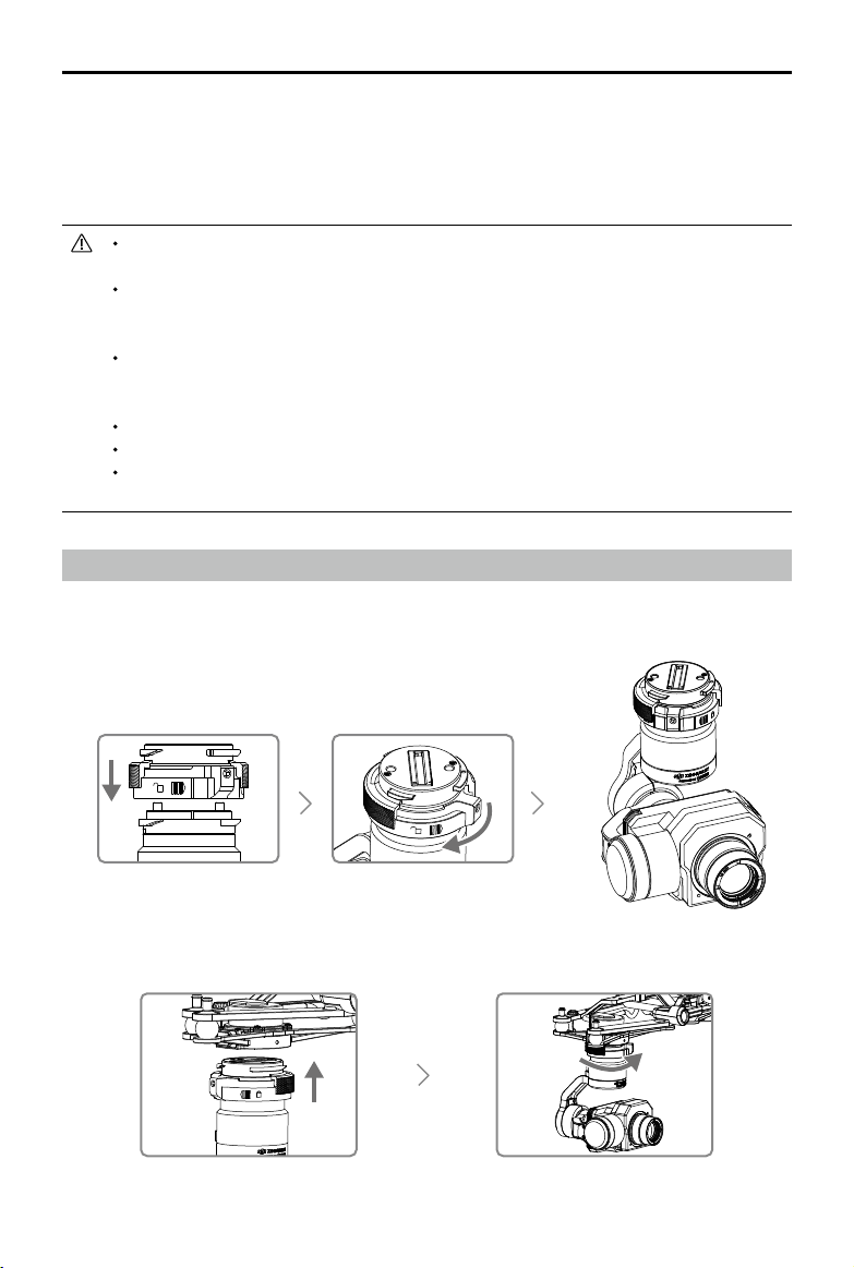
76
©
2019 DJI All Rights Reserved.
MATRICE 200
SERIES V2 User Manual
2. Click the corresponding device name and then the rmware update tag.
3. Select the rmware version required. Make sure to connect to the Internet when downloading the
rmware.
4. Restart the device after the rmware update is complete.
The battery rmware is included in the aircraft rmware. Be sure to update all the batteries'
rmware.
The rmware update will take around 15 minutes. It is normal that the gimbal will go limp, the
aircraft status indicator blinks abnormally when the aircraft reboots. Wait patiently until the
update is complete.
During an update, the aircraft will sound a quick single beep continuously. The warning
sound will then alternate between a longer beep and a quick double beep once the
update is complete. Restart the aircraft after the rmware update is complete.
If the warning sound turns into a long beep, retry the update.
The battery level should be above 30% for the rmware update process.
When using DJI Pilot to update, you may disconnect the aircraft and the mobile device
once the update is more than 30% completed. No Internet connection is required.
Using the Zenmuse XT Gimbal and Camera
The Zenmuse XT Gimbal Adapter is required when mounting the Zenmuse XT gimbal to the aircraft.
1. Attach the Zenmuse XT gimbal adapter onto the Zenmuse XT gimbal.
2. Mount the Zenmuse XT onto the aircraft by securing the gimbal adapter.
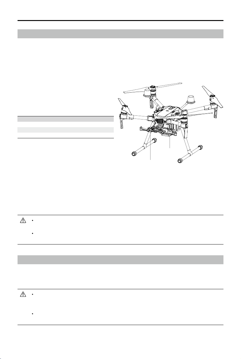
©
2019 DJI All Rights Reserved.
77
MATRICE 200
SERIES V2 User Manual
Using the Upward Gimbal and GPS Kit
The M210 V2/M210 RTK V2 supports upward gimbal. The GPS kit is required to obtain better GPS
signal when an upward gimbal is used on the M210 V2 aircraft. Refer to the manuals for the Single
Upward Gimbal Connector and GPS Kit on installation and usage.
The GPS kit has an IP43 ingress protection. However, the aircraft will not retain its IP43
rating if the GPS kit is installed. Users can customize a waterproof rear port cover to
ensure ingress protection.
The M210 V2/M210 RTK V2 supports the simultaneous use of an upward gimbal and a
downward gimbal. The upward gimbal should be connected to Gimbal Connector I only.
Dual Downward Gimbals
The M210 V2/M210 RTK V2 supports dual downward gimbals.
Using the Dual Downward Gimbals
All Zenmuse X5S, X4S, XT, X7, XT2, and Z30 gimbals are supported. You can mount them to the
Gimbal Connector I and Gimbal Connector II as shown below:
Gimbal Connector II Gimbal Connector I
Zenmuse XT Zenmuse X4S/X5S/X7/XT2/Z30
Zenmuse Z30 Zenmuse X4S/X5S/X7/XT/XT2/XT S
Zenmuse XT S Zenmuse X4S/X5S/X7/Z30
Please note that Gimbal Connector II can be mounted with the Zenmuse XT, XT S and Z30 only.
Gimbal Connector I and Gimbal Connector II cannot be mounted with two of the same Zenmuse
gimbals.
Gimbal Connector I's camera view will show on the main interface in the DJI Pilot app, while Gimbal
Connector II's camera view will show on the assistant interface. You can switch between them.
When using the Zenmuse Z30 and X7 cameras together, they might obstruct each other's
motion at certain angles.
If using only one camera be sure to install the gimbal and camera on Gimbal Connector I
and not on Gimbal Connector II.
Gimbal
Connector II
Gimbal
Connector I
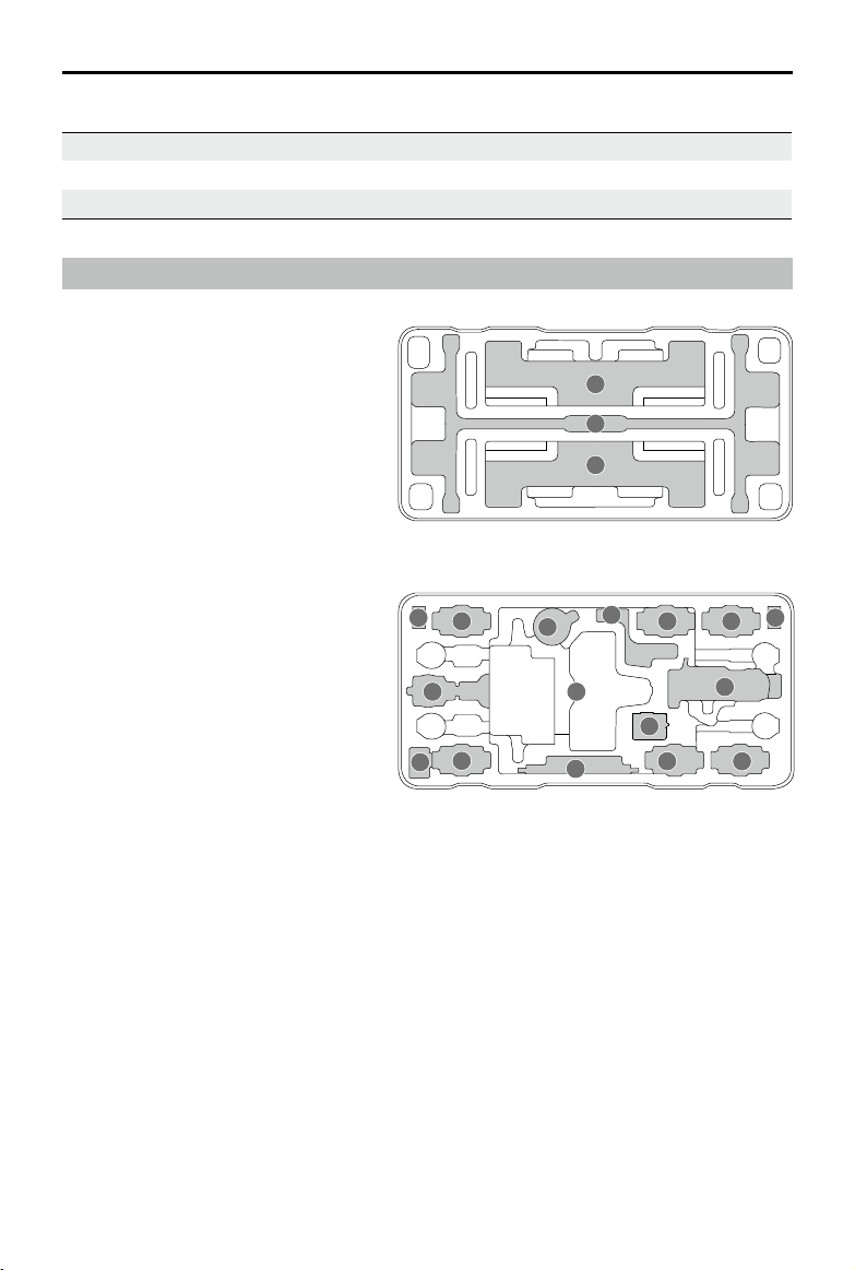
78
©
2019 DJI All Rights Reserved.
MATRICE 200
SERIES V2 User Manual
Carrying Box Descriptions
1
2
2
1. Landing Gear × 2
2. Propeller Pair × 4
3. Aircraft
4. Remote Controller
5. CrystalSky Monitor/iPad
6. Intelligent Flight Battery
7. Wb37 Intelligent Battery
8. In2ch Charging Hub
9. WCH2 Charging Hub
10. Battery Charger
11. Gimbal and Camera (X5S/Z30)
12. Mobile Device Holder
13. Remote Controller Strap/Intelligent Flight Battery
14. Power Cable/Intelligent Flight Battery
15. Accessory Box/Intelligent Flight Battery
GPS Kit Indicator Descriptions
Blinking Blue Self-checking, or positioning nished but not used.
Blinking Green Slowly Positioning nished and data from GPS kit used.
Red Error
4
5
6
13
66
14
7
8
10
11
9
7
15
3
12

Copyright © 2019 DJI All Rights Reserved.
This content is subject to change.
Download the latest version from
http://www.dji.com/matrice-200-series-v2
If you have any questions about this document, please contact DJI by
sending a message to
.
DJI Support
https://www.dji.com/support