Loading ...
Loading ...
Loading ...
Operation
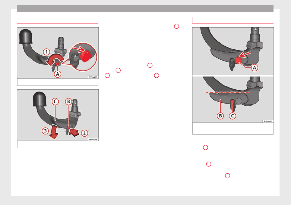
Placing in standby position
Fig. 214 Step 1.
Fig. 215 Step 2.
Before assembling it, place the detachable
b
al
l
in the standby position with the follow-
ing two steps.
Step 1.
●
Turn the key in the direction of arrow
1
un-
ti
l
the p
art of the key with the holes reaches
the top position ››› Fig. 214 (arrow).
Step 2.
●
Grip the detachable ball below the protec-
tive cover.
●
Press the release bolt
B
in the direction of
arr
o
w
2
, and at the same time press lever
C
in the direction of arrow
3
as far as it will
g
o ›
›
› Fig. 215.
The lever will remain blocked in this position.
Standby position
Fig. 216 Standby position: Position of the lev-
er and the r
el
e
ase bolt.
Standby position adjusted properly
●
Key
A
›
›
› Fig. 216
is in the released posi-
tion (the part of the key with the holes is fac-
ing upwards).
●
Lever
B
›
›
› Fig. 216
is in the bottom posi-
tion.
●
The release bolt
C
›
›
› Fig. 216
can be
moved.
238
Loading ...
Loading ...
Loading ...