Loading ...
Loading ...
Loading ...
6
USER’S MANUAL /
FUSE
• + BATT (7÷20 VDC): terminal for connecting the positive power supply pole to S8 DSP.
• GND (Ground): terminal to connect the processor’s power supply negative pole. Connect the negative battery
cable or a cable connected to the car’s chassis.
To fix the ground connection (-) correctly use a screw already available on the vehicle’s chassis; remove any paint
or grease residue if necessary, ensuring that there is a continuity between the negative terminal (-) of the battery
and the fixing point. If possible, connect all audio components grounds to the same point as this solution is
necessary to reduce the majority of parasitic noises which may arise during reproduction.
• REM IN: terminal to turn on the S8 DSP via the Remote Out output of the audio signal source. The applied voltage
must be between 6 and 20 VDC. If you are using a source with BTL amplified outputs, the S8 DSP can turn on
automatically
(see section 5.1)
, so you will not need to connect the REM IN terminal.
• REM OUT: toutput terminal for the remote turn on of other devices/amplifiers connected to the S8 DSP. The processor
takes 3 seconds to provide the REM OUT to the output, but you can manually set this delay with the software
(see section . 8.2.7.2.2)
. This output has a current capacity of 150 mA and can drive an automotive relay.
• IN SEL: to switch to the selected input via the software
(see section 8.2.7.1)
.
This command is active by connecting the terminal to MEM GND
(see section 5.1)
.
• MEM SEL1 - MEM SEL 2: allows the selection of the memories of the S8 DSP
(see section. 8.10)
.
This command is active by connecting the terminals to MEM GND
(see section 5.1)
according to the following table:
• MEM GND: ensures
1 if connected to IN SEL
(see section 5.1)
to switch to the selected input through the control software
(see section 8.2.7.1)
,
2 if connected to MEM SEL1 - MEM SEL 2
(see section. 5.1)
the S8 DSP memories selection
(see section. 8.10)
4
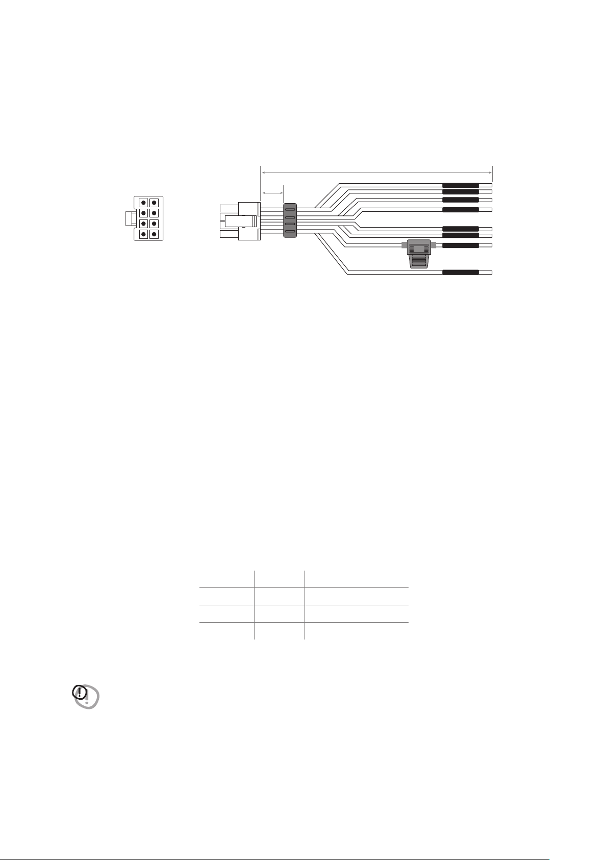
PWR/REM:
The cable is provided to manage the power supply and the various control connections.
WIRE SIZE 20 AWG
1A
+ BATT
REM OUT
GND
MEM/SEL2
MEM/SEL1
REM IN
MEM GND
IN SEL
MEM SEL1 MEM SEL2 MEMORY SELECTION
NC NC A*
MEM GND NC B
NC MEM GND C
MEM GND MEM GND D
WARNING: the system returns to memory A when MEM SEL 1, MEM SEL 2 terminals are disconnected from
MEM GND, so if you want to use this function it is advisable to finalize the device or assign memory A
as a favorite preset to the input used
(see section sez.8.2.7.3.).
190 mm / 7.48 in.
6 mm
0.23 in.
4
REAR VIEW
BlueBlue/White
BlackPink
BlackYellow
WhiteWhite
Pink
White/Blue
White
Black
Blue
Yellow
Black
White
Loading ...
Loading ...
Loading ...