hertz-audio.com
USER’S
MANUAL
S8 DSP
Digital Interface Processor
rev. 1a

2
USER’S MANUAL /
Index
1. PRODUCT DESCRIPTION ..................................................................................................................................................................................3
2. PACKAGING CONTENT .....................................................................................................................................................................................4
3. S8 DSP INSTALLATION ....................................................................................................................................................................................4
4. CONNECTIONS PANEL ..................................................................................................................................................................................... 5
1 USB ........................................................................................................................................................................................................ 5
2 LED STATUS ............................................................................................................................................................................................. 5
3 LED BT......................................................................................................................................................................................................5
4 PWR/REM. ..............................................................................................................................................................................................6
5 OUTPUT .................................................................................................................................................................................................... 7
6 PRE IN - DIGITAL IN ................................................................................................................................................................................7
7 SPEAKER IN ............................................................................................................................................................................................. 8
5. CONNECTIONS ..................................................................................................................................................................................................9
5.1 POWER SUPPLY AND REMOTE TURN ON ...........................................................................................................................................9
5.2 INPUT SIGNALS .....................................................................................................................................................................................10
5.2.1 PRE IN - Ch1/Ch6 STEREO ANALOG SIGNAL ..........................................................................................................................10
5.2.2 DIGITAL IN - S/PDIF DIGITAL INPUT .........................................................................................................................................10
5.2.3 SPEAKER IN - CH1/CH6 (ALTO LIVELLO) .................................................................................................................................11
5.3 OUTPUT SIGNALS . ................................................................................................................................................................................12
5.4 CONNECT S8 DSP TO THE PC/MAC ....................................................................................................................................................12
6. GUIDE FOR INSTALLING S8 DSP SOFTWARE .............................................................................................................................................13
6.1 PC WINDOWS ........................................................................................................................................................................................13
6.1.1 INSTALLAZIONE SOFTWARE .....................................................................................................................................................13
6.1.2 SOFTWARE UNINSTALL .............................................................................................................................................................15
6.2 MAC OS ..................................................................................................................................................................................................16
6.2.1 macOS ..........................................................................................................................................................................................16
6.3 S8 DSP APP INSTALLATION ON MOBILE DEVICES ............................................................................................................................17
6.3.1 ANDROID .....................................................................................................................................................................................17
6.3.2 APPLE iOS ...................................................................................................................................................................................17
7. S8 DSP SET UP WITH PC/MAC .....................................................................................................................................................................18
7.1 OFFLINE MODE .....................................................................................................................................................................................18
7.1.1 CREATE NEW SETUP ..................................................................................................................................................................19
7.1.2 OPEN A SAVED SETUP ...............................................................................................................................................................21
7.2 CONNECT USB MODE ...........................................................................................................................................................................21
7.2.1 CONNECTION VIA USB CABLE ..................................................................................................................................................21
7.3 CONNECT BT MODE ..............................................................................................................................................................................23
7.4 S8 DSP DEFAULT SETUP ......................................................................................................................................................................25
7.4.1 INPUTS .........................................................................................................................................................................................25
7.4.2 OUTPUTS .....................................................................................................................................................................................25
7.5 I/O CONFIGURATION WIZARD .............................................................................................................................................................26
7.5.1 SYSTEM SELECTION ...................................................................................................................................................................25
7.5.2 SPEAKER SELECTION .................................................................................................................................................................28
7.5.3 PASSIVE CROSSOVER SELECTION - OUTPUT CHANNELS ASSIGNMENT /OUTPUT CHANNELS NAME ............................29
7.5.4 ANALOG INPUTS CONFIGURATIONS .........................................................................................................................................31
7.5.5 ANALOG INPUTS-OUTPUTS ROUTING ......................................................................................................................................32
7.5.6 INPUTS SENSITIVITY SETUP .......................................................................................................................................................35
7.5.7 INPUTS EQ SETUP (ANALOG INPUTS EQUALIZER) ..................................................................................................................36
7.5.8 WIZARD COMPLETED.................................................................................................................................................................38
8. S8 DSP SETUP USING A PC/MAC .................................................................................................................................................................39
8.1 MAIN MENU “FILE” ...............................................................................................................................................................................40
8.2 MAIN MENU “SETTINGS” ......................................................................................................................................................................45
8.3 MAIN MENU “MEMORY” ......................................................................................................................................................................52
8.4 CHANNEL MAP .....................................................................................................................................................................................53
8.5 CHANNEL LIST ......................................................................................................................................................................................53
8.6 CROSSOVER SETTINGS .........................................................................................................................................................................54
8.7 OUTPUT EQUALIZER .............................................................................................................................................................................57
8.8 OUTPUT LEVEL ......................................................................................................................................................................................58
8.9 SELECT INPUT .......................................................................................................................................................................................59
8.10 MEMORY ...............................................................................................................................................................................................59
8.11 DEVICE INFO ..........................................................................................................................................................................................59
9. TROUBLESHOOTING ......................................................................................................................................................................................60
9.1 BACKGROUND NOISE ...........................................................................................................................................................................60
9.2 FIRMWARE UPGRADE ..........................................................................................................................................................................61
10. TECHNICAL SPECIFICATIONS ........................................................................................................................................................................63
3
USER’S MANUAL /
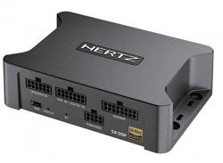
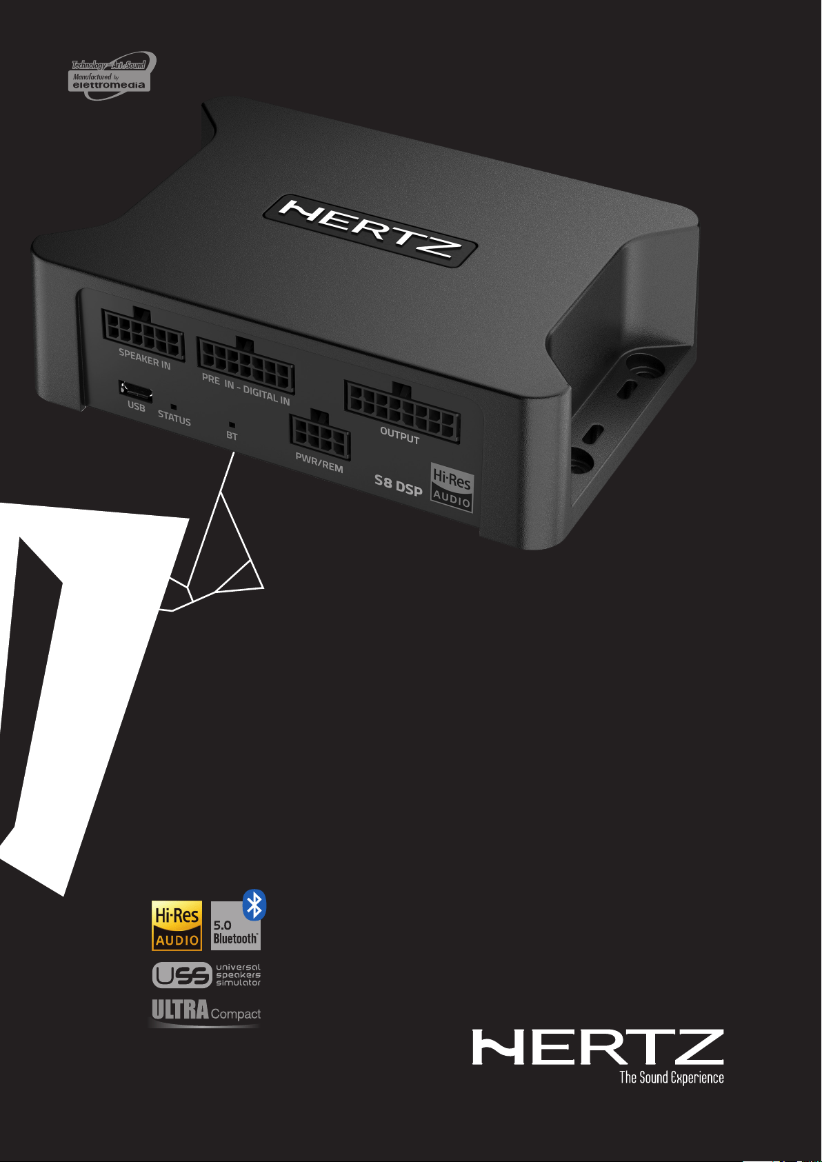
1. PRODUCT DESCRIPTION
S8 DSP is a digital signal processor essential to maximize the acoustic performance of your car audio system. It features
13 signal inputs, 6 Hi-Level, 6 Pre-In and 1 S/PDIF 24bit/96kHz digital coaxial and provides 8 PRE OUT analog outputs.
Each input channel is equipped with a 7-band adjustable parametric equalizer, and each output with a 15-band
adjustable parametric equalizer, 122-frequency steps electronic crossover, BUTTERWORTH, LINKWITZ or BESSEL with
slopes from 6 to 30 dB and a digital time delay line.
It is provided with a software to configure the product in both Windows OS and macOS versions, as well as in an APP
version that can be downloaded online for both Android and Apple mobile devices.
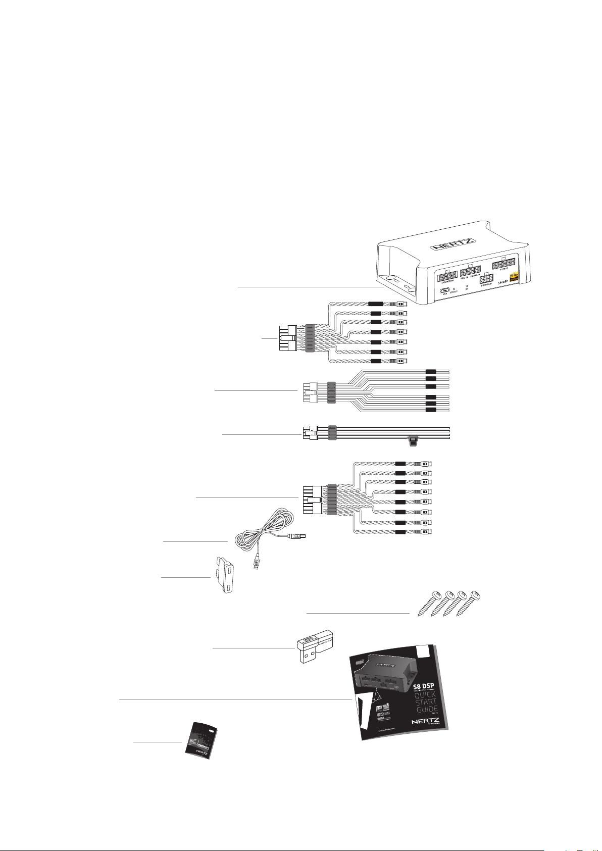
- 1 - Fuse 1 A:
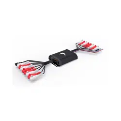
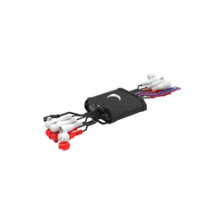
2. PACKAGING CONTENTS
- Multipolar cable, Output:
- USB cable 1.8 m:
- 4 self-tapping, cross-head fixing screws 3,5 x 25 mm:
- USB Memory Dongle Setup:
S8 DSP Software (Windows)
This User’s manual (.pdf)
Audio Test tracks
- QSG:
- Warranty
- Signal Interface Processor S8 DSP
- Multipolar cable, Speaker IN:
- Multipolar cable, Pre-IN/Digital-IN:
- Multipolar cable PWR/REM:
IN 1
IN 2
IN 3
IN 4
IN 5
IN 6
IN 6
IN 5
IN 4
IN 3
IN 2
IN 1
S/PDIF-IN
FUSE
IN 7
IN 6
IN 5
IN 4
IN 2
IN 1
IN 8
IN 3
1/2
S8 DSP
4
USER’S MANUAL /
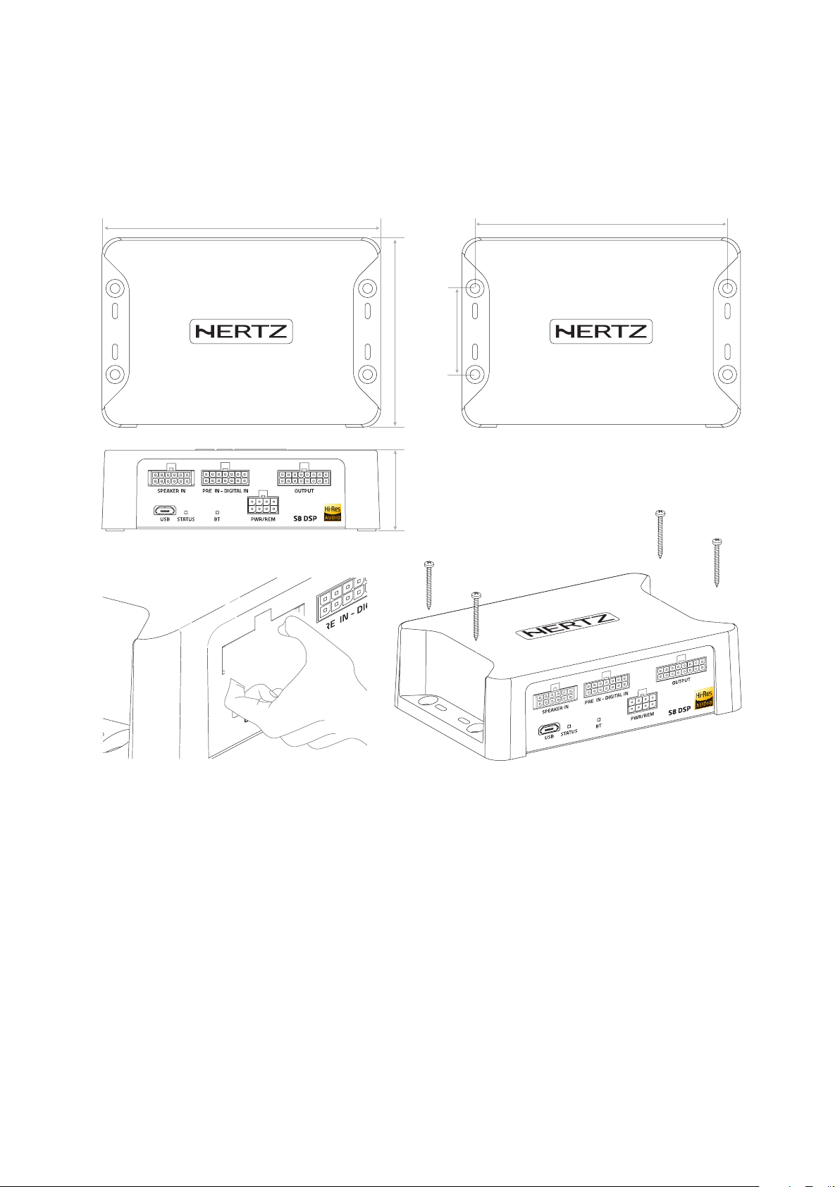
3. S8 DSP INSTALLATION
External dimensions
Mounting dimensions
Installation
WARNING for all INPUT/OUTPUT cables
88,3 mm / 3.47 in.
130 mm / 5.11 in.
40,5 mm / 1.59 in.
118 mm / 4,6 in.
OK
36,8 mm / 1.44 in.
3
5
USER’S MANUAL /
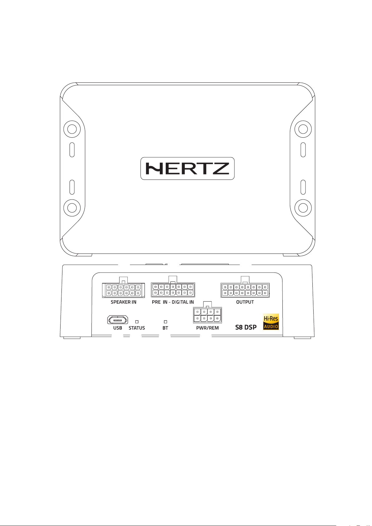
4. CONNECTIONS PANEL - DESCRIPTION
1
2
3
31
7
4
5
2
6
USB
Connection socket (Micro USB female) to connect the processor to a PC/MAC and manage the functions via the S8 DSP
software
(see sect. 5.4)
. The connection standard is compatible with USB 1.1/ 2.0/3.0.
LED STATUS:
Through the LED lighting it is possible to identify the status of the processor:
Green: S8 DSP is on and functioning normally.
Light green (BT LED TURNED OFF): S8 DSP is connected to the PC/MAC via USB.
Green/blue flashing: S8 DSP is communicating data with the control device via software
(see sect. 7.2 - 7.3)
.
Purple: S8 DSP is configured with DIGITAL IN input but is not detecting a digital signal
(see sect. 8.9)
.
Orange: S8 DSP is signalling the presence of clipping on the analog input
(see sect. 7.5.6)
.
Red: S8 DSP is reporting a malfunction or breakdown.
White: S8 DSP is in UPGRADE mode
(see sect. 9.2)
.
LED BT:
Through the LED lighting it is possible to identify the status of the processor’s bluetooth connection,
BLU flashing: S8 DSP is waiting to pair with a Bluetooth device
(see sect. 7.3 - 8.1.6)
.
BLUE: S8 DSP is connected with a Bluetooth device
(see sect. 7.3 - 8.1.6)
.
Turned off: S8 DSP is reporting a malfunction of the Bluetooth module or connected via USB.
4
6
USER’S MANUAL /
FUSE
• + BATT (7÷20 VDC): terminal for connecting the positive power supply pole to S8 DSP.
• GND (Ground): terminal to connect the processor’s power supply negative pole. Connect the negative battery
cable or a cable connected to the car’s chassis.
To fix the ground connection (-) correctly use a screw already available on the vehicle’s chassis; remove any paint
or grease residue if necessary, ensuring that there is a continuity between the negative terminal (-) of the battery
and the fixing point. If possible, connect all audio components grounds to the same point as this solution is
necessary to reduce the majority of parasitic noises which may arise during reproduction.
• REM IN: terminal to turn on the S8 DSP via the Remote Out output of the audio signal source. The applied voltage
must be between 6 and 20 VDC. If you are using a source with BTL amplified outputs, the S8 DSP can turn on
automatically
(see section 5.1)
, so you will not need to connect the REM IN terminal.
• REM OUT: toutput terminal for the remote turn on of other devices/amplifiers connected to the S8 DSP. The processor
takes 3 seconds to provide the REM OUT to the output, but you can manually set this delay with the software
(see section . 8.2.7.2.2)
. This output has a current capacity of 150 mA and can drive an automotive relay.
• IN SEL: to switch to the selected input via the software
(see section 8.2.7.1)
.
This command is active by connecting the terminal to MEM GND
(see section 5.1)
.
• MEM SEL1 - MEM SEL 2: allows the selection of the memories of the S8 DSP
(see section. 8.10)
.
This command is active by connecting the terminals to MEM GND
(see section 5.1)
according to the following table:
• MEM GND: ensures
1 if connected to IN SEL
(see section 5.1)
to switch to the selected input through the control software
(see section 8.2.7.1)
,
2 if connected to MEM SEL1 - MEM SEL 2
(see section. 5.1)
the S8 DSP memories selection
(see section. 8.10)
4
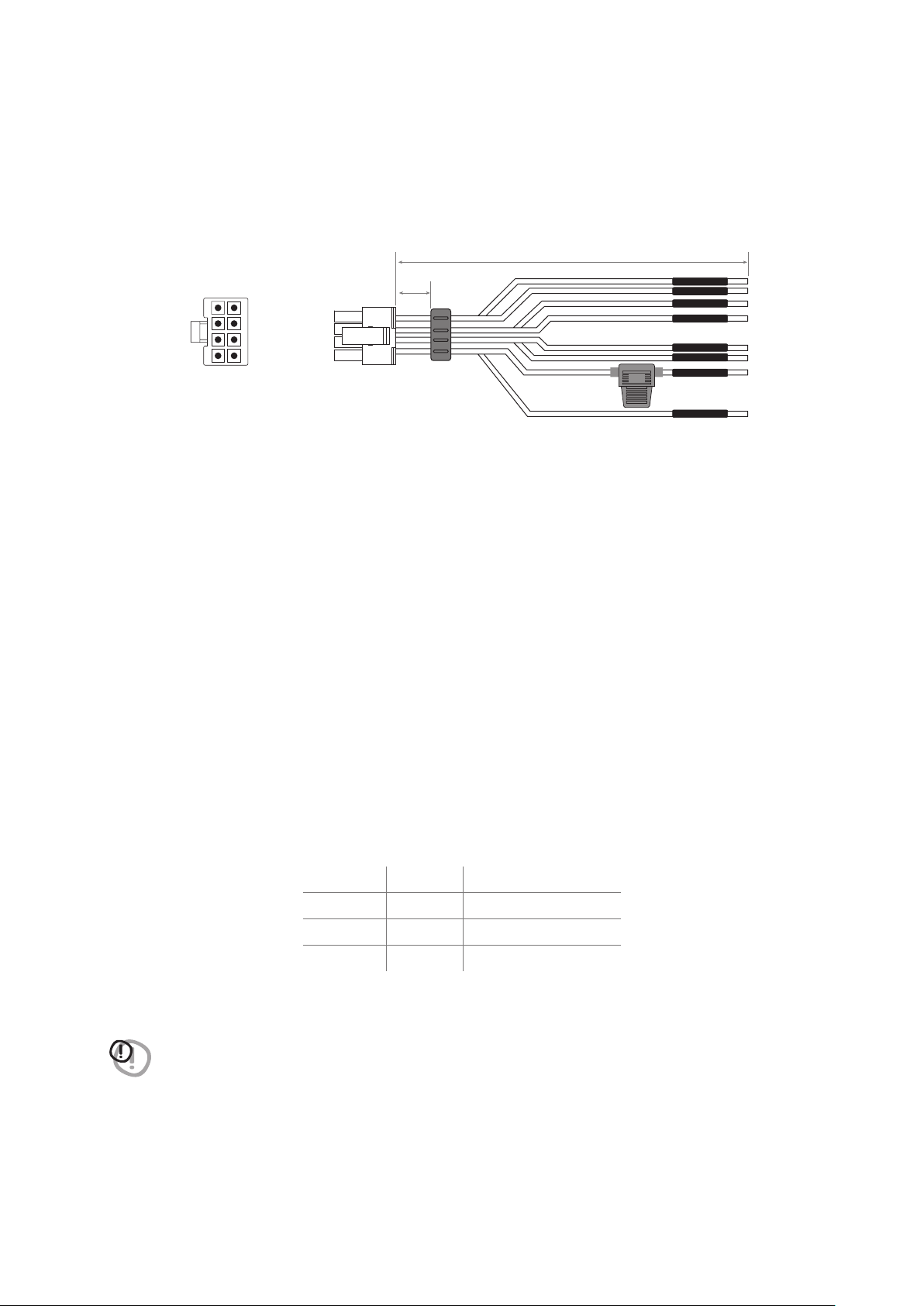
PWR/REM:
The cable is provided to manage the power supply and the various control connections.
WIRE SIZE 20 AWG
1A
+ BATT
REM OUT
GND
MEM/SEL2
MEM/SEL1
REM IN
MEM GND
IN SEL
MEM SEL1 MEM SEL2 MEMORY SELECTION
NC NC A*
MEM GND NC B
NC MEM GND C
MEM GND MEM GND D
WARNING: the system returns to memory A when MEM SEL 1, MEM SEL 2 terminals are disconnected from
MEM GND, so if you want to use this function it is advisable to finalize the device or assign memory A
as a favorite preset to the input used
(see section sez.8.2.7.3.).
190 mm / 7.48 in.
6 mm
0.23 in.
4
REAR VIEW
BlueBlue/White
BlackPink
BlackYellow
WhiteWhite
Pink
White/Blue
White
Black
Blue
Yellow
Black
White
7
USER’S MANUAL /
6
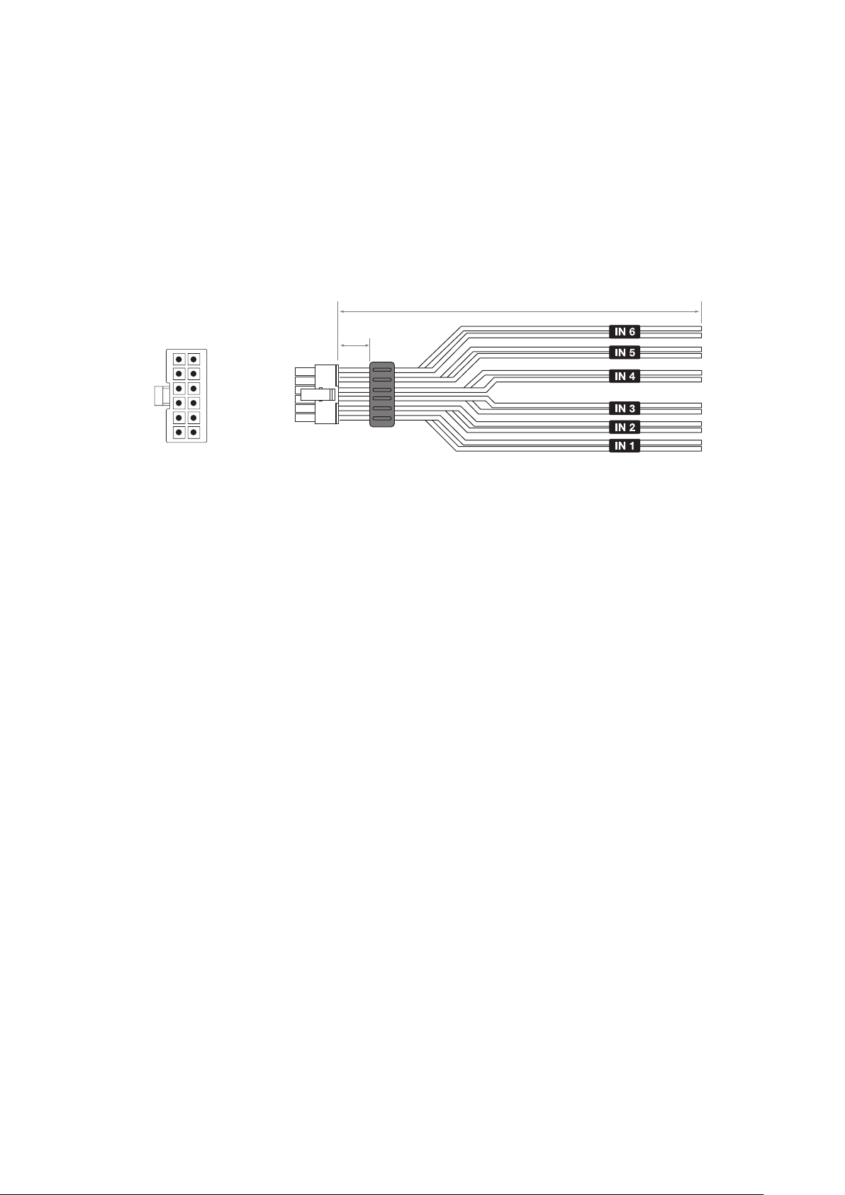
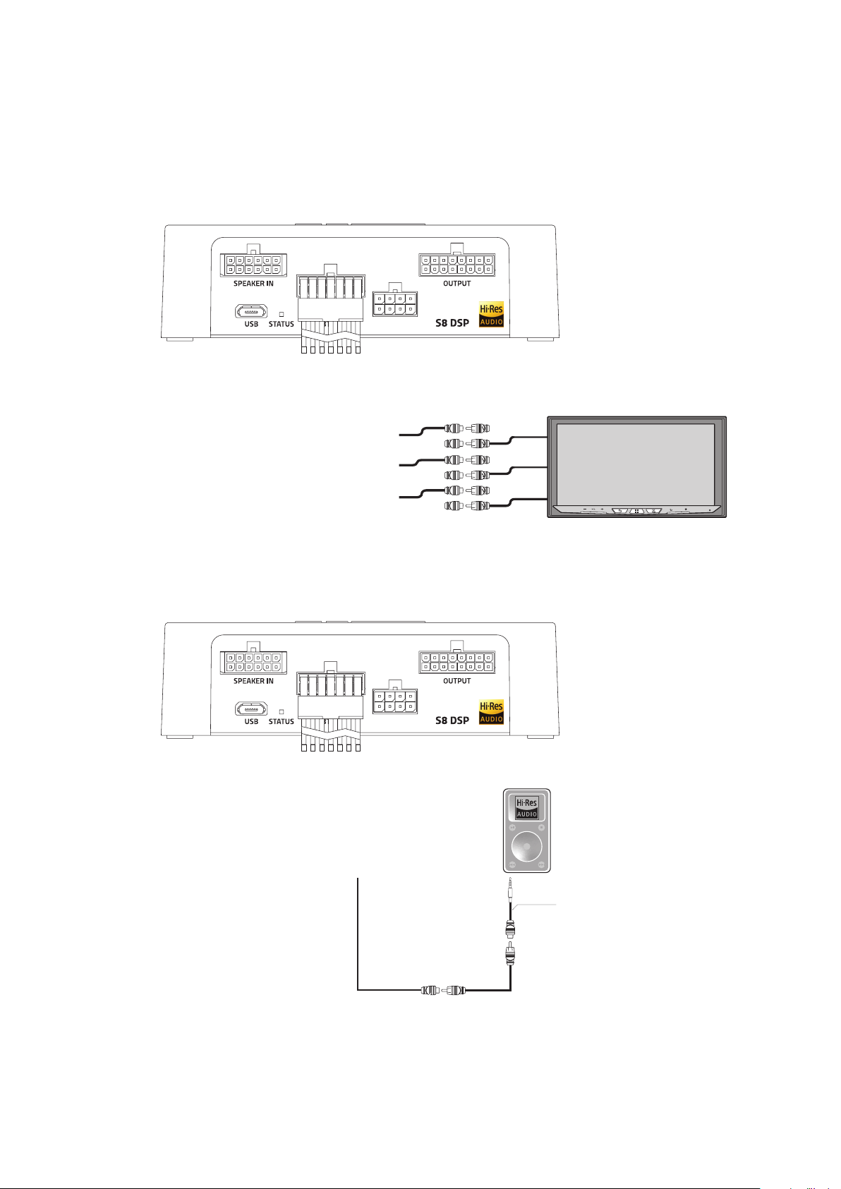
PRE IN - DIGITAL IN:
• PRE IN. ANALOG (RCA) low level input
IN1 - IN2 - IN3 - IN4 - IN5 - IN6
The cable is provided to connect the preamplified signal outputs from the analog Master source with RCA connectors.
Through the software it will be possible to specialize the inputs by assigning the desired input
(see section. 7.5.4 - 7.5.5 - 8.2.2)
.
Input sensitivity adjustable from 0,8 to 6 V RMS
• DIGITAL IN. S/PDIF digital input
S/PDIF-IN
The cable is provided to connect the signal from your source with digital output via a specific coaxial cable for digital
signals with RCA connection. S8 DSP accepts PCM signals at its input with a maximum sampling frequency up to
96 kHz 24 bit, therefore it is not possible to reproduce DOLBY DIGITAL (AC3) encoded multichannel signals from
audio/video sources (such as the audio of a film in DVD) or DTS.
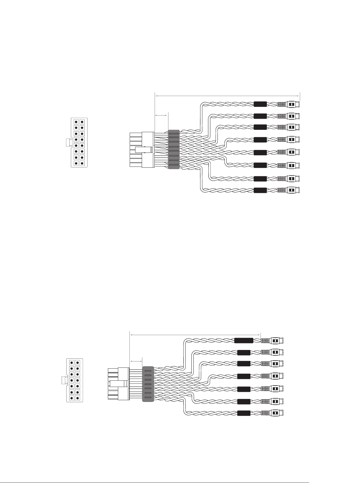
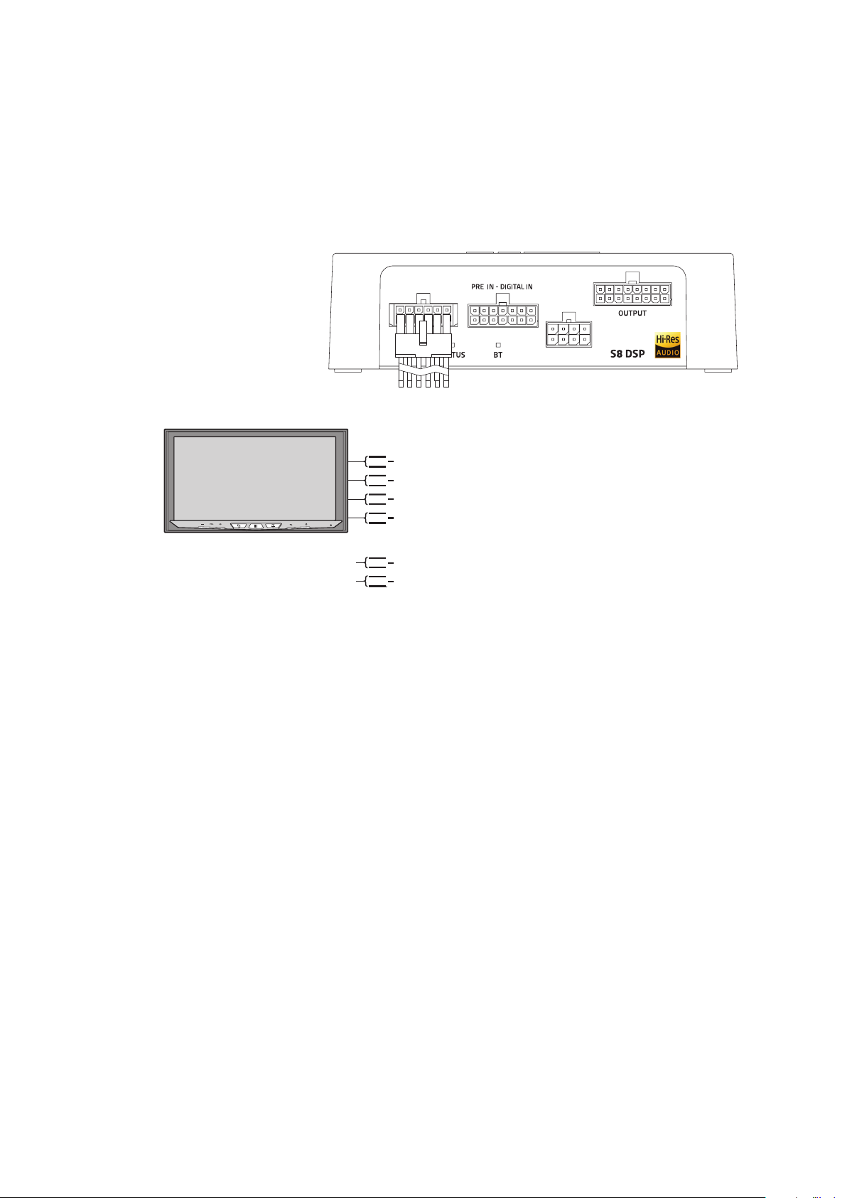
OUTPUT Low level analog signal (4 Volt RMS).
Ch1 - Ch2 - Ch3 - Ch4 - Ch5 - Ch6 - Ch7 - Ch8
The cable is provided to be connected to the RCA cables going to the system amplifiers.
5
4
IN 6
IN 5
IN 4
IN 3
IN 2
IN 1
S/PDIF-IN
200 mm / 7.87 in.
White
White/Black
Gray
Gray/Black
Green
Green/Black
Purple
Purple/Black
Blue
Blue/Black
Brown
Brown/Black
Orange
Orange/Nero
WIRE SIZE 20 AWG
6 mm
0.23 in.
REAR VIEW
OUT 8 -
OUT 6 -
OUT 4 -
OUT 2 -
OUT 8 +
OUT 6 +
OUT 4 +
OUT 2 +
OUT 7 -
OUT 5 -
OUT 3 -
OUT 1 -
OUT 7 +
OUT 5 +
OUT 3 +
OUT 1 +
WIRE SIZE 20 AWG
200 mm / 7.87 in.
6 mm
0.23 in.
OUT 8
OUT 4
OUT 6
OUT 2
OUT 7
OUT 3
OUT 5
OUT 1
REAR VIEW
IN 6 -
IN 4 -
IN 2 -
IN 6 +
IN 4 +
IN 2 +
IN 5 -
IN 3 -
IN 1 -
S/PDIF + S/PDIF -
IN 5 +
IN 3 +
IN 1 +
8
USER’S MANUAL /
White
White/Black
Gray
Gray/Black
Green
Green/Black
Purple
Purple/Black
Blue
Blue/Black
Brown
Brown/Black
190 mm / 7.48 in.
6 mm
0.23 in.
7
SPEAKER IN high level input:
IN1 - IN2 - IN3 - IN4 - IN5 - IN6
The cable is provided to be connected to the amplified signals coming from the analog Master source. Through the
software it will be possible to specialize the inputs by assigning the desired input
(see sections 7.5.4 - 7.5.5 - 8.2.2)
.
Input sensitivity adjustable from 2,5 to 21 VRMS.
Remark:
when connecting a speaker input cable, use solderless crimped Faston terminals.
WIRE SIZE 20 AWG
REAR VIEW
White White/Black
Green Green/Black
Blue Blue/Black
Gray Gray/Black
Purple Purple/Black
Brown Brown/Black
4
9
USER’S MANUAL /
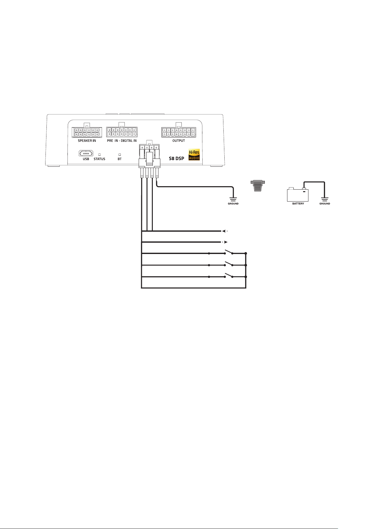
5. CONNECTIONS
The S8 DSP is on when the logo is lit green. It can be turned on/off using the following methods:
1. By connecting the REMOTE IN terminal with a Remote Out signal coming from an after market audio source.
2. Through the Speaker IN (IN 1 - IN 2) input. The ART
TM
, (auto remote TURN-ON) function is activated by connecting
the output (BTL) of an amplified source to the SPEAKER IN 1 - IN 2 input channel. This function can be enabled/
disabled using the S8 DSP software,
(see section 8.2.7.2.1)
.
How to turn the S8 DSP on and off
YELLOW PWR/REM
BLUE REM IN
BLUE/WHITE REM OUT
PINK IN SEL
BLACK MEM GND
BLACK
FUSE
HOLDER
(1A)
from HEAD UNIT
*
not supplied
to Amplifier
REMOTE IN
*
*
*
WHITE MEM SEL 1
WHITE MEM SEL 2
5.1 POWER SUPPLY AND REMOTE TURN ON
5
10
USER’S MANUAL /
5.2 INPUT SIGNALS
5.2.1 PRE IN - CH1/CH6 STEREO ANALOG SIGNAL
5.2.2 DIGITAL IN - S/PDIF DIGITAL INPUT
After market Source
IN 6
IN 5
SUB
REAR
IN 4
IN 3
FRONT
IN 2
IN 1
L
R
L
R
L
R
1234567
PWR/REM
1234567
PWR/REM
S/PDIF OUT
75 Ohm Coax Cable
for digital audio
Not Supplied
Not Supplied
COAX S/PDIF
24 bit 96 kHz max
How to select the PRE IN input
1. By selecting the ANALOG input
(see section. 8.9)
previously set up on (RCA) using the S8 DSP software
(see section 8.2.2)
.
2. By usung the IN SEL terminal
(see section. 4.4)
.
How to select the DIGITAL IN input
1. By selecting the DIGITAL input using the S8 DSP software
(see section. 8.9)
.
2. By usung the IN SEL terminal
(see section. 4.4)
3. With the function Automatic switch to digital input, to be enabled using the S8 DSP software
(see section. 8.2.4)
.
5
11
USER’S MANUAL /
5.2.3 SPEAKER IN - CH1/CH6 (HIGH LEVEL)
123456
PWR/REM
FL
FR
RL
RR
IN 1 +
IN 1 -
IN 2 +
IN 2 -
IN 3 +
IN 3 -
IN 4 +
IN 4 -
IN 5 +
IN 5 -
IN 6 +
IN 6 -
Connect to other
HI-LEVEL OUTPUT
signal if avaiables
After market Source
ART (Automatic Remote Turn-on)
only on IN 1 (+/-) - IN 2 (+/-)
How to select the SPEAKER IN Input
1. By selecting the ANALOG input
(see section 8.9)
previously set on HIGH LEVEL via the S8 DSP software
(see section 8.2.2)
.
2. By using the IN SEL terminal
(see section. 4.4)
.
Remark: the CH1 CH2 channels feature the ART
TM
, (auto remote TURN-ON) function, automatic on/off, through
connection with the source speaker outputs (BTL). This function can be activated via software
(see section 8.2.7.2.1)
.
Remark: the Speaker IN input features USS technology that allows the processor to work with sources equipped with
the “loudspeaker load sensing” circuit.
5
12
USER’S MANUAL /
PWR/REM
BT
STATUS
SPEAKER IN
PRE IN - DIGITAL IN
OUTPUT
Supplied
USB Cable
1
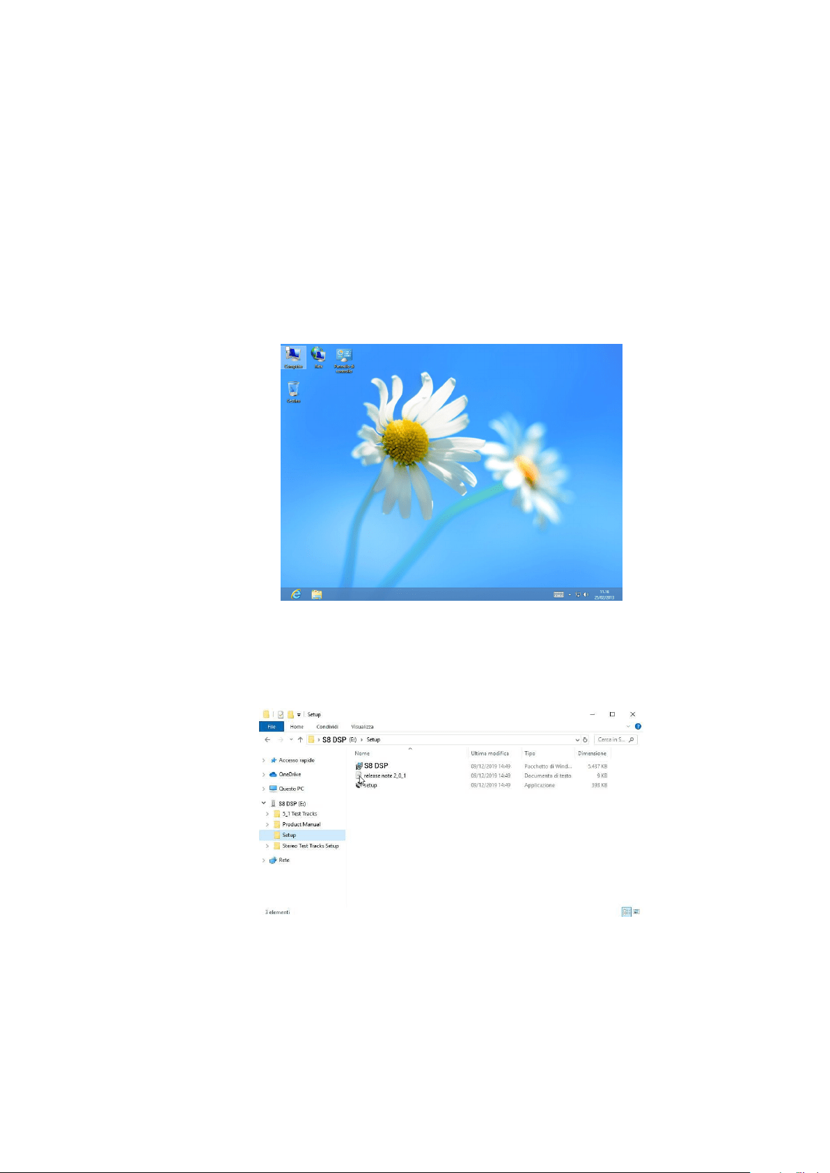
S8 DSP can be connected to PC/MAC:
1. Using the USB cable
2. Using a Bluetooth connection.
5.4 CONNECT S8 DSP TO THE PC/MAC
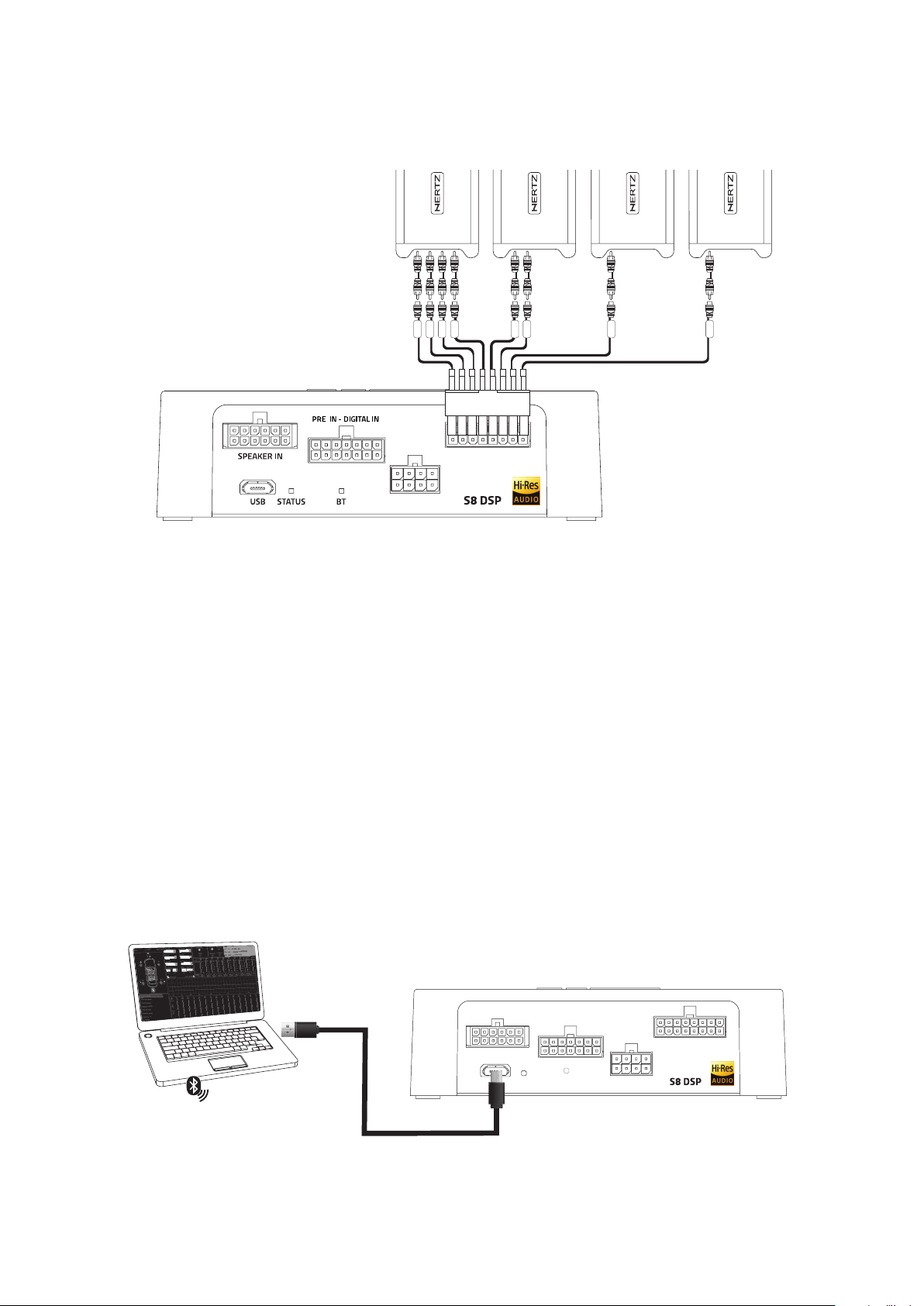
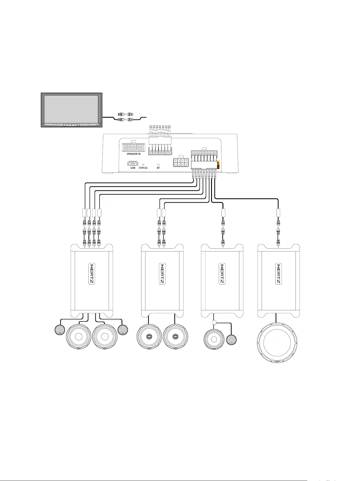
12345678
PWR/REM
CH 5 ÷ CH 6
CH 1 ÷ CH 4
CH 8
CH 7
AMPLIFIER AMPLIFIER AMPLIFIER AMPLIFIER
CH 1
CH 2
CH 3
CH 4
CH 5
CH 6
CH 7
CH 8
5.3 OUTPUT SIGNALS
DEFAULT OUTPUT CONFIGURATION
OUTPUT CH NAME FILTER FILTER TYPE FILTER FREQUENCY/SLOPE
CH1 Front TW Left HI PASS BUTTERWOORTH 3412 Hz @ 12dB
CH2 Front TW Right HI PASS BUTTERWOORTH 3412 Hz @ 12dB
CH3 Front WF Left BAND PASS BUTTERWOORTH 80 Hz @ 12dB / 3412 Hz @ 12dB
CH4 Front WF Right BAND PASS BUTTERWOORTH 80 Hz @ 12dB / 3412 Hz @ 12dB
CH5 Rear Left HI PASS BUTTERWOORTH 80 Hz @ 12dB
CH6 Rear Right HI PASS BUTTERWOORTH 80 Hz @ 12dB
CH7 Center HI PASS BUTTERWOORTH 606 Hz @ 12dB
CH8 Subwoofer BAND PASS BUTTERWOORTH 20 Hz @ 12dB / 80 Hz @ 12dB
5
13
USER’S MANUAL /
6. GUIDE FOR INSTALLING S8 DSP SOFTWARE
6.1 PC WINDOWS
Inside the S8 DSP setup USB device, there are all the files necessary for the setup of the S8 DSP:
• Software S8 DSP (PC Windows)
• This User’s Manual (.pdf)
• Audio test tracks
2.
Windows 10/11: access Computer from the Windows menu.
3. Windows 10/11: select the “S8 DSP setup” USB device and double click on the icon S8 DSP V.X_X_X.
Windows 10/11
Remark: to remove any restrictions on Windows 10/11, operating system, right-click on the setup icon and select the option
“Run as Administrator”. Then select Yes to continue with the installation from the next window “User Account Control”.
6.1.1 INSTALLATION SOFTWARE
1. Insert the “S8 DSP setup” USB setup device in the specific drive on the PC you wish to use.
6
Windows 10/11
14
USER’S MANUAL /
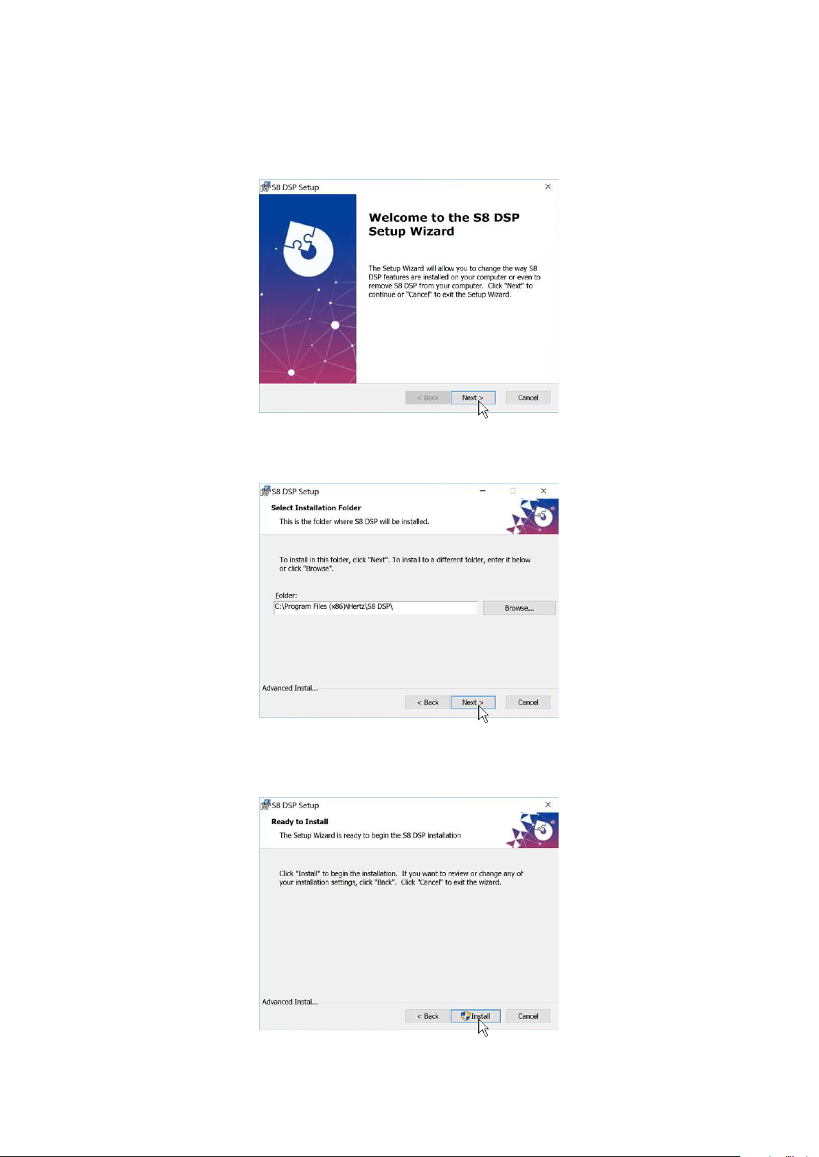
4. Windows 10/11: select Next to go on with the installation, Cancel to interrupt it.
5. Windows 10/11: select Next to go on with the installation, Cancel to interrupt it.
6. Windows 10/11: select Install to go on with the installation, Cancel to interrupt it.
Windows 10/11
Windows 10/11
Windows 10/11
6
15
USER’S MANUAL /
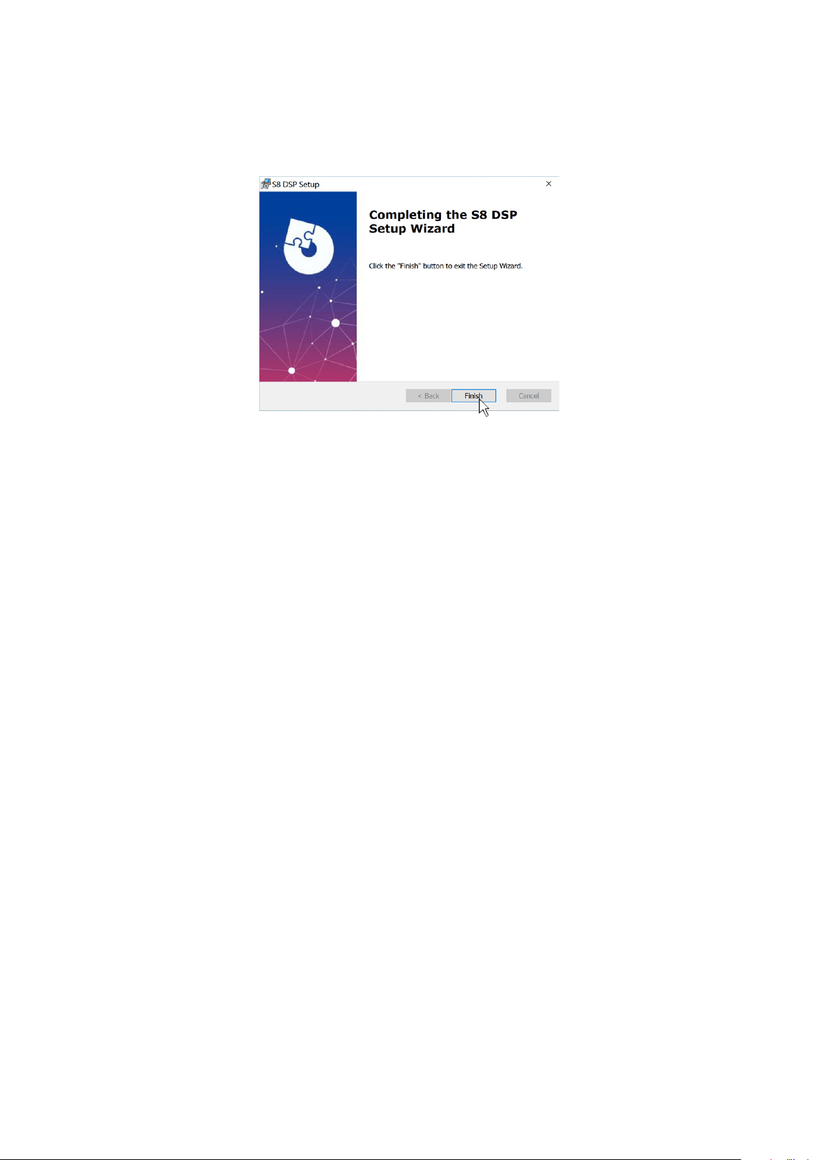
7. Windows 10/11: follow and complete the installation procedure and select Finish at the end of the installation.
6. The PC software is now installed in your system.
Windows 10/11
6.1.2 SOFTWARE UNINSTALL
To uninstall the S8 DSP PC Software for WINDOWS you can follow the below procedure:
Windows 10/11: Start/Settings/App/S8 DSP/Uninstall.
6
16
USER’S MANUAL /
6.2 macOs
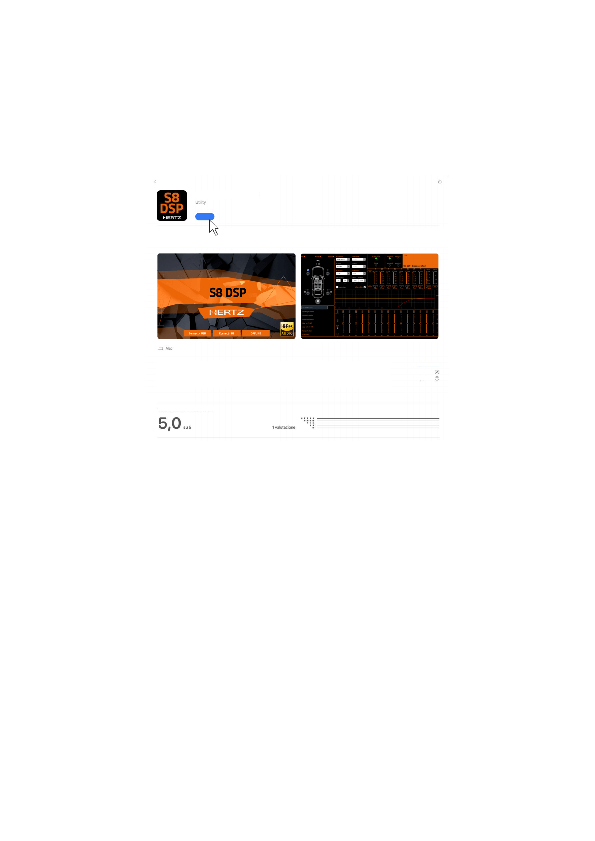
6.2.1 INSTALLATION macOs
1. Search for S8 DSP on the Apple App Store then select “Get” and “Install”.
MacOs
6
GET
S8 DSP Mobile
Elettromedia SRL
Web site
Support
The S8 DSP Mobile App allows the user to manage the S8 DSP signal interface
processor from smartphone /tablet.
Ratings and reviews
17
USER’S MANUAL /
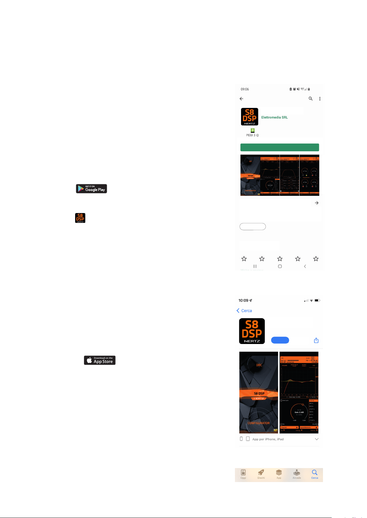
6.3 S8 DSP APP INSTALLATION ON MOBILE DEVICES
2. Scan the QR code printed on the giftbox to access the download
web page:
Installation from Gloogle Play Store
• Select
to access the Google Play Store page
where the S8 DSP Mobile app is listed, then press “Install”.
• Installation from Hertz website.
Select
,to access the product
page, download the latest version of the S8 DSP Mobile app
available, at the end of the download press “Install”.
2. Scan the QR code printed on the giftbox to access the download web
page, select
to access Apple App Store page where the app
S8 DSP Mobile is listed ,then select “Get” and “Install”
6.3.1 ANDROID
1. Search for S8 DSP Mobile on Google Play Store then select “install”.
6.3.2 APPLE iOS
1. Search for S8 DSP Mobile on the Apple App Store then
select “Get” and “Install”.
The S8 DSP Mobile App allows the user to
manage the S8 DSP signal interface processor
from smartphone /tablet.
The S8 DSP Mobile App allows the user to manage
the S8 DSP signal interface processor from
smartphone/tablet.
App info
Evaluate this App
Let others know your opinion.
Tools
Install
6
GET
S8 DSP Mobile
Elettromedia SRL
S8 DSP Mobile

18
USER’S MANUAL /
7. S8 DSP SET UP WITH PC/MAC
To adjust the S8 DSP functions a software is required. The processor needs to be connected to the PC/MC and turned on.
After installing the software, start it by selecting the icon shown on your desktop.
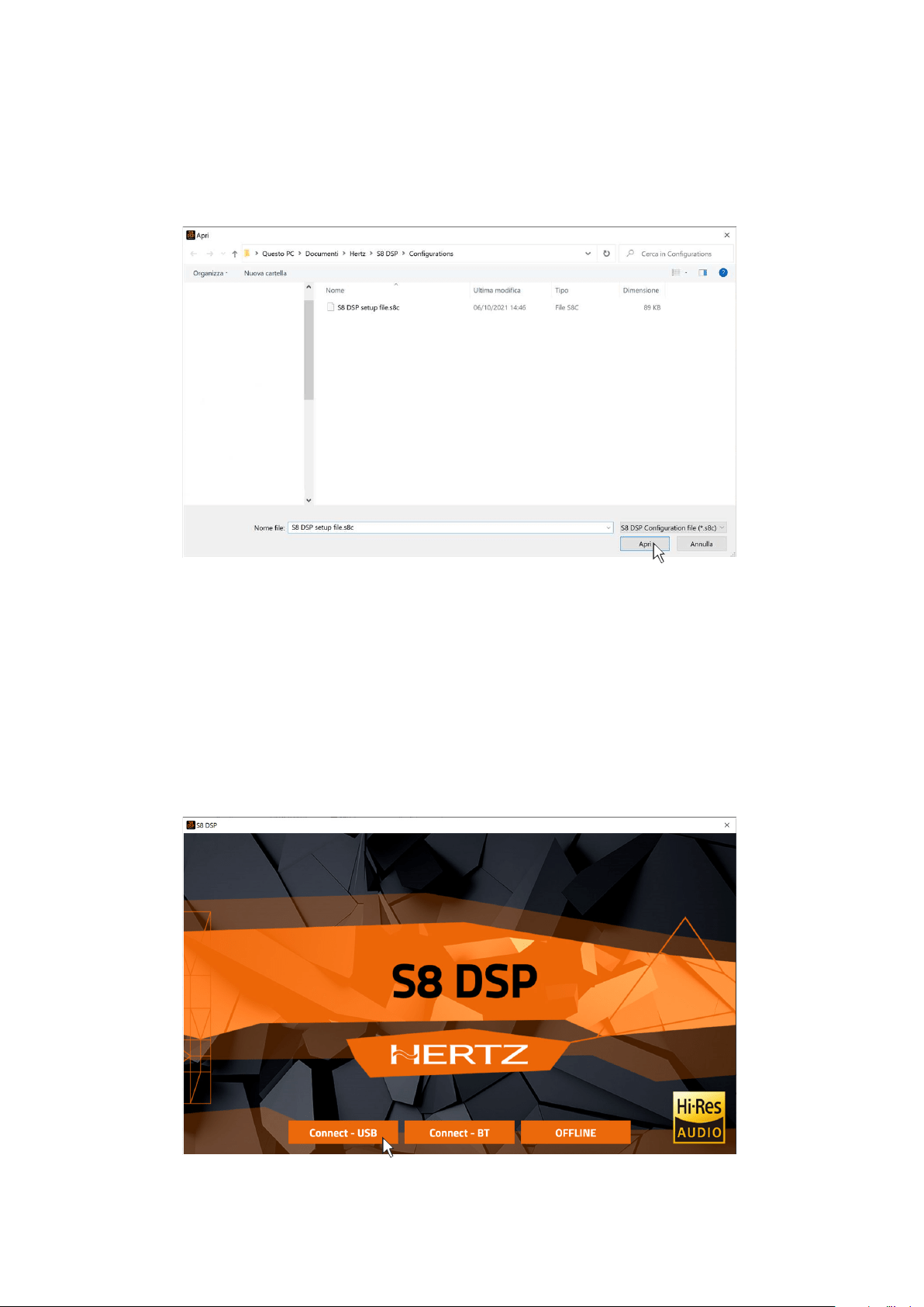
The first window is the startup page where one of the following modes needs to be selected:
- CONNECT - USB, connects the S8 DSP to the PC/MAC via USB;
- CONNECT - BT, allows the connection in bluetooth mode with the PC/MAC (if available);
- OFFLINE, demo mode.
In this case even if the S8 DSP processor is connected to the PC/MAC, it does not interact with the software. The OFFLINE
mode can be used to work on the software to get familiar with the processor multiple functions without connecting
the S8 DSP to the PC/MAC and it is possible to open a saved setup*.s8c or simulate three different configurations:
motorcycle, car, free placement. For the specific functions
(see section 7.5.1)
- Select Create new setup to start the software in demo mode.
- Select Open a saved setup to start the software with a saved setup.
- Select BACK to go back to the start window.
1
2
7.1 OFFLINE MODE
7
19
USER’S MANUAL /
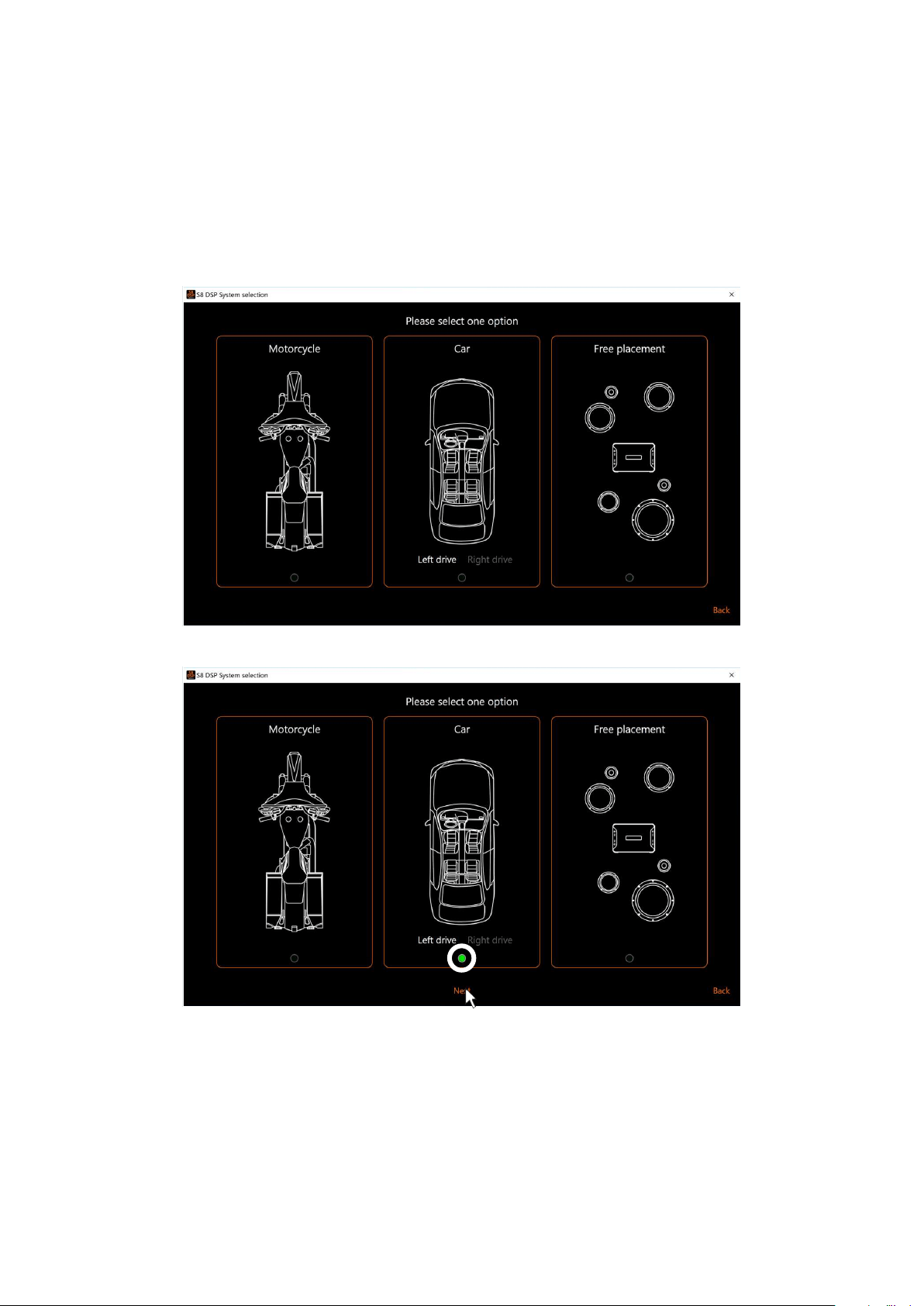
Select the desired option by clicking on the reference image.
- press Next to access the control window
- press Back to go back to the main window
7.1.1. CREATE NEW SETUP
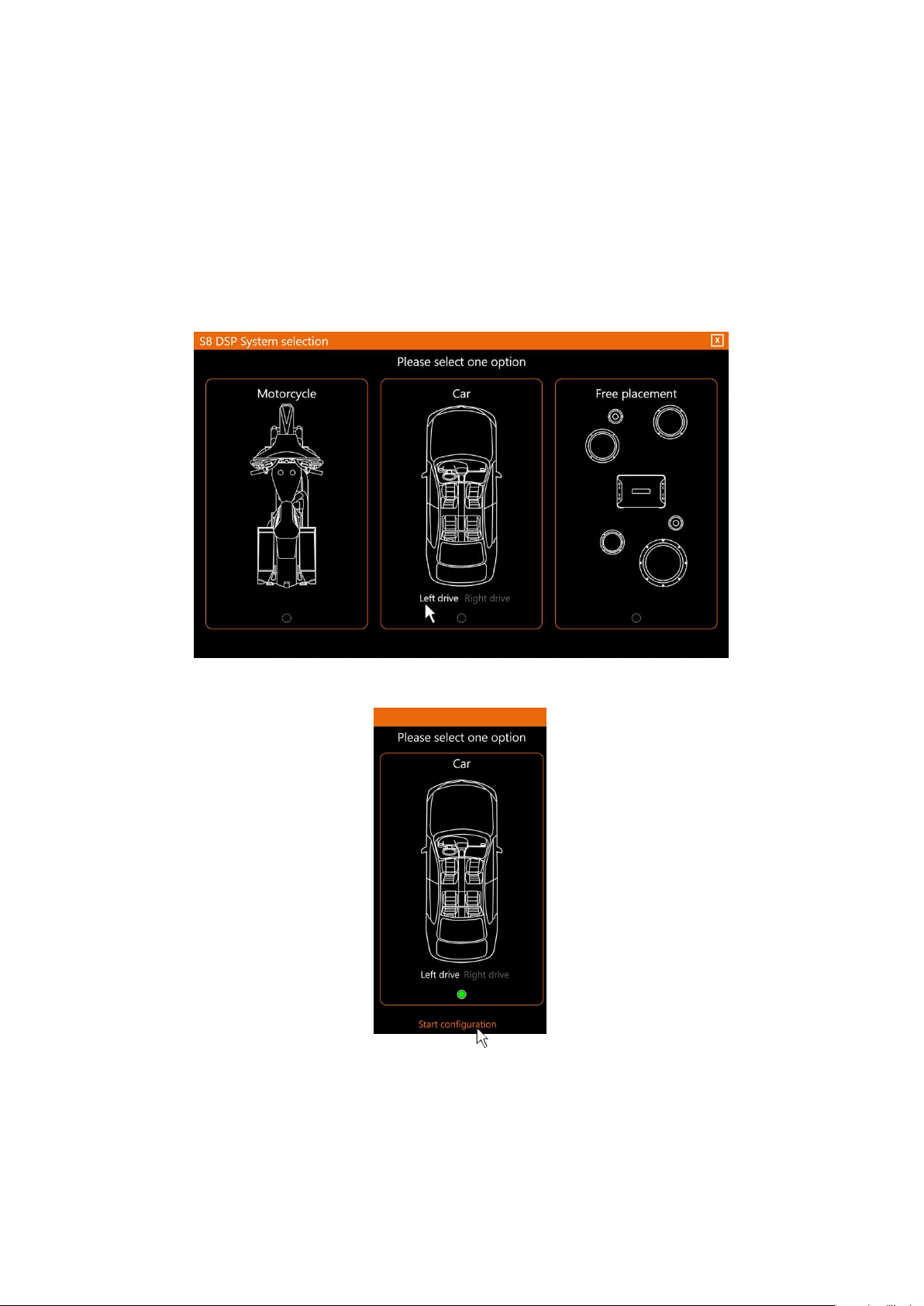
Select Create new setup, to access the System Selection menu where you can select one of the below options:
1. Motorcycle: to simulate a system installed in a motorbike.
2. Car: to simulate a system installed in a car.
3. Free placement: to simulate a system with free placement.
7
20
USER’S MANUAL /
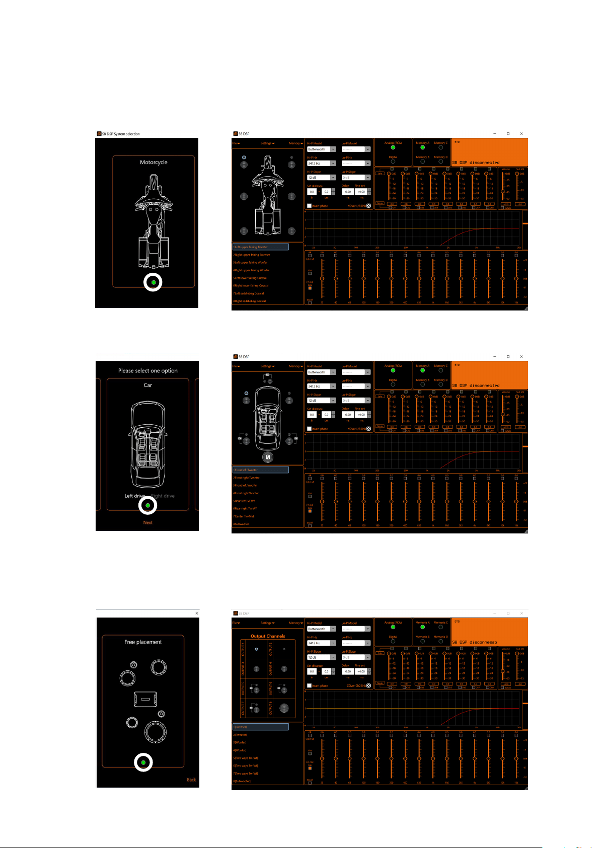
- How does the S8 DSP software look like when starting up in Motorcycle OFFLINE mode.
- How does the S8 DSP software look like when starting up in Car OFFLINE mode.
Remark: in the CAR option the driving side can be set up:
Left drive for left-hand drive car (default).
Right drive for right-hand drive car.
- How does the S8 DSP software look like when starting up in Free placement OFFLINE mode.
7
21
USER’S MANUAL /
To use this function the S8 DSP processor must be turned on and connected to the PC/MAC. The connection
between PC/MAC and S8 DSP can be established via USB cable or Bluetooth.
7.2 CONNECT USB MODE
7.2.1 CONNECTION VIA USB CABLE
1. Start the device (green led status, BT blue led flashing)
2. Connect the USB cable between PC/MAC and S8DSP (light green led status, BT led off)
3. Wait for the PC/MAC to acknowledge and correctly configure the S8 DSP as USB serial device then press
Connect - USB.
7.1.2. OPEN A SAVED SETUP
This function loads the complete configuration of the S8 DSP from a previously saved file (.“S8 DSP setup file.s8c”).
7
22
USER’S MANUAL /
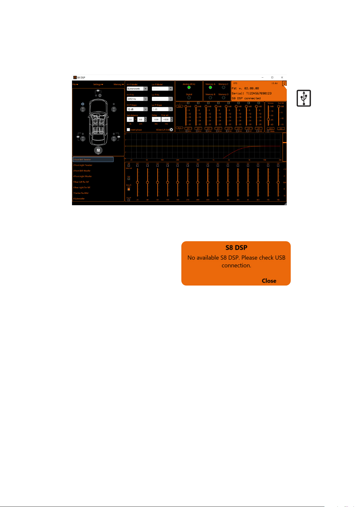
4. The software will start with S8 DSP connected via USB.
Important remark
If S8 DSP is not detected:
- check that S8 DSP is on and correctly
connected to the PC/MAC via USB cable USB
(aqua green led status, BT led off)
- press Close to go back to the main window.
7

23
USER’S MANUAL /
1. Start S8 DSP (green led status, blue BT led flashing).
2. Enable the Bluetooth function on the PC/MAC.
3. Press Connect - BT to open the pop up Select a BT device, and start the search for the S8 DSP processor.
- press Close to stop the search.
- press on the name ie. S8 DSP-XXXX to select the processor.
Remark: in the case of multiple processors available, it will be possible later with the Identify function to check if
the selected S8 DSP is the one desired.
- press Close to stop the operation.
4. Select a BT device: at the end of the search one or more S8 DSP will be detected,“ie.S8 DSP-XXXX”
(XXXX is the identification number of the S8 DSP)
7.3 CONNECT BT MODE
Important remark
In case no processor is detected
at the end of the scan:
- check that the bluetooth interface is enabled on the PC/MAC
- check that the S8 DSP is on and not connected to the PC/MAC via USB
(green led status, BT led flashing)
WARNING: the USB connection to the PC/MAC excludes the possibility
of using the bluetooth connection.
- press Close to stop the operation.
7
24
USER’S MANUAL /
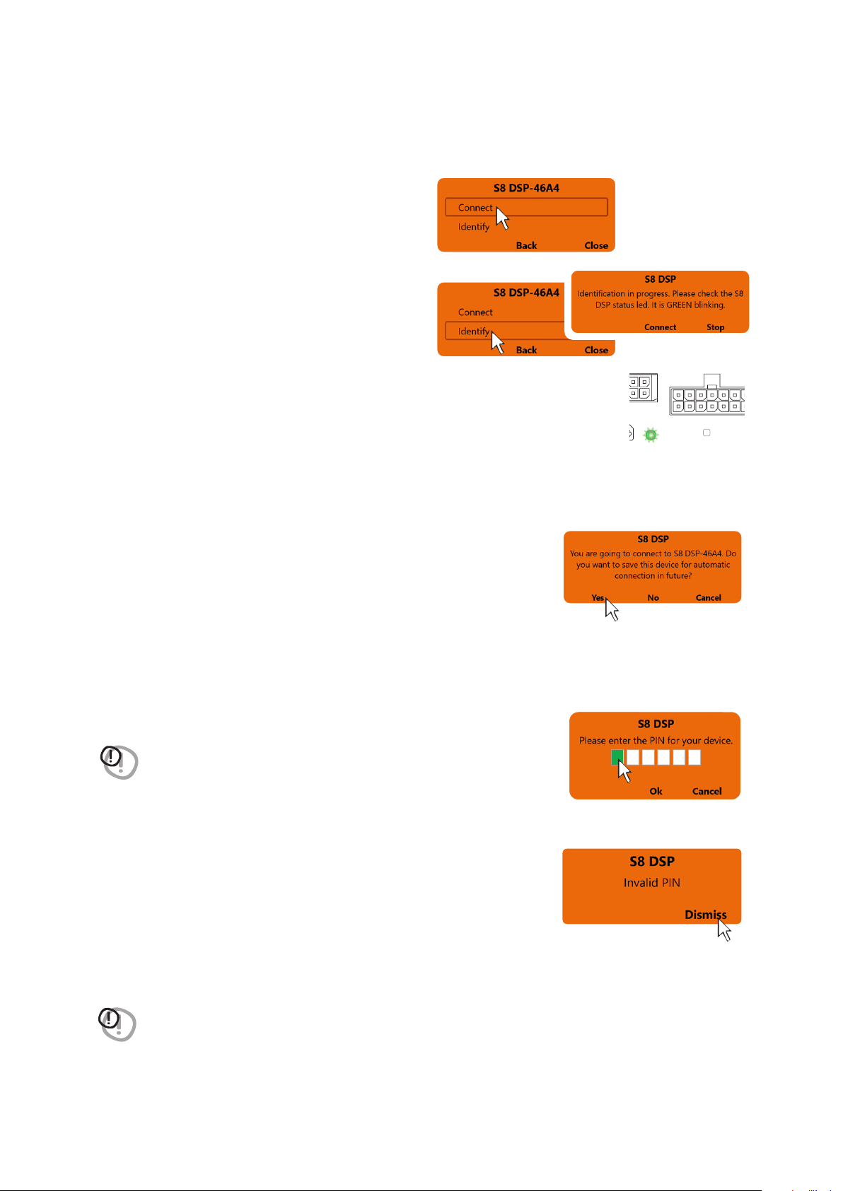
After selecting S8 DSP, a pop up with the processor’s name will appear
- press Connect to go ahead with the S8 DSP
direct connection.
- press Identify to check if the processor you intend
to connect to is the one you want (in the case of
multiple S8 DSP previously detected).
The status LED of the selected S8 DSP will start flashing green.
- press Connect to connect the S8 DSP.
- press Stop to return to the previous screen.
- press Back to go back to the previous window.
- press Close to interrupt the operation.
Remark: when connection for the first time the software will ask whether to
connect automatically to the selected S8 DSP for any future connections,
it will also avoid the PIN request, if enabled
(see section.8.2.8)
Remark: you can later remove the automatic connection of the S8 DSP with the function “Bluetooth>Forget”
(see section.8.1.6.3)
.
- press Yes to connect S8 DSP automatically in the future and access the control software.
- press No not to connect S8 DSP automatically in the future and access the control software .
- press Cancel to cancel the operation.
BT
STATUS
SPEAKER IN
PRE IN - DIGITAL IN
- press OK after entering the PIN to access the control software.
- press Cancel to cancel the operation.
Invalid PIN: if the PIN entered is incorrect, the bluetooth connection operation
must be repeated from the beginning.
- press Dismiss to go back to the main window.
WARNING: If the Bluetooth PIN has been activated previously
(see section 8.2.8)
click on
the first white box on the left to enter the numbers with the PC/MAC
keyboard.
WARNING: if the pin is not available, it is still possible to connect the S8 DSP
to the software via the USB connection.
7
25
USER’S MANUAL /
7.4 S8 DSP DEFAULT SETUP
By default, the S8 DSP is configured as shown below:
7.4.2 OUTPUTS
Output (Pre Out):
- Ch1-Ch2: Front Tw (L/R)
- Ch3-Ch4: Front Wf (L/R)
- CH5-CH6: Rear Tw/Wf (L/R)
- CH7: Center Tw/Mid
- CH8: Subwoofer
Subwoofer is the sum of the 2 input channels.
7.4.1 INPUTS
Pre In
- CH1-CH2
FRONT
IN 1
IN 2
L
R
12345678
1234567
PWR/REM
CH 1
CH 2
CH 3
CH 4
CH 5
CH 6
CH 5
CH 6
After market Source
CH 1 ÷ CH 4
AMPLIFIER
CH 8
AMPLIFIER
CH 5 ÷ CH 6
AMPLIFIER
CH 7
AMPLIFIER
TW FL
WF FL Coax RL
TW FR
WF FR Coax RR Centre
Subwoofer
7
26
USER’S MANUAL /
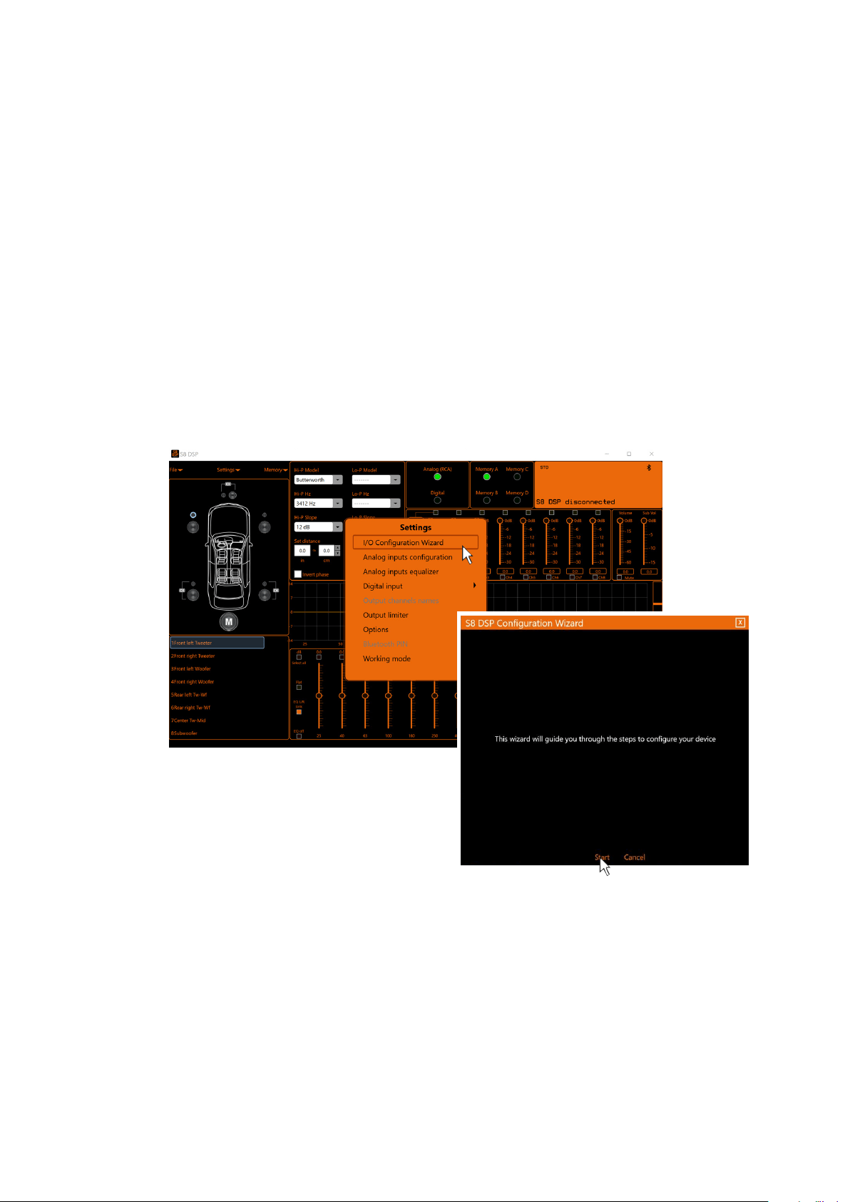
7.5 I/O CONFIGURATION WIZARD
Before starting the “I/O Configuration Wizard” connect the source loudspeakers’ outputs to the SPEAKER IN input
(see section 5.2.3)
or the source PRE OUT outputs to the S8 DSP PRE IN input
(see section 5.2.1)
.
At this point it is necessary to know in advance the system to be implemented, since later, to change these
selections, you will have to run the guided procedure
In particular, the wizard will request:
- What system will S8 DSP be installed on.
- Which speakers make up the system (
E.g.: 3-way Front or Sub stereo or 2-way Rear etc.
).
- If there are passive crossovers that handle groups of speakers (
E.g.: 3-way system with active mid-bass
).
- Which type of main inputs will be used, if high level or low level.
This selection will not prevent the use of digital sources.
- Which input/s will be assigned to each output, it is possible to configure an output system with stereo input,
customized, or with reconstruction of the input signal.
- Click on the Settings menu and select I/O Configuration Wizard.
- Press Start to start the Configuration Wizard.
- Press Cancel to exit the Configuration Wizard.
7
27
USER’S MANUAL /
7.5.1. SYSTEM SELECTION
It is possible to configure S8 DSP in 3 different types of system:
- Motorcycle: this option provides the ability to configure the S8 DSP for a system installed on a motorcycle.
- Car: this option provides the ability to configure S8 DSP for a system installed in a car.
Remark: in the CAR system the driving side can be selected:
Left drive: left-hand drive car(default setting)
Right drive: right-hand drive car.
- Free placement: this option allows you to configure the S8 DSP for a free placement system.
- Press Start Configuration to go on with the configuration.
- Select the desired option by clicking on the reference image.
7
28
USER’S MANUAL /
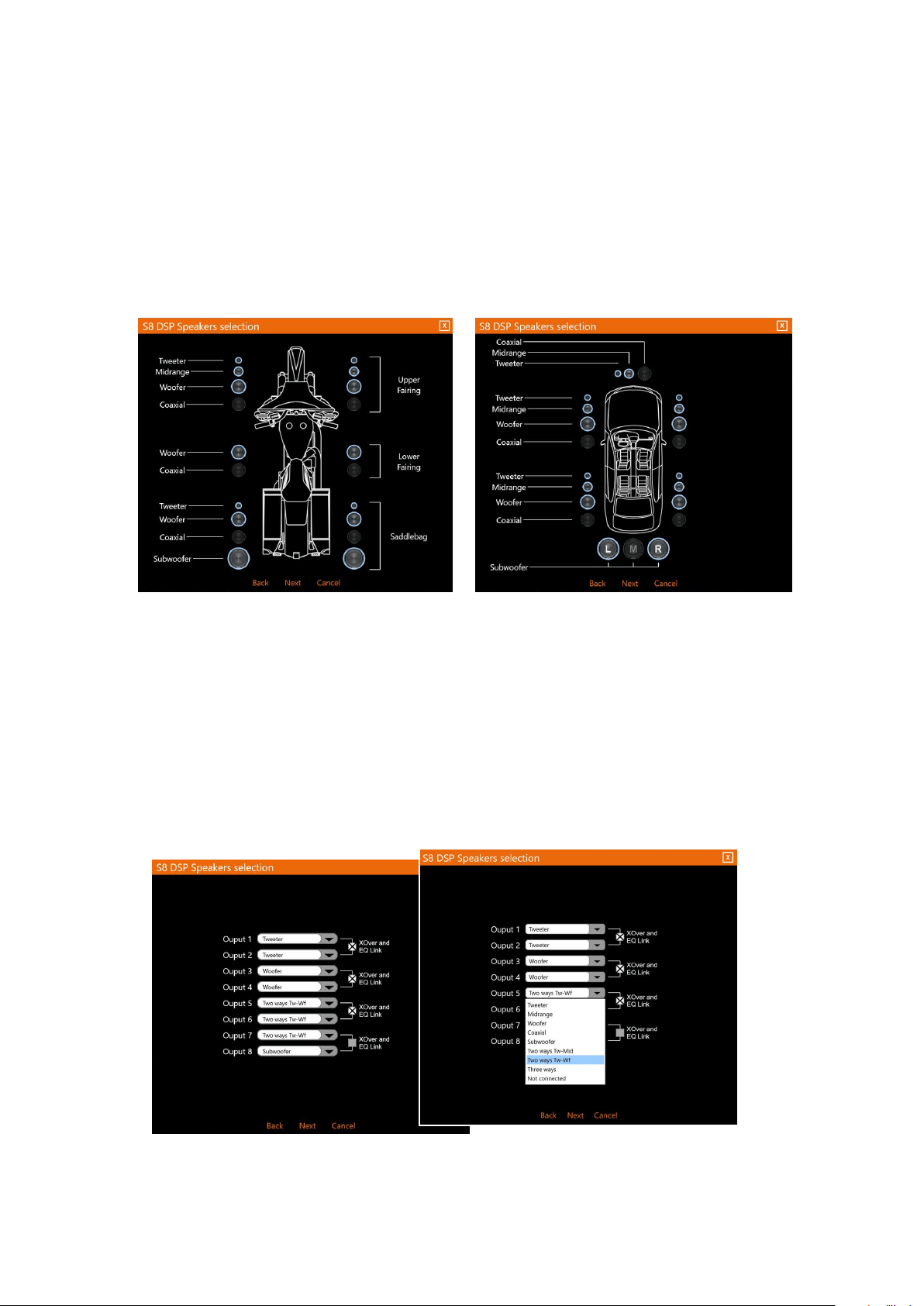
7.5.2. SPEAKER SELECTION
Motorcycle / CAR option
In Motorcycle or Car mode, through the appropriate screen, you can select the speakers in your system, to
be activated or deactivated by clicking on them. The software assumes that if you select the left tweeter,
midrange, woofer or coaxial, the right ones will also be activated automatically. This choice will affect the type
of dedicated crossover.
E.g.: if only the woofers have been activated for the rear system, only a low-pass or band-pass filter will be
available within the software.
How Speaker Selection looks like in Motorcycle mode How Speaker Selection looks like in Car mode
- press Next to continue with the configuration.
- press Back to go back to the previous window.
- press Cancel to cancel the operation.
Opzione Free placement
In Free Placement mode, you can directly choose the speaker or speaker system
(
E.g. 2-way tweeter / woofer or 3-way tweeter/midrange/woofer
)
, for each output
.
This selection will affect the type of dedicated crossover, (
E.g.: if output 1 is configured as a tweeter, only a
high-pass filter will be available within the software, if output 2 is configured as a woofer only a low-pass or
band-pass filter
).
If you select the same type of loudspeaker or loudspeaker system for one of the 4 pairs of outputs, the
software will automatically activate the “Xover and EQ Link” function
(see section 8.6.1 - 8.7.7)
.
This function can be deactivated by clicking on it.
How Speaker Selection in Free placement looks like
- press Next to continue with the configuration.
- press Back to go back to the previous window.
- press Cancel to cancel the operation.
7
29
USER’S MANUAL /
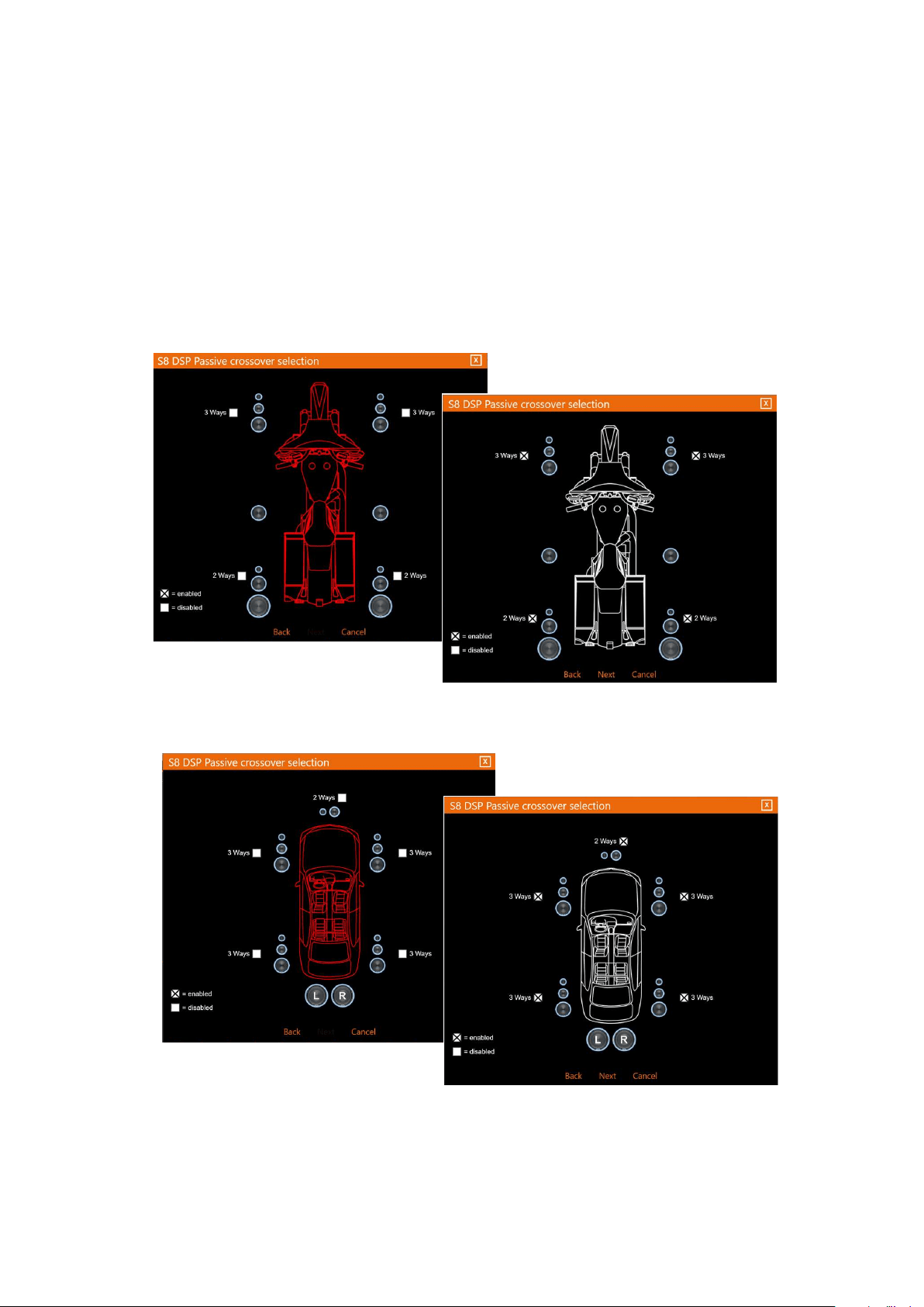
How Passive crossover
Selection looks like in
Motorcycle mode .
How Passive crossover
Selection looks like in Car
mode
7.5.3. PASSIVE CROSSOVER SELECTION - OUTPUT CHANNELS ASSIGNMENT / OUTPUT CHANNELS NAME
- Passive crossover selection:
In Motorcycle or Car mode it is possible to indicate the presence of passive crossovers by enabling
the 2Ways / 3Ways options.
E.g.: the front 3-way can be operated as:
- multi-amplified (6 output channels would be needed);
- passive mid-highs + separately amplified woofer (4 output channels would be needed);
- 3-way passive (2 output channels would be needed).
Remark: During the selection, the software will automatically signal the return to the limit of the 8 output
channels, making the vehicle image turn from red to white and the Next button will appear.
- press Next to continue with the configuration.
- press Back to go back to the previous window.
- press Cancel to cancel the operation.
7
30
USER’S MANUAL /
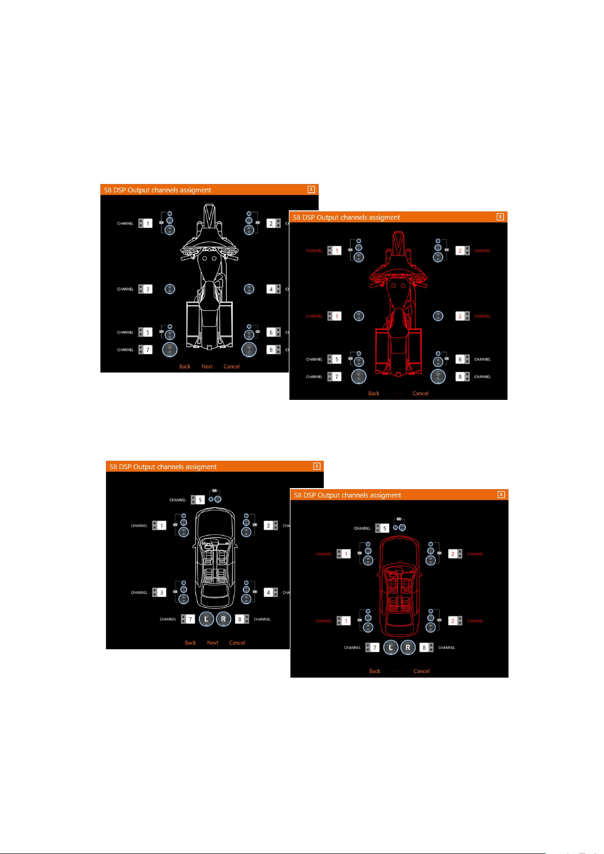
- Output channels assignmet
In Motorcycle or Car mode it is possible to change the order in which the outputs of the S8 DSP have been
automatically assigned by the software. The software will report if in the event of an error the same output
will be assigned to multiple speakers, in this case the vehicle image will turn from white to red and the NEXT
button will disappear from the screen, until the correct assignment of the outputs.
How Passive crossover
Selection looks like in
Motorcycle mode
How Passive crossover
Selection looks like in
Car mode
- press Next to continue with the configuration.
- press Back to go back to the previous window.
- press Cancel to cancel the operation.
7
31
USER’S MANUAL /
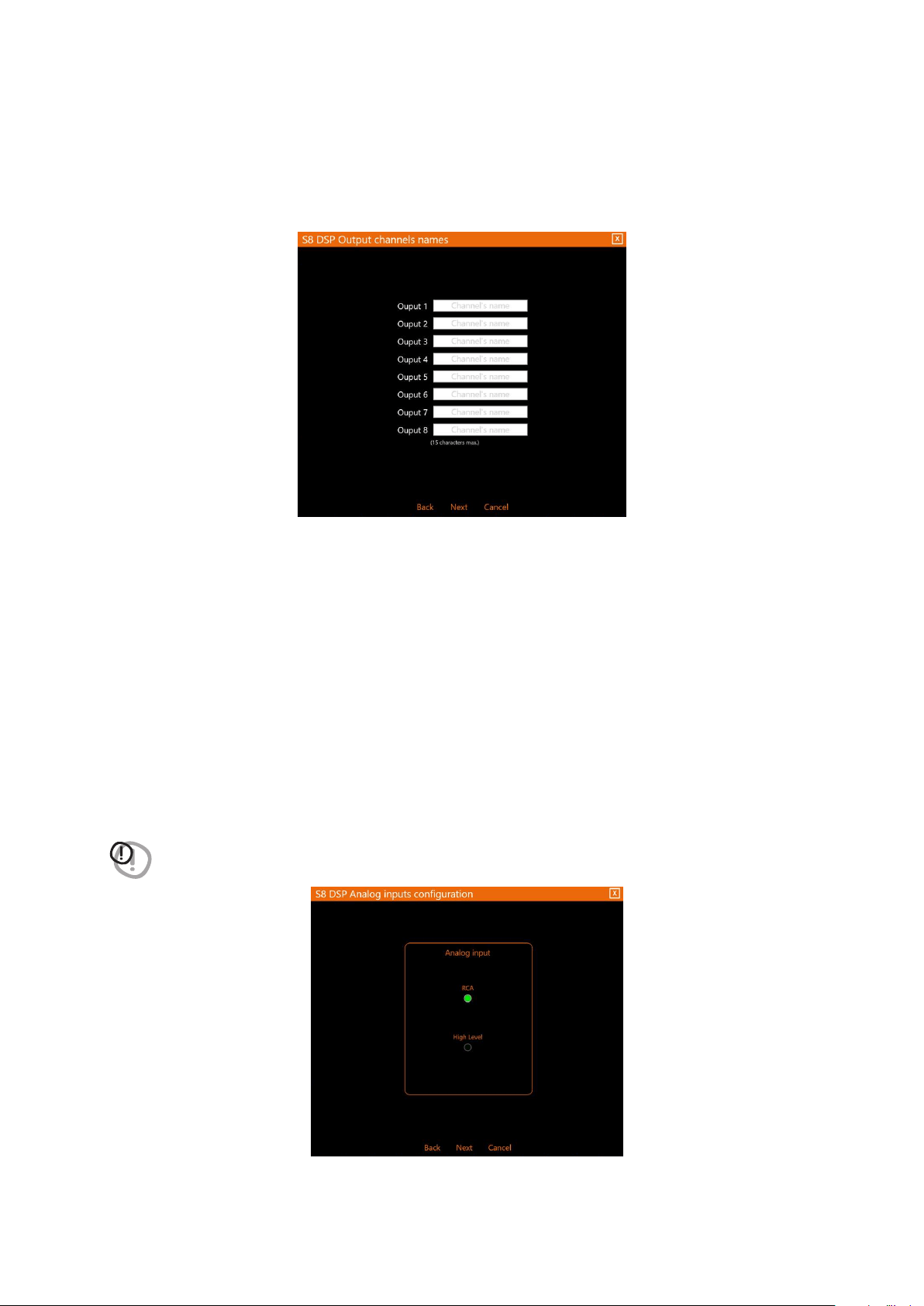
- Output channels names
In Free Placement mode it is possible to rename each output channel with a maximum of 15 characters, so as
to facilitate their recognition while using the software.
- press Next to continue with the configuration.
- press Back to go back to the previous window.
- press Cancel to cancel the operation.
7.5.4. ANALOG INPUTS CONFIGURATIONS
It is possible to select the type of analog input used: RCA (PRE IN) or High Level (SPEAKER IN)
This selection will set the sensitivity scale displayed in the Sensitivity window
(see section 7.5.6- 8.2.2)
- RCA the sensitivity scale will be set with values from 0.8 to 6 Vrms
- Hi level the sensitivity scale will be set with values from 2.5 to 21Vrms
WARNING: the selection of the type of RCA/Hi Level input will affect the type of sensitivity scale displayed in the
software, so it is important to make sure that there is a correspondence with the input used.
- press Next to continue with the configuration.
- press Back to go back to the previous window.
- press Cancel to cancel the operation.
7
32
USER’S MANUAL /
7
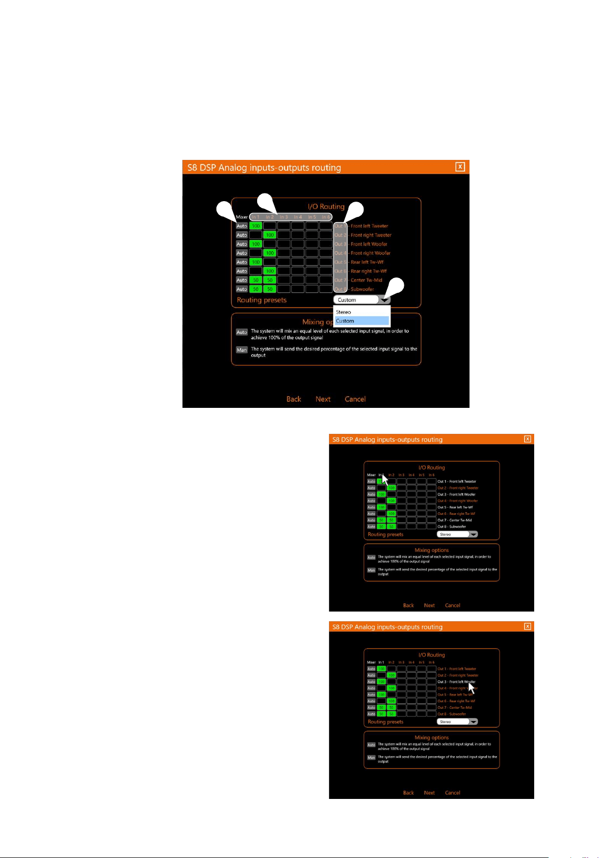
7.5.5 ANALOG INPUTS-OUTPUTS ROUTING
It is a mixer in which it is possible to view and / or modify the assignment of the input signals on each output
channel (this means that an input channel can be sent to one or more output channels and vice versa), and adjust
the mixing percentages.
3
1
4
In1-In2-In3-In4-In5-In6
are the S8 DSP input channels
Remark: hovering the mouse cursor over an input channel,
the associated output channels will be highlighted
The mixer is structured as a matrix:
OUT1-OUT2-OUT3-OUT4-OUT5-OUT6-OUT7-OUT8
are the S8 DSP output channels.
Remark: hovering the mouse cursor over an output
channel, the associated input channels will be
highlighted.
2
1
2
33
USER’S MANUAL /
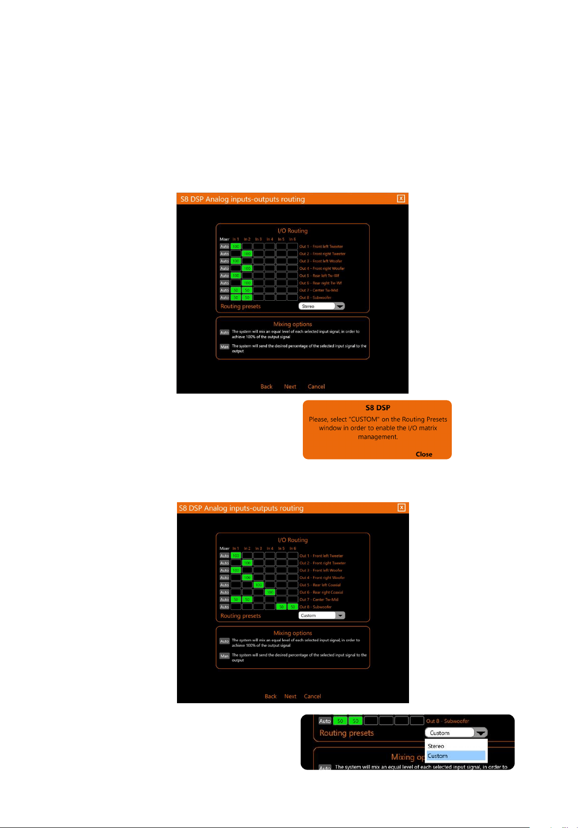
Remark: when operating on the mixer in Stereo
mode, a pop up will appear with the warning to
use the Custom option to customize the
assignment of the inputs to the outputs.
Remark: it is possible to switch from the
Routing Preset Stereo mode (default), to the
Routing Preset Custom mode by selecting them
using the appropriate drop-down menu.
CUSTOM allows the user to operate on the mixer.
It is possible to use all available inputs (IN1 / IN6) to configure the system.
The input is assigned to the output when the box turns green and the mixing percentage will be shown inside.
7
ROUTING/PRESET: it is possible to assign inputs to outputs in two ways (STEREO) or (CUSTOM).
STEREO (default) does not allow to operate on the mixer.
The system will be configured using the inputs In1 and In2, the assignment to the outputs is automatic and
cannot be changed.
Input In1 will be assigned to the Left outputs;
The In2 input will be assigned to the Right outputs; while the mono outputs (
E.g. subwoofer or center
) will be
associated with both inputs In1-In2.
3
34
USER’S MANUAL /
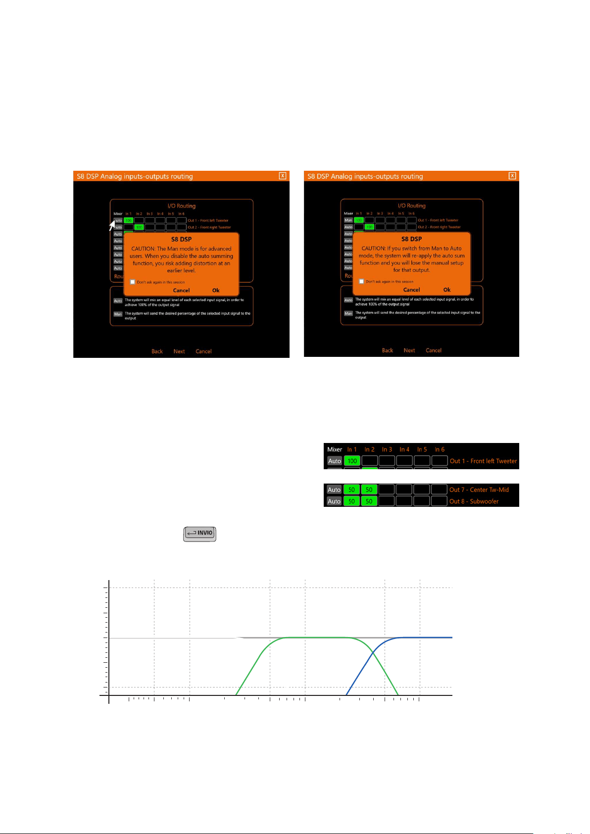
MIXER:
It is possible to assign the mixing percentages of the inputs in two ways: (Auto/Man).
It is possible to switch from the Mixer Auto mode (default), to the Mixer Man mode and vice versa clicking on
the
Auto or Man keys, upon clicking a warning pop up will appear on the screen.
Auto, (Default) The software will calculate, based on the selected inputs, a percentage of equal value in order to
reach 100% of the signal at the assigned output.
Man, it is possible to manually operate on the mixing percentages, assigning the desired value to each input
and confirming it with
E.g. if you want to reconstruct a full range signal from a source with filtered outputs, each input can be set to
100% in order to obtain a Full range output signal without distortion.
E.g. If only one input is associated with an output, the
software will set it to 100% (fig 1), while if several inputs
are associated with a mono output (Eg. Subwoofer or
Center), the software will set them in equal percentage
(50% / 50%) so that their sum is 100%. (fig 2).
Fig. 1
Fig. 2
%
100 1K 10K
0
100
- select “Don’t ask again in this session” to stop showing this pop up in this work session.
- press OK to switch mode.
- press Cancel to cancel the operation.
Switching from Mixer Auto mode to Mixer Man mode
IN 2
OUT
IN 3IN 1
7
4
35
USER’S MANUAL /
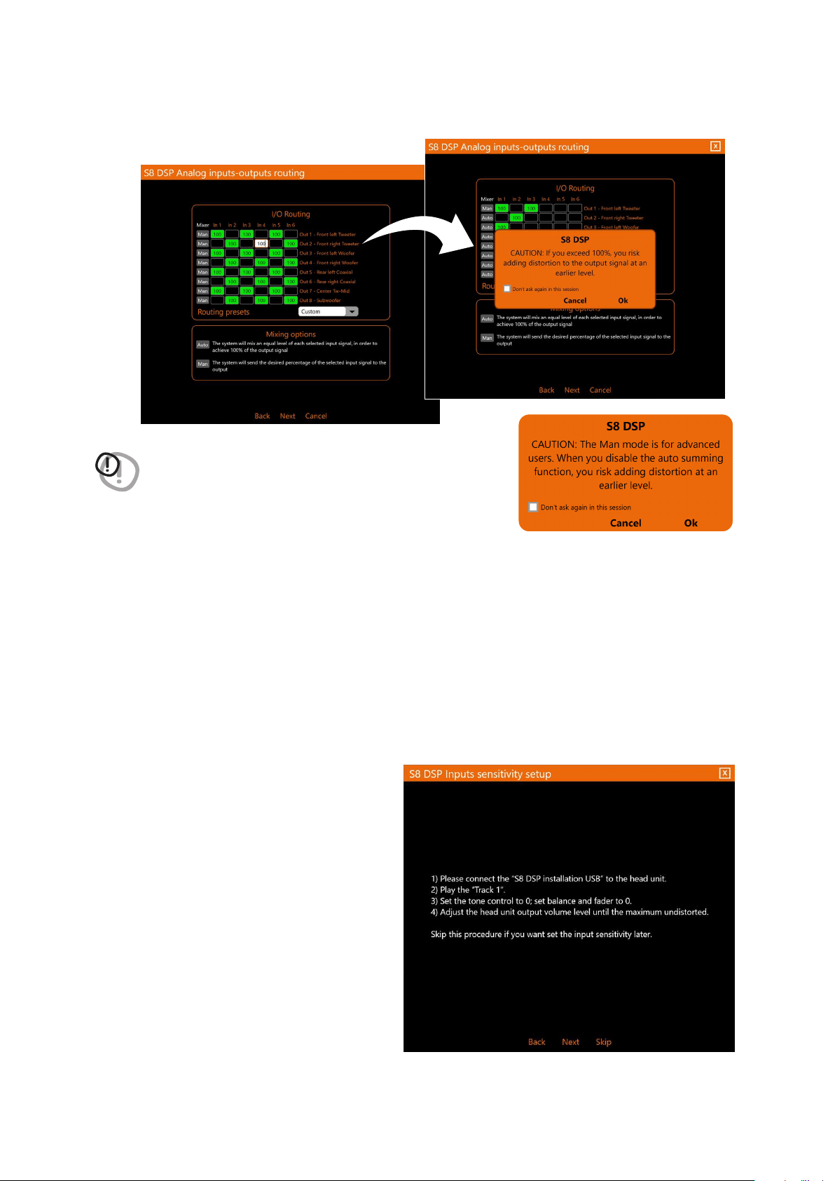
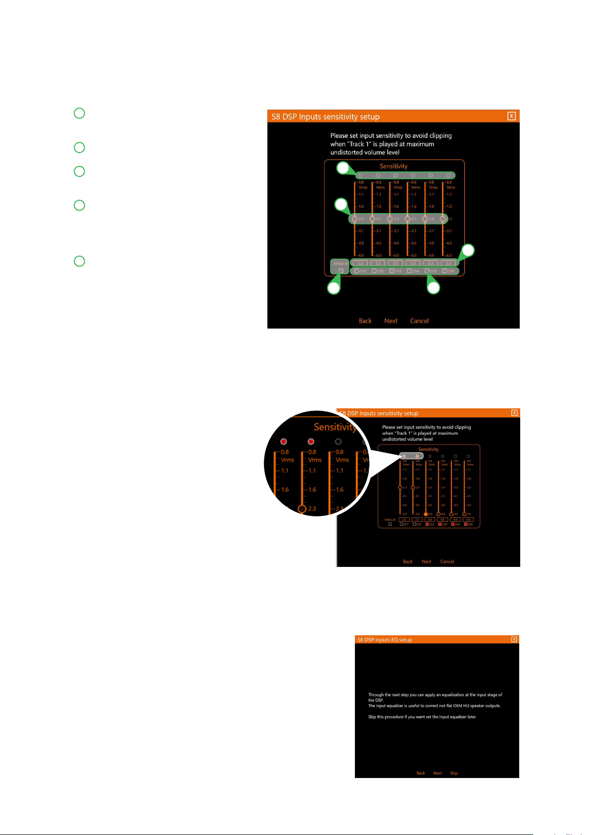
7.5.6 INPUTS SENSITIVITY SETUP
The calibration of the input levels is essential to adapt the sensitivity of the S8 DSP to the signal coming
from the source, the sensitivity scale will vary according to the selection made previously in the Analog inputs
configurations menu:
(see section 7.5.4 - 8.2.2)
.
- RCA the sensitivity scale will be set with values from 0.8 to 6 Vrms.
- Hi level the sensitivity scale will be set with values from 2.5 to 21 Vrms .
Before proceeding with the calibration,
follow the instructions below:
- insert the supplied USB into the source
- play track 1
- set all tone controls to 0
- set balance and fader to 0
- set the volume of the source to
the maximum undistorted level
Remarks: if you do not have the opportunity to try the
source first, bring the volume adjustment to about
80% of its maximum excursion. If the output level
of the source is positioned too low, the S8 DSP may
produce a background noise (puff).
If during playback the S8 DSP should exhibit such
noise, the calibration should be repeated
- Press BACK to go back to the previous window.
- Press NEXT to perform the inputs calibration.
- Press SKIP to skip the inputs calibration.
WARNING: in the case of the mixer configuration in MAN mode, the software
removes the control on the maximum value of the sum of the input
signals. Therefore, when the 100% threshold is exceeded (risk of
output distortion) a pop-up will appear to confirm the operation.
- press OK to switch mode.
- press Cancel to cancel the operation.
- select “Don’t ask again in this session” to stop showing this pop up in this work session.
After setting up the mixer
- press Next to continue with the configuration.
- press Back to go back to the previous window.
- press Cancel to cancel the operation.
7
36
USER’S MANUAL /
How Input Sensitivity Setup looks like in RCA mode
Input clipping indicator. When the LED lights up,
it signals the presence of clipping on the
selected input.
By operating on one of the sliders, it will be
possible to adjust the sensitivity of each input.
Indicator of the sensitivity level of each
individual input channel, referred to the
position of the slider indicated above.
By clicking on the buttons it will be possible
to select a group of S8 DSP inputs for which
it will be possible to adjust the sensitivity
levels at the same time. Click the button
again to disable the function.
Select all: by clicking on the “Select all”
button it will be possible to adjust all the
sensitivity levels of the inputs of the S8 DSP
simultaneously. By clicking again on the
“Select All” button it will be possible to
disable the function.
Input sensitivity level calibration:
• With track 1 in progress, gradually decrease or increase the sensitivity of the first input used until the LED
turns on or flashes red, then you have to go back one step (the LED turns off)
• Carry out the same operation for the other inputs used.
- press Next to continue with the configuration.
- press Back to go back to the previous window.
- press Cancel to cancel the operation
.
3
4
5
2
1
7.5.7 INPUTS EQ SETUP (ANALOG INPUTS EQUALIZER)
The S8 DSP software provides an input equalizer, which can be managed by a maximum of 7 parametric equalization
bands per channel, this operation is useful for correcting the outputs of OEM HU sources when they are equalized.
-
Press Back to go back to the previous window.
-
Press NEXT to access the inputs equalization.
-
Press SKIP to skip the inputs equalization procedure.
7
3
4
5
2
1

37
USER’S MANUAL /
Volume: by operating on the “Volume” slider, you can make adjustments to the overall system output level
(-60 ÷ 0 dB).
Mute: by clicking on the “Mute” button it is possible to mute the output channels.
Click the “Mute” button again to disable the function.
Input Channel: by clicking on the drop-down menu, you can select the input channel you intend to equalize.
In order to display the set equalization curve more clearly, using the slider it is possible to increase or
decrease the vertical scale (dB).
This part of the screen indicates the frequency (HZ) of each intervention pole of the equalization referred to
the position of the “Fo” slider.
By clicking on the buttons it is possible to select a group of equalization poles to which the Gain levels can be
adjusted at the same time. By clicking on the button again, the function will be disabled.
Select all: by clicking on the “Select all” button it will be possible to adjust all the Gain levels of the equalization
poles at the same time. By clicking on the “Select all” button again, the function will be disabled.
Flat: by clicking on the Flat button, the Gains of all poles will be returned to the 0 dB position.
EQ Link: when active, it applies the equalization curve of the left channel to the right channel or vice versa.
EQ off: by clicking on the EQ off button, the equalizer on the selected channel or 2 channels (EQ Link active)
selected is deactivated to check the effect without losing the settings. By clicking on the “EQ off” button again,
the function will be disabled.
G (dB): by operating on the “G” slider, it will be possible to make adjustments to the gain of the selected pole
(Gmin +12dB ÷ Gmax -12dB).
Fo (Hz): by operating on the “Fo” slider, it will be possible to make adjustments to the frequency of the selected pole.
Q: by operating on the “Q” slider, it will be possible to make adjustments to the “Q” quality factor of the
selected pole (Q: 1 ÷ 15 step min 0.1).
This part of the screen displays the values of G (dB), Fo (Hz), Q set for each equalization pole.
- Press BACK to go back to the previous window.
- Press NEXT to perform the inputs equalization.
- Press SKIP to skip the inputs equalization.
Remarks: A finer adjustment of these parameters can also be made using the keyboard of your PC / MAC
TAB key
: allows you to select the slider, “G” “Fo” and “Q” for each equalization pole.
The successful selection is visible through the orange color of the adjustment slider.
Keys and : allow fine adjustment of the selected slider.
WARNING: if you proceed with the inputs equalization, S8 DSP will enable the audio outputs, the general volume will
be set by default to -42dB to avoid damaging the speakers when starting calibration.
11 12 13
3
4
14
5
6
2
7
8
9
10
1
1
9
5
13
3
11
7
2
10
6
14
4
12
8
7
38
USER’S MANUAL /
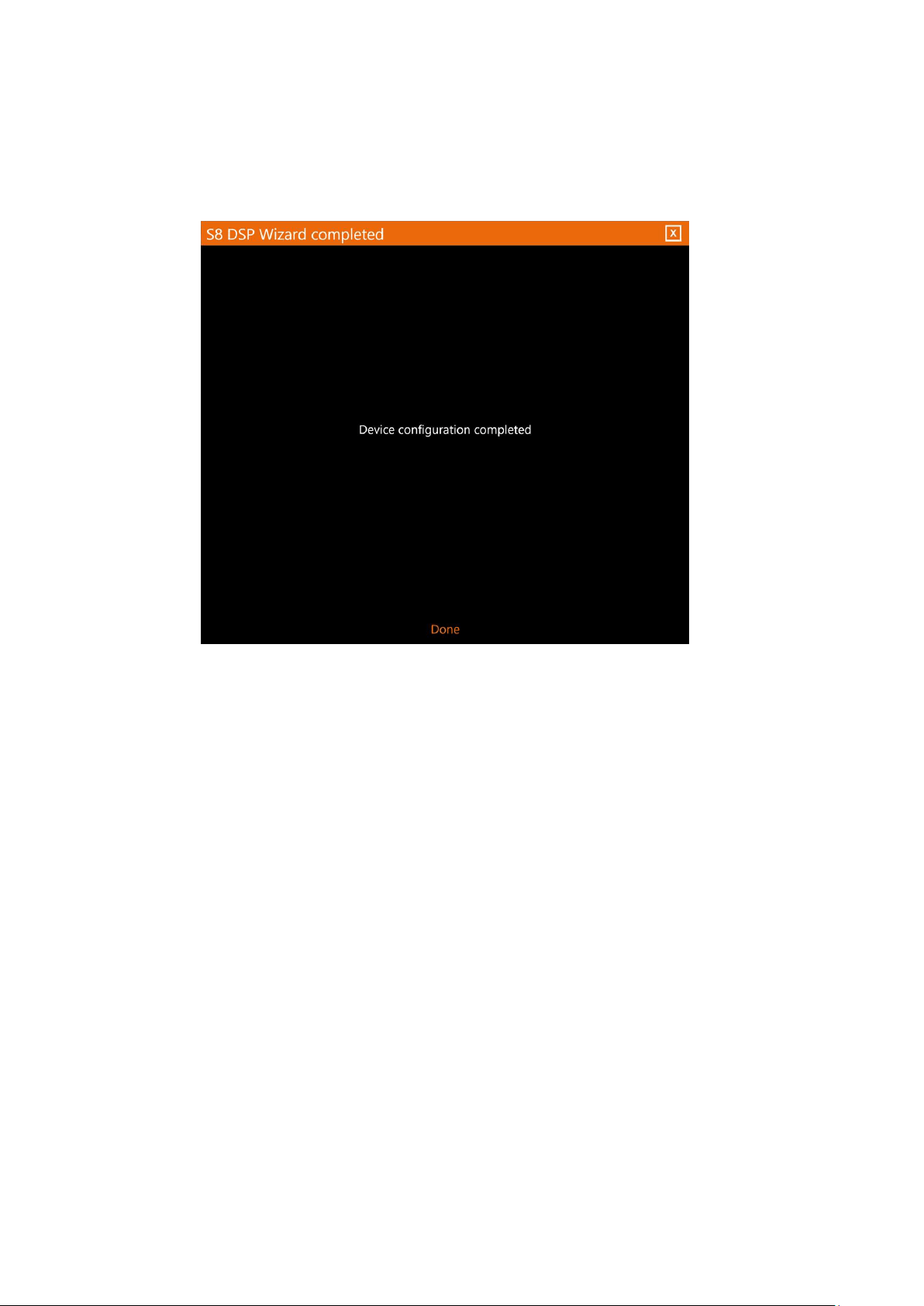
- Press DONE.
7.5.8 WIZARD COMPLETED
System setup is complete.
7
39
USER’S MANUAL /
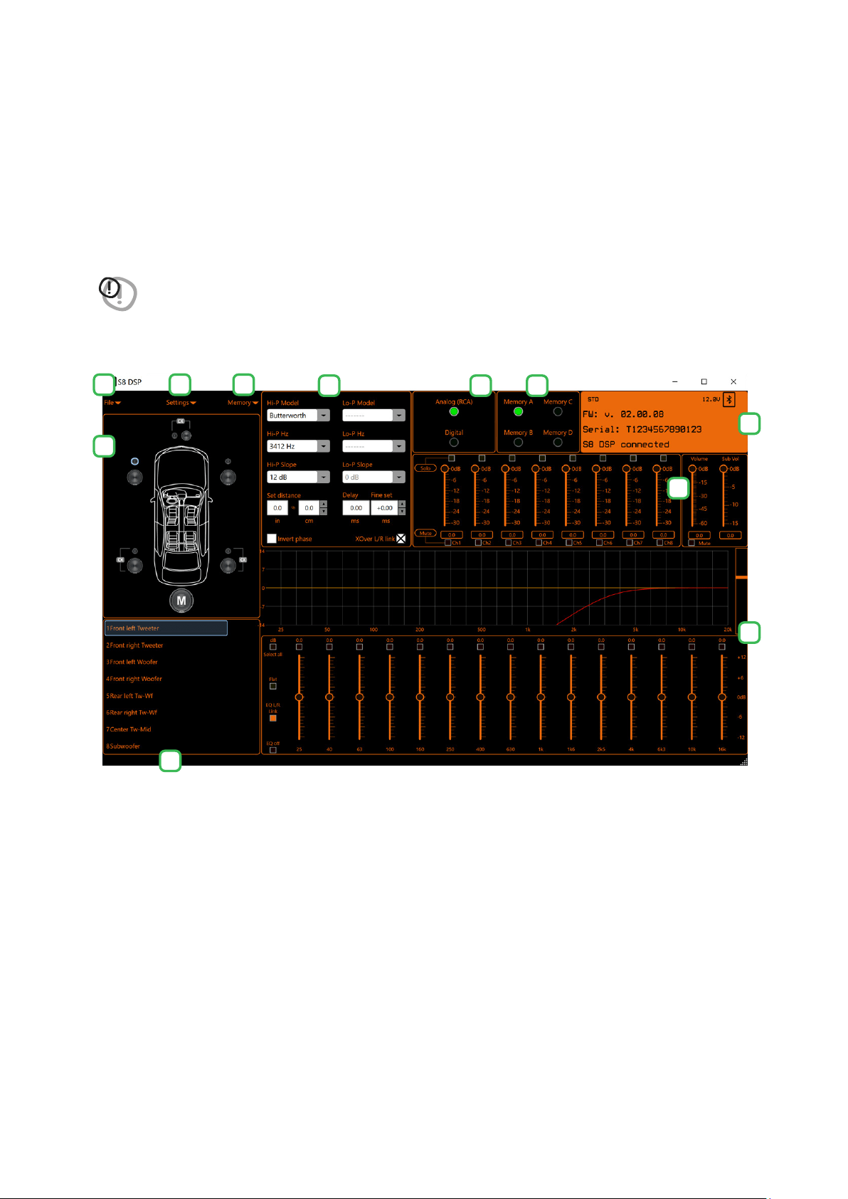
8. S8 DSP SETUP USING A PC/MAC
The software transfers the settings selected during the wizard to the processor’s main memory. If you are using S8 DSP
when connecting for the first time it is advisable to FINALIZE the product, to avoid losing the data stored during the
calibration phase
(see section 8.1.5)
.
At this point the S8 DSP has the correct basic configuration. The functions that allow the acoustic tuning of the
system will be described in the following paragraphs.
WARNING: avoid changing the parameters of the S8 DSP by exploring the functions and, take the time to familiarize
yourself with the possibilities offered by this software.
Adjustments made via the S8 DSP software have an immediate effect on the signal and can, if not carefully
done, damage your system’s speakers.
Remember to make adjustments with a general volume that does not pose a danger to the system speakers.
8
1 2 3
4
5
7
8
6 9 10
11
40
USER’S MANUAL /
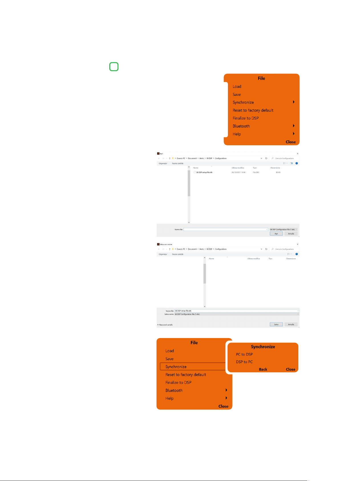
By clicking on the relevant button a drop-down
menu opens up with the items shown in the figure.
8.1 MAIN MENU “FILE”
1
2
3
4
5
6
7
1. Load
this function loads the complete configuration
of the S8 DSP from a previously saved file
(
E.g. “S8 DSP setup file.s8c”
). This function is
available in both CONNECT and OFFLINE mode.
In CONNECT mode this function has the
purpose of being able to reload all the
settings previously saved. This function is
useful in case you want to recover all the
settings made previously, to install another
S8 DSP with the same settings, in order to try
out different acoustic settings.
2. Save
this function saves the complete configuration
of the S8 DSP in a file (
E.g. “S8 DSP setup file.s8c”
),
which can be reloaded later in the S8 DSP
using the “Load” function. This function is
available in both CONNECT and OFFLINE mode.
3. Synchronize, PC/MAC to DSP
or DSP to PC/MAC
these functions synchronize the PC/MAC
with the S8 DSP.
- Press PC/MAC to DSP to load the settings made so far in the memory of the S8 DSP.
- Press DSP to PC/MAC to load the settings in the memory of the S8 DSP on the Control software.
- Press BACK to go back to the “File” menu.
- Press CLOSE to cancel the operation.
8
1
41
USER’S MANUAL /
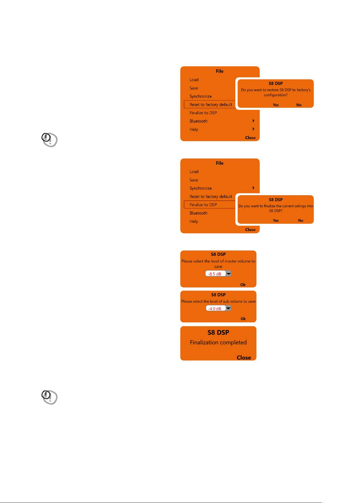
4. Reset to factory default
this function performs a total reset of the S8 DSP
returning the product to its original conditions,
deleting all the data previously saved in the
processor.
Press YES to perform the factory default reset.
Press No to interrupt the operation.
WARNING: the reset restores the system currently used
to the default conditions
(see section 7.4)
.
5. Finalize to DSP
this function allows you to load all the parameters
set during system calibration into the internal memory
of the S8 DSP. This operation allows the S8 DSP to work
without being connected to the PC / MAC.
When Finalize to DSP is run, the software warns
that the data in the S8 DSP will be overwritten:
- click YES to load the data set within the S8 DSP,
overwriting, if present, any data that was
previously saved
- click NO to interrupt the operation.
Remarks: if the Master Volume and Sub Vol levels
are not set to 0dB, you will be prompted for the
level at which the processor will be finalized.
- Click on the drop-down menu to set the desired level.
- Press OK to proceed with finalizing the data on the
device.
- When finalization is complete, press Close to return to the main screen.
WARNING: always run Finalize to DSP before disconnecting the product from your PC / MAC or whenever you exit
the software after system configuration changes have been made. If this is not done, all entered data will be lost.
8
42
USER’S MANUAL /
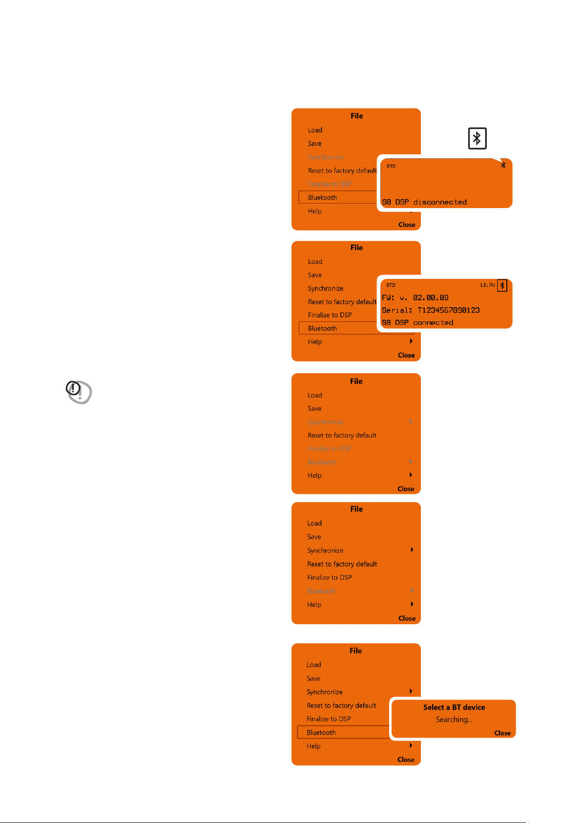
6. Bluetooth
This function is used to connect, disconnect, or
remove the automatic connection of the S8 DPS
to the PC / MAC software.
This function is active if:
1. one or more S8 DSPs turned on nearby are
detected (
the BT symbol will appear at the top
right of the screen “Device Info”
)
(see section 8.11)
2. S8 DSP is already connected to the software
via Bluetooth connection.
6.1 S8 DSP connection to PC/MAC
via Bluetooth connection.
1. Press Bluetooth to start the search for the
S8 DSPs turned on nearby
WARNING: the Bluetooth function is disabled:
- if no S8 DSP is detected nearby.
- if the BT interface of the PC / MAC is not active.
- if S8 DSP is connected to PC / MAC via USB.
8
43
USER’S MANUAL /
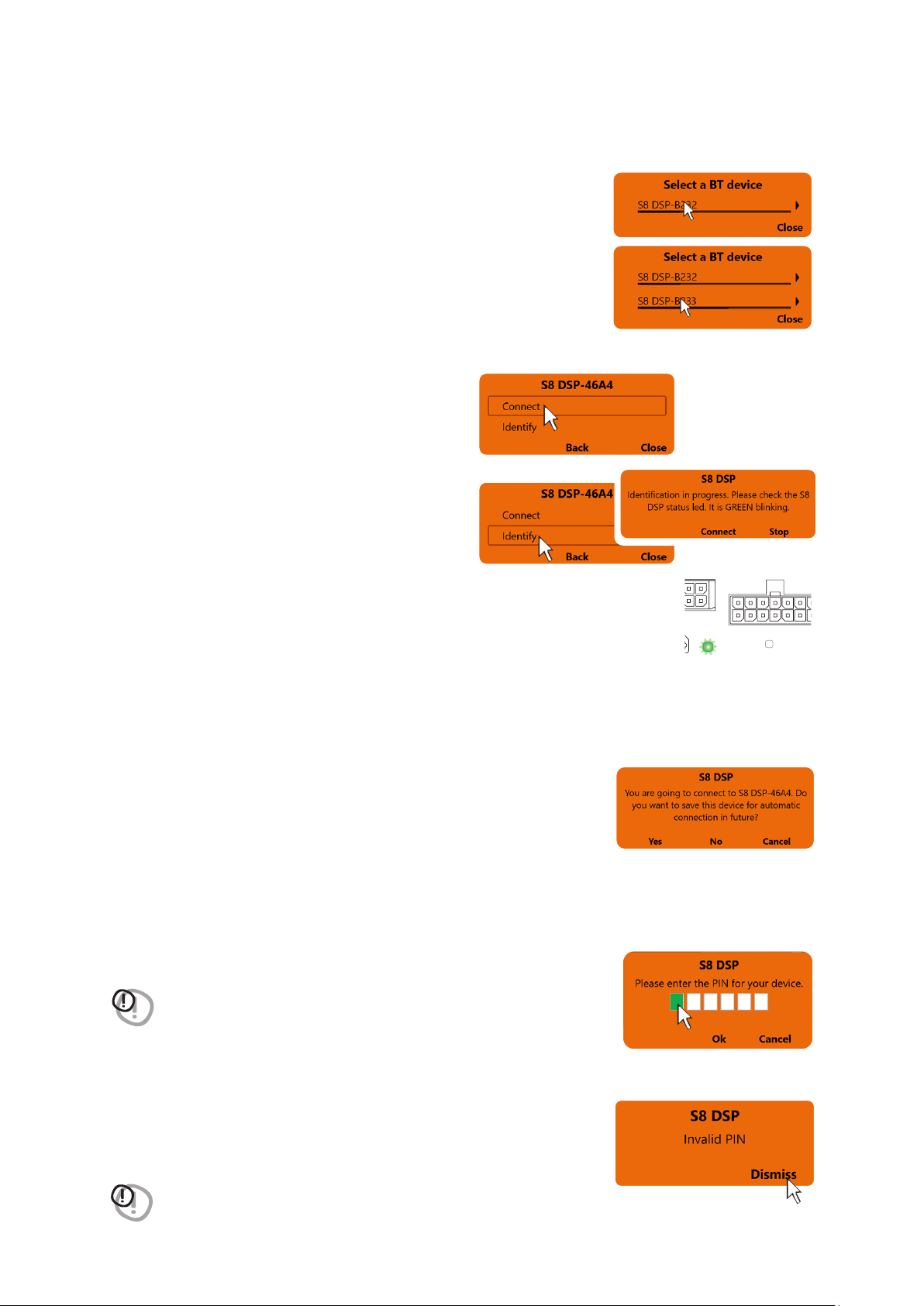
2. Select a BT Device: at the end of the scan, one or more S8 DSPs will be
detected,“
E.g. S8 DSP-XXXX
” (
XXXX is the identification number
of the S8 DSP
)
- click on the name
E.g. S8 DSP-XXXX
to select the processor.
Remark: in the case of more processors available it will be possible later with the
Identify function to check if the selected S8 DSP is the one you want.
- press Close to interrupt the operation.
Remark: when connecting for the first time the software will ask whether to
connect automatically to the S8 DSP selected for any future connections, it
will also avoid the PIN, if enabled
(see section.8.2.8)
.
Remark: you can later remove the automatic connection of the S8 DSP with the function
“Bluetooth>Forget”
(see section.8.1.6.3)
.
- press Yes to connect S8 DSP automatically in the future.
- press No not to connect S8 DSP automatically in the future.
- press Cancel to cancel the operation.
8
- press OK after entering the PIN to access the control software .
- press Cancel to cancel.
Invalid PIN: if the PIN entered is incorrect, the bluetooth connection operation must be repeated from the beginning.
- press Dismiss to return to the main screen.
WARNING: If the Bluetooth PIN has been activated previously
(see section 8.2.8)
click on
the first white box on the left to enter the numbers with the PC / MAC
keyboard
WARNING: if the pin is not available, it is still possible to connect the S8 DSP to the
software via the USB connection.
After selecting S8 DSP, a pop up will appear with the name of the processor.
- press Connect to proceed with the direct connection
of the S8 DSP. The status LED of the selected S8 DSP
will start flashing green.
- press Identify to check if the processor you intend to
connect to is the one you want (
in the case of multiple
S8 DSPs detected
).
- press Connect to proceed with the S8 DSP connection.
- press Stop to go back to the previous window.
- press Back to go back to the previous window.
- press Close to interrupt the operation.
BT
STATUS
SPEAKER IN
PRE IN - DIGITAL IN
44
USER’S MANUAL /
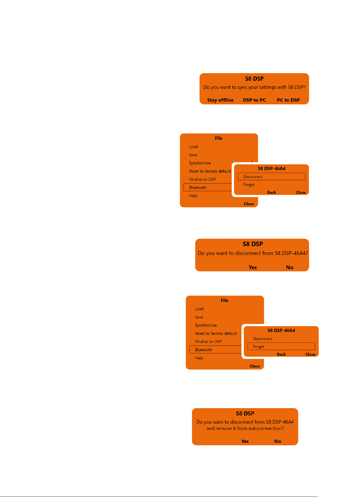
- Press Stay offline to suspend the connection and continue working on the software with the S8 DSP not connected.
- Press DSP to PC/MAC to load the settings stored in the S8 DSP memory onto the software.
- Press PC/MAC to DSP to load the settings made so far on the software into the memory of the S8 DSP
.
If the PIN entered is correct, you will be asked how to connect to the software.
6.2 Disconnect the Bluetooth connection between
S8 DSP and PC/MAC
To disconnect S8 DSP already connected to the
software via Bluetooth connection, while maintaining
the auto connection, use the function
Bluetooth>Disconnect
- press Disconnect to disconnect the S8 DSP.
- press Back to go back to the file menu.
- press Close to cancel the operation and return to the main screen.
- press YES to confirm the disconnection.
- press NO to go back to the previous window.
8
6.3 Disconnect and remove the Bluetooth
auto connection between S8 DSP and PC/MAC
To disconnect and remove the auto connection
of the S8 DSP already connected to the software
via Bluetooth connection, use the function
Bluetooth>Forget
- press Forget to proceed with the disconnection
and removal of the auto connection.
- press Back to go back to the file menu.
- press Close to cancel the operation and return to the main screen.
- press Yes to confirm the disconnection and removal
of the auto connection.
- press NO to go back to the previous window.
45
USER’S MANUAL /
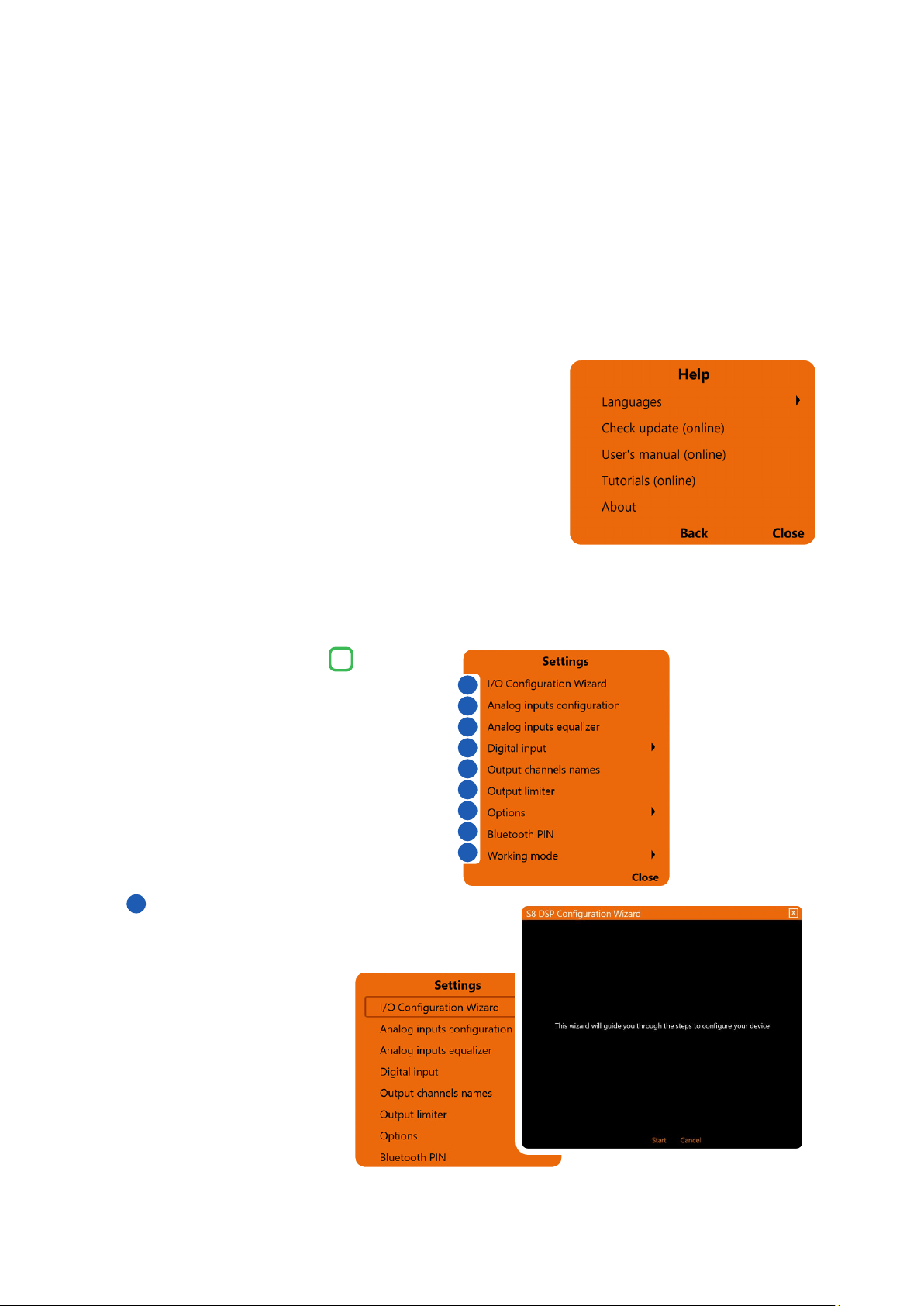
7. Help
Languages: to change the language, select the desired item from the menu, among the available ones.
Check Update (online): this function checks the presence of S8 DSP software / firmware updates by connecting
to the “hertz-audio.com” site
(see section 9.2)
. In order to perform this operation, the PC must have an active
internet connection.
User’s manual (online): the internet browser on the PC will open and the search will automatically start in the
HERTZ download area
, to consult the product manual.
In order to perform this operation, the PC must have an active internet connection.
Tutorials (online): a link is activated on youtube, to consult audio / video information relating to the product.
In order to perform this operation, the PC must have an active internet connection.
About: shows information about the S8 DSP software in use.
8
Cliccando sul relativo pulsante si apre un menù a
tendina con le voci mostrate in figura:
8.2 MAIN MENU “SETTINGS”
I/O Configuration Wizard
It is possible to start the wizard for setting the S8 DSP
(see section 7.5)
.
- press Start to start the wizard.
- press Cancel to interrupt the operation and return to the main screen.
2
1
1
2
3
4
5
6
7
8
9
46
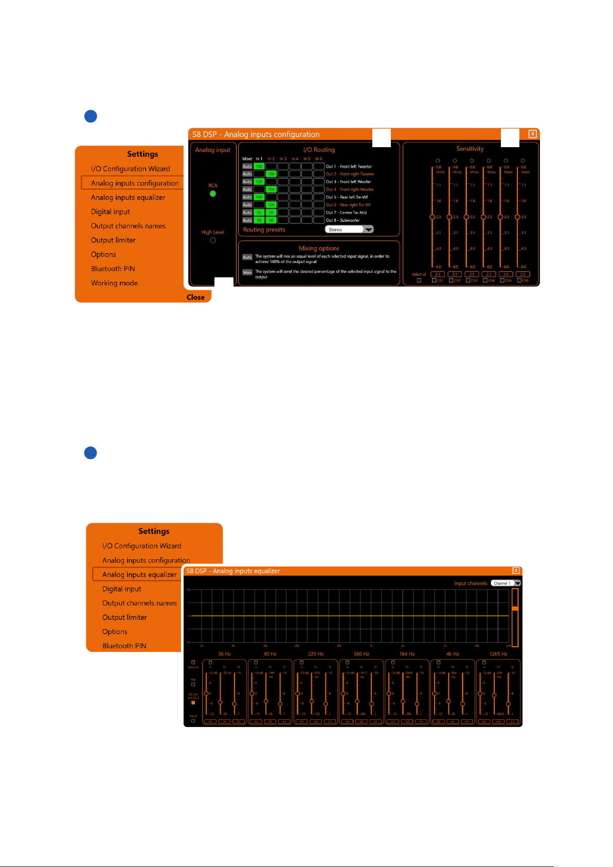
USER’S MANUAL /
Analog Input
It is possible to select the type of analog input used: RCA (PRE IN) or High Level (SPEAKER IN)
(see section. 7.5.4)
.
I/O Routing
It is possible to change the assignment of the input channels on each output channel and adjust the mixing
percentage
(see section. 7.5.5)
.
Sensitivity
It is possible to calibrate the correct sensitivity of the S8 DSP inputs to adapt them to the signal coming from the
source.
(see section 7.5.6)
. The sensitivity scale will vary according to the type of analog input selected:
RCA (0.8 - 6 Vrms) or Hi level (2.5 - 21 Vrms).
Analog inputs configurations
8
2
2
3
3
1
Analog input equalizer
The S8 DSP software provides an input equalizer, which can be managed by a maximum of 7 parametric
equalization poles per channel, this operation is useful for correcting the outputs of OEM HU sources when
they are equalized.
(see section.7.5.7)
.
1
2
3
47
USER’S MANUAL /
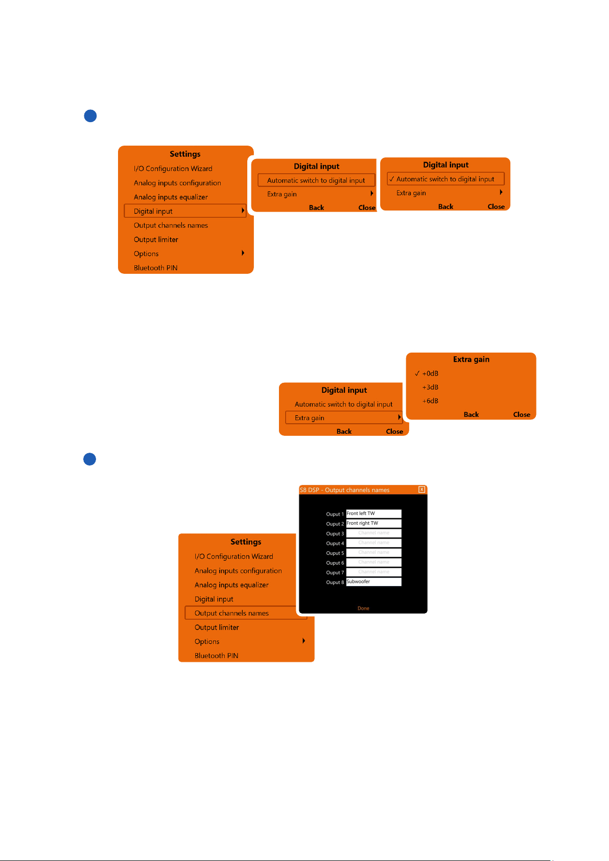
Digital Input
Digital input functions
• Automatic switch to digital input:
by activating this function it is possible to select the optical digital input automatically when the digital audio
signal is detected.
• Extra gain:
it is possible to set the gain of the optical digital input to +0dB (default), + 3dB, +6dB.
8
Outuput channel names
It is possible to name each output channel with a maximum of 15 characters.
Remark: this function is only available if you have selected Free placement as the system mode.
4
5
48
USER’S MANUAL /
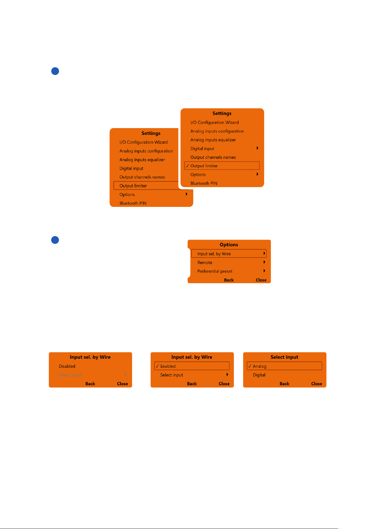
Output Limiter
By activating this function it will be possible to enable the signal limiter on the S8 DSP output.
This function is essential to compensate for transient clipping phenomena, which lead to saturation of the
outputs. The function is disabled by default.
It is possible to activate this function by clicking on Output limiter (a check mark V will appear).
Clicking again on Output Limiter the function will be disabled.
8
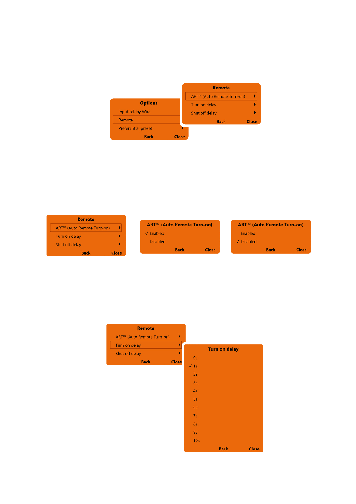
Options
It is possible to select:
1. Input sel by wire
2. Remote
3. Preferential preset
- press Back to go back to the settings menu.
- press Close to cancel the operation and return to the main window.
- press Back to go back to the Options menu.
- press Close to go back to the main window.
- Disabled: the function is not active - Enabled: the function is enabled - Select input: it is possible to
select the selected input when
switching
1. Input sel. By Wire
it is possible to switch to a selected input (Analog or Digital) by connecting the IN SEL terminal to the MEM GND
terminal
(see section 5.1)
Remark: removing the connection between the IN SEL terminal and the MEM GND terminal will restore the
previously active input.
1
2
3
6
7
49
USER’S MANUAL /
- press Back to go back to the Remote menu.
- press Close to go back to the main window.
- select Enabled to enable the
function
- select Disabled to disable the
function
ART (Auto Remote Turn-on)
Turn on delay
Shut of delay
- press Back to go back to the settings menu.
- press Close to interrupt the operation and go back to the main window.
ART (Auto remote turn-on)
It provides the ability to turn on S8 DSP through the amplified output (BTL) of a source connected to the
SPEAKER IN Ch1-Ch2 inputs.
(see section 5.2.3)
2. Remote
It is possible to manage the ART function (Auto Remote Turn-On) and the turn on and off settings of the S8 DSP.
8
- press Back to go back to the Remote menu.
- press Close to go back to the main window.
Turn on delay
it is the delay between switching on the device and the activation of the audio output. Each amplifier has
its own delay in the start-up phase before being operational. By setting Turn On delay to a value equal to or
greater than the longest of these delays, you will have a synchronized start of the audio of the entire system.
50
USER’S MANUAL /
- press Back to go back to the Remote menu.
- press Close to go back to the main window.
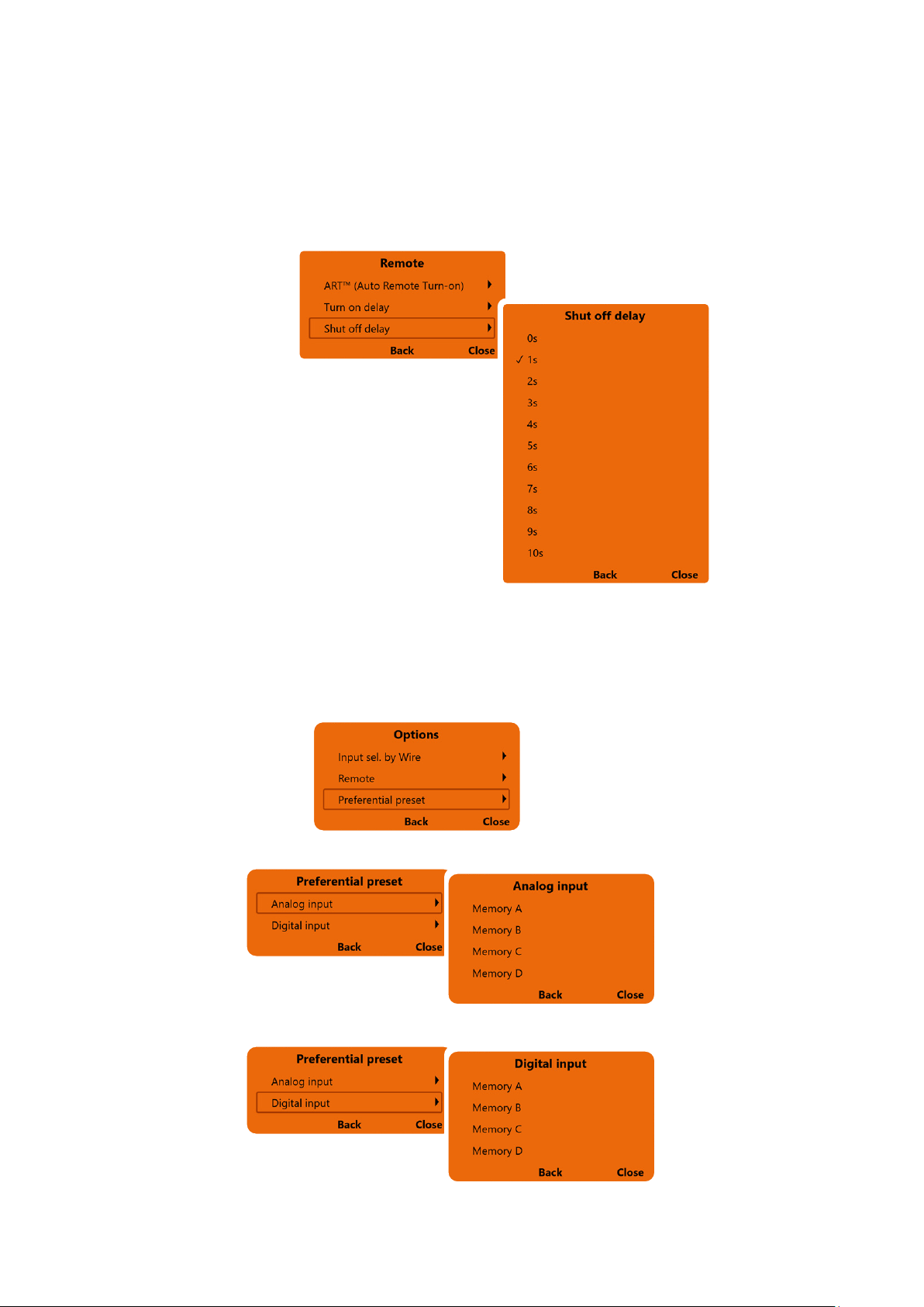
Shut off delay
it is the delay between the deactivation of the REMOTE OUT signal towards the amplifiers and the switching
off of the S8 DSP. It is generally not necessary to act on this parameter but it can be useful if you have amplifiers
that produce a “Bump” when turned off.
8
3. Preferential preset
It provides the ability to associate a memory to the available inputs
(see section 8.3)
.
Select Analog Input to associate a memory from A to D to the Analog input.
Select Digital Input to associate a memory from A to D to the Digital input.
- press Back to go back to the previous menu.
- press Close to go back to the main window.
51
USER’S MANUAL /
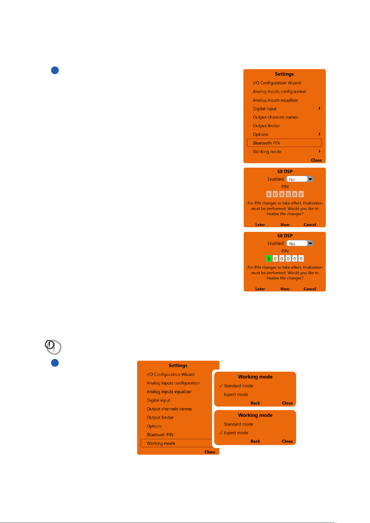
Bluetooth PIN
It provides the ability to manage the PIN for the connection between
S8 DSP and the PC/MAC.
By selecting No on the Enabled drop-down menu, the 6-digit pin request
for the bluetooth connection is disabled.
8
By selecting Yes on the Enabled drop-down menu, the 6-digit pin
request for the bluetooth connection is enabled.
Pin replacement
To replace the PIN (000000 default), click on the first white box on the left
(the box turns green) then enter the numbers chosen for the PIN.
Remark: to make the change effective, you will need to finalize the setup on
the S8 DSP
(see section.8.1.5)
- press Later to subsequently finalize the new setup (the software will keep the changes made in the
bluetooth menu in memory).
- press Now to immediately finalize the new setup.
- press Cancel to interrupt the operation and return to the main menu (the software will not store in the
memory if changes have been made in the bluetooth menu).
WARNING: the Bluetooth PIN function is not available in OFF LINE mode.
• Standard mode: simplified procedure with some constraints that facilitate the use of the software
(see section. 8.6.)
.
• Expert mode: there are no restrictions on the functions to use the software
(see section.8.6)
.
- press Back to go back to the Settings menu.
- press Close to go back to the main window.
Working Mode
8
9
52
USER’S MANUAL /
8
The S8 DSP manages the system configuration by working by default on memory A, giving the ability to save and
recall four memories (A, B, C, D).
(see section.8.10)
In the memories the following data will be stored:
- the filter, time delay and phase settings for each channel;
- the equalization settings for each output channel;
- the output levels of the individual channels.
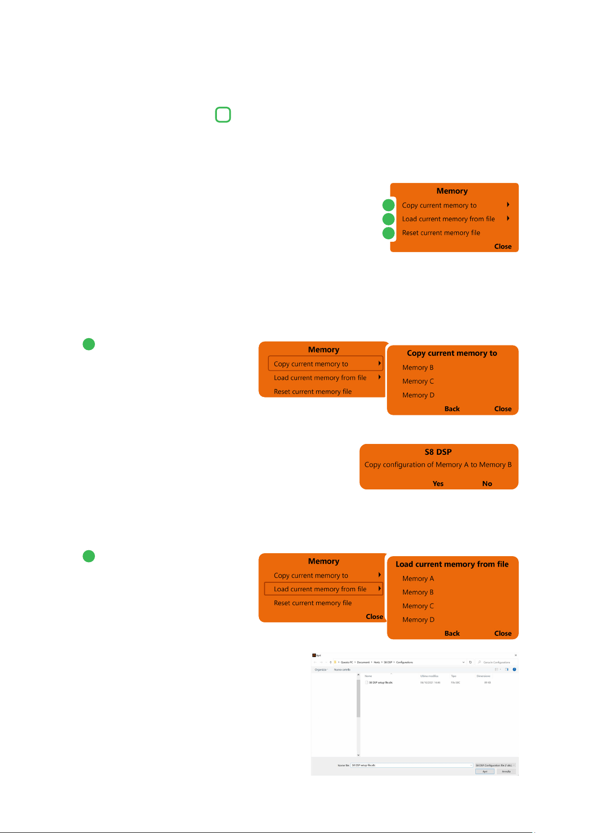
By pressing the MEMORY key on the main menu line, you can access
operations that can be performed between the memories themselves:
8.3 MAIN MENU “MEMORY”
3
Copy current memory to:
allows you to copy the content from one
memory to another.
- select the memory on which to copy the current setting.
- press Yes to confirm.
- press No to cancel.
- press Back to go back to the Memory menu.
- press Close to go back to the main window.
Load current memory from file:
It loads a specific memory by taking
it from a previously saved setup file
(
Eg “S8 DSP setup file.s8c”
), placing it
in the memory you are working on.
- select the memory available in the setup file.
- press Back to go back to the Memory menu.
- press Close to go back to the main window.
1
2
1
2
3
53
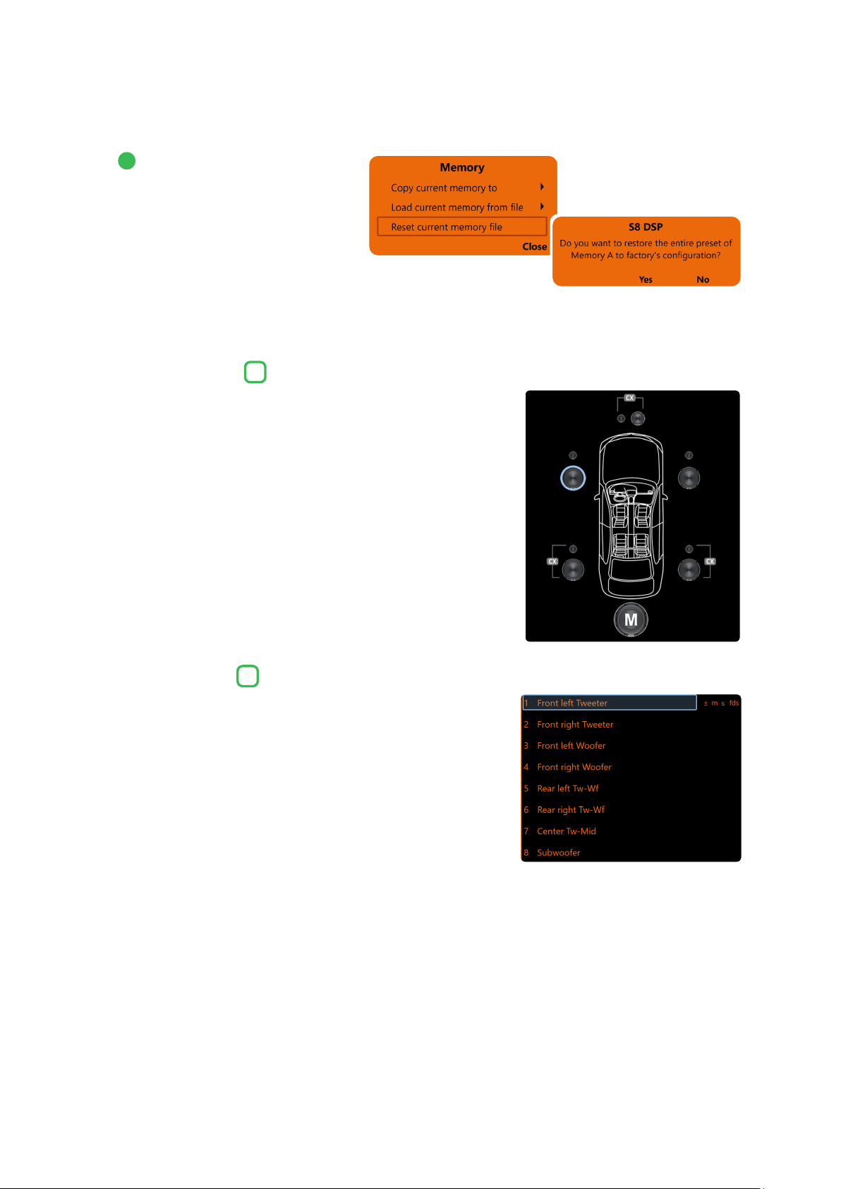
USER’S MANUAL /
Reset current memory file:
It restores the crossover, equalization
and volume levels of the standard
outputs, those that would be proposed
at the end of the configuration procedure.
- press Yes to confirm.
- press No to cancel.
- press Back to go back to the Memory menu.
- press Close to go back to the main window.
In this window you can view both the type and composition of the
system, you can click directly on the speaker or group of speakers to view
or set the parameters of the single channel. Once selected, the speaker/s
will appear highlighted.
In this window you can view both the type and composition of the system,
you can click directly on the description of the speaker or group of speakers
to view or set the parameters of the single channel. Once selected, the
speaker/s will appear highlighted.
- If the MUTE on the channel is active, the message “m” will appear
- If the SOLO function is active, the message “s” will appear
- If there are time delays on the channel, the message “fds” will appear
- If phase inversion has been activated on the channel, the word “±”
will appear.
8.4 CHANNEL MAP
8.5 CHANNEL LIST
4
5
3
8
54
USER’S MANUAL /
S8 DSP manages 8 crossovers, one for each output channel.
Each filter allows you to adjust all the parameters relating to
the channel highlighted in the Channel List.
When starting the software, S8 DSP proposes Butterworth as a standard filter model. By changing the model in Linkwitz or
Bessel, the change will be made only to the channel (mono) or channels (stereo - Xover Link activated) concerned.
8.6 CROSSOVER SETTINGS
6
Xover L/R Link:
with the option enabled, the changes applied to one of the channels
(right or left) will automatically be made to the other as well. Xover
L/R Link affects all Crossover Settings except Set Distance (Delay).
Invert Phase:
it allows you to invert the phase of the selected channel by 180°.
This function can be useful for solving phase alignment problems
between the various filtered channels.
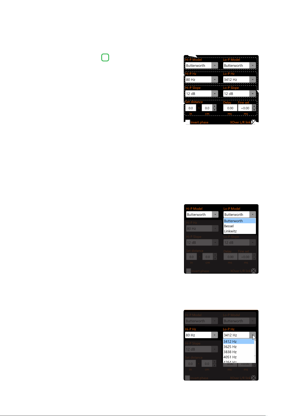
Filter Model:
Hi-P Model / Lo-P Model
- By clicking on the drop-down menus you can select the type of
filter/s applicable to the selected output channel:
- Butterworth
- Bessel
- Linkwitz
Cut Frequency:
By clicking on the drop-down menus you can select the
desired cut-off frequency of the filter (s) applied to the
selected output channel.
Hi-P Hz 20 ÷ 20480: filtro High-Pass
Lo-P Hz 20 ÷ 20480: filtro Low-Pas
2
6
3
4
1
5
1
3
2
4
8
55
USER’S MANUAL /
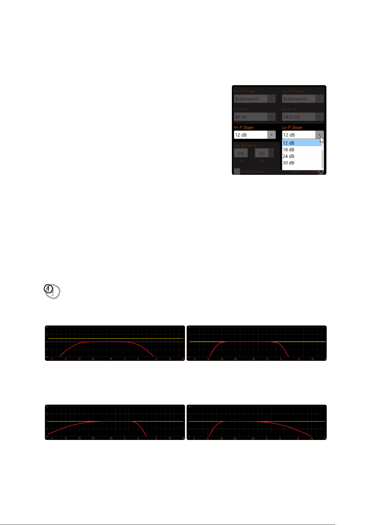
When starting the software, the S8 DSP proposes Butterworth with a standard slope of 12 dB/Oct. By
changing the filter slope, the change will only be made to the channel you are working on.
E.g: if you are adjusting the Front Woofer, the change will affect only this channel (right and left if they are linked).
In STANDARD mode
(see section.8.2.9)
:
Depending on the speaker or speaker system selected during configuration, a suitable type of filter will be available.
E.g.: for the Front Woofer both Hi-P and Lo-P Models will be available, for the Front Tw only Hi-P Model will be
available, etc. An optimized cut-off frequency is set by default to avoid speaker breakdown and limits on
selectable frequencies will be applied.
In EXPERT mode
(see section 8.2.9)
:
Any loudspeaker or speaker system you select has any type of filter and cut-of frequencies available.
Remark: with the slope set to 0dB the filter is disabled.
WARNING: in EXPERT mode, due attention must be paid to filter adjustment. Loudspeakers have mechanical limits
which must not be exceeded and which could lead to their breaking.
The response of the crossover filter for the selected channel is graphically displayed by a red curve,
as in the examples below.
Crossover frequency 80 Hz @ 6 dB Oct.
Hi-pass 2000 Hz @ 24 dB Oct. Low-pass.
Crossover frequency 80 Hz @ 12dB Oct
Hi-pass - 2000 Hz @ 12 dB Oct Low-pass
Crossover frequency 80 Hz @ 24 dB Oct.
Hi-pass 2000 Hz @ 24 dB Oct. Low-pass
Crossover frequency 80 Hz @ 24 dB Oct.
Hi-pass 2000 Hz @ 6 dB Oct. Low-pass.
5
8
Filter Slope:
By clicking on the drop-down menus you can select the slope of the filter/sI applied to the selected output channel.
- Hi-P Slope:
0/6/12/18/24/30 dB/Oct. (Butterworth)
0/6/12/18/24/30 dB/Oct. (Bessel)
0/12/24 dB/Oct. (Linkwitz)
- Lo-P Slope:
0/6/12/18/24/30 dB/Oct. (Butterworth).
0/6/12/18/24/30 dB/Oct. (Bessel).
0/12/24 dB/Oct. (Linkwitz).
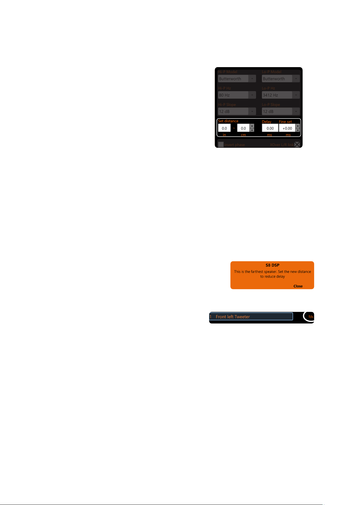
56
USER’S MANUAL /
SET DISTANCE E DELAY:
This setting is based on an automatic system that allows you to
calculate the time it takes for the sound of the speaker to reach the ear.
Preliminary Remarks
sound moves through the air at a speed of 343 m/sec (1,125 ft / sec.)
at a temperature of 20 ° C (68 ° F). If you know the distance of
the sound emission point, it is therefore possible to calculate the
time it takes for the sound to reach the ear. If you set the distances
of the various speakers, the automatic system of the S8 DSP
transforms them into time (ms-milliseconds). It does not assign
the delay (0.0 ms) to the farthest speaker (usually the Subwoofer)
and assigns increasing delays as the position of the other speakers
approaches, so that all emission points can reach the listening
point at the same time.
Fine set and phase delay
The assignment of the delay based on the distance calculation is theoretical. In practice, small variations must
be made due to small distance measurement errors, due to the resonances of the listening environment, and
mainly, due to the speaker phase problem. Two loudspeakers that reproduce two zones of neighbouring frequencies
(
Eg Woofer and Midrange
), in the crossing zone will reproduce the same frequencies at the same time, at an
attenuated level. Due to the different nature of the loudspeakers, these will present a phase diversity which, for
a small frequency range, behaves like a time delay
By operating on “Fine set” it is also possible to partially correct Phase Delay problems.
By operating on the “Fine set” buttons it is possible to change the delay time set automatically. The delay that is
varied is added to (+ x.xx) or reduced from (-x.xx) the value of the delay shown in the “Delay” window, which does
not change the value shown which is the one assigned automatically. Assigning a positive value (+ x.xx) with the
“Fine set” means increasing the delay of that speaker and therefore moving it away from the listening point.
Similarly, assigning a negative value (-x.xx) means decreasing the speaker delay and therefore bringing it closer
to the listening point.
6
By operating on the “fine set” the word “fds” will light up on
the corresponding channel of the “Channel Map” (
Fig.2
).
SET DISTANCE
It allows the user to set the distance between the speaker concerned and the listening point. Choose cm (centimeters)
or in (inches). The “Set Distance” boxes can be set with the cursor using the buttons.
DELAY ms
It displays the time in ms (milliseconds) calculated based on the distance.
FINE SET ms
It displays the time in ms (milliseconds) calculated based on the distance. The S8 DSP’s time delay calculation
system also allows manual fine-tuning. The “Fine set” box can be set with the cursor using the buttons.
To allow you to evaluate how much the “fine set” has changed
manually, both values are shown. To have the resulting delay
value, physically applied to the output, it is necessary to calculate
the algebraic sum of the values shown in the “Delay“ and “Fine set”
boxes. The negative value (decreasing delay) cannot be assigned
to the farthest loudspeaker but only to the others others as they
are already all delayed with respect to it. If you try to give a negative
value to the farthest speaker, an alert message will appear (
Fig.1
).
(Fig.1)
(Fig.2)
8
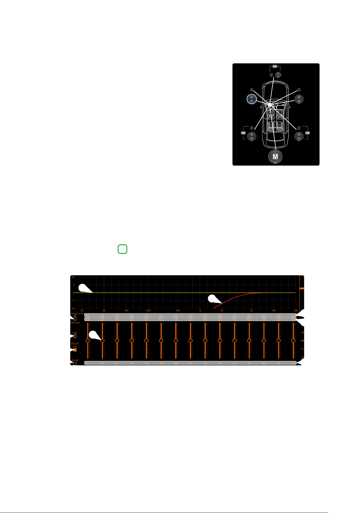
57
USER’S MANUAL /
Example:
setting of time delays on a car (
Fig.3
)
.
1. Select the system listening point. To locate the listening point, choose
an ideal point positioned in the center of the listener’s head (driver or
passenger). For the front and rear center points, choose an intermediate
point between the two listeners.
2. Measure the distance of each speaker or group of speakers with respect
to the listening point in a straight line (as the crow flies). For the single
loudspeaker, choose the center of the mobile membrane as the emission
point. For speaker groups, choose an intermediate point between them.
Subsequently, fine tuning can be performed by selecting the Fine Set unction.
3. Select the channel related to the speaker under consideration on the
Channel Map and enter the related distance value in the Set Distance
box in the Crossover Settings menu.
4. Repeat point 3 for each channel.
5. Once all the time delay settings have been made, start music playback
and adjust the Fine Set box. By moving the values to positive or negative (except the subwoofer because it
is the farthest speaker) you can find the optimal time alignment to have a correct acoustic scene. It is advisable
to listen to different types of musical tracks (percussion, melodic, etc.) for a more correct evaluation of the
coherence (spatial stability) of the various musical instruments
6. Once the time alignment procedure has been completed, it is possible to intervene on the output equalizer
(see section 8.7)
,
to optimize the system response according to the level alignment at the various frequencies.
Remark: the measurements for the previous operations can also be carried out instrumentally by means of a spectrum
analyzer equipped with a special microphone. The result must in any case be evaluated and optimized with listening
tests.
The S8 DSP software provides an output equalizer, which can be managed by up to 15 equalization bands for each channel.
Through the EQ Fine Tuning function it is possible to make a parametric adjustment for each band.
Equalization bands: by operating the sliders it will be possible to adjust the gain of the selected band
(Gmin + 12dB ÷ Gmax -12dB), by double clicking on the slider it is possible to restore the gain to 0dB.
dB: this part of the screen displays the Gain (dB) values set for each equalization band.
By clicking on the buttons it is possible to select a group of equalization bands for which the Gain levels can be
adjusted at the same time. By clicking on the button again, the function will be disabled.
Hz: in this part of the screen the frequency values Fo (Hz) set for each equalization band are displayed.
Select all: by clicking on the “Select all” button it will be possible to adjust all the Gain levels of the equalization
bands at the same time. By clicking on the “Select all” button again, the function will be disabled.
Flat: by clicking on the Flat button, the gains of all bands will be returned to the 0 dB position.
EQ L/R Link: when active, it applies the equalization curve of the left channel to the right channel or vice versa.
EQ off: by clicking on the EQ off button, the equalizer on the selected channel or 2 channels (EQ Link active) is
disabled to check the effect without losing the settings. By clicking on the “EQ off” button again, the function
will be disabled.
It is the equalization curve that will be applied to the output signal.
It is the electrical response curve of the output signal subjected to filtering (XOVER) and equalization.
8.7 OUTPUT EQUALIZER
7
(Fig.3)
5
9
10
6
7
8
4
2
3
1
1
5
3
7
9
2
6
4
8
10
8
110 cm
116 cm106 cm
100 cm90 cm
127 cm106 cm
164 cm
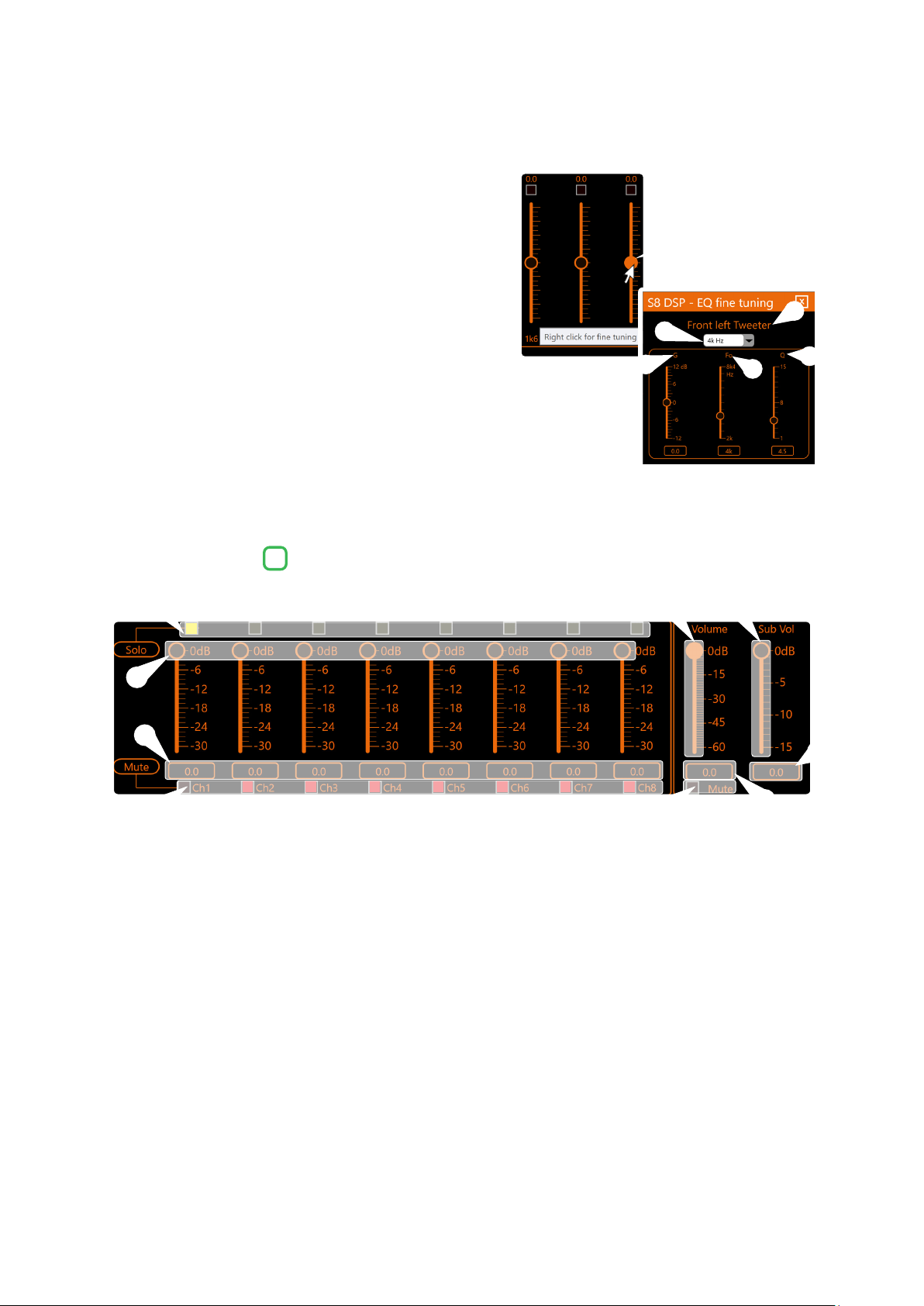
58
USER’S MANUAL /
EQ Fine Tuning parametric adjustment. It is possible to change
the parameters of each equalizer band clicking with the right
mouse button on the slider, after that “fine tuning” will appear
next to it, then click with the left button on the wording
to open the “EQ Fine Tuning” menu.
in this part of the screen the name of the output channel
being equalized is displayed.
in this drop-down menu, by selecting the frequency,
it is possible to change the band (s) of the equalizer on
which to intervene.
G (dB): by operating the “G” slider, it will be possible to make
adjustments to the gain of the selected band (Gmin +12dB ÷ Gmax -12dB).
Fo (Hz): By operating on the “Fo” slider, it will be possible to make adjustments
to the frequency of the selected band.
Q: By operating on the “Q” slider, it will be possible to make adjustments to the “Q”
quality factor of the selected band (Q: 1 ÷ 15 step min 0.1).
This section shows the settings relating to the output levels of the S8 DSP active channels on the screen.
By operating on one of the sliders belonging to the output channels, it will be possible to adjust the output level
(-30 ÷ 0 dB) for each channel.
This part of the screen shows the output level of each individual channel (-30 ÷ 0 dB), referring to the position of
the output channels slider.
By clicking on the “Mute” button it will be possible to mute the output channels referred to it.
By clicking on the “Mute” button again, the mute function will be deactivated.
By clicking on the “Solo” button it will be possible to mute the output channels excluding the activated one.
By manually clicking on the “Solo” button this function will be disabled.
By operating on the “Volume” slider, it will be possible to make adjustments to the overall system output level (-60
÷
0 dB).
By acting on the “Sub Volume” slider it will be possible to adjust the subwoofer output level (-15 ÷ 0 dB), if present
in the system.
This part of the screen indicates the general output level of the system (-60 ÷ 0 dB)
.
This part of the screen indicates the subwoofer output level (-15 ÷ 0 dB)
.
By clicking on the “Mute” button it will be possible to mute the general output.
8.8 OUTPUT LEVEL
8
5
5
4
4
1
1
2
2
3
3
8
1
3
9
2
4
5
6
7
8
5
6
7
8
9
4
1
2
3
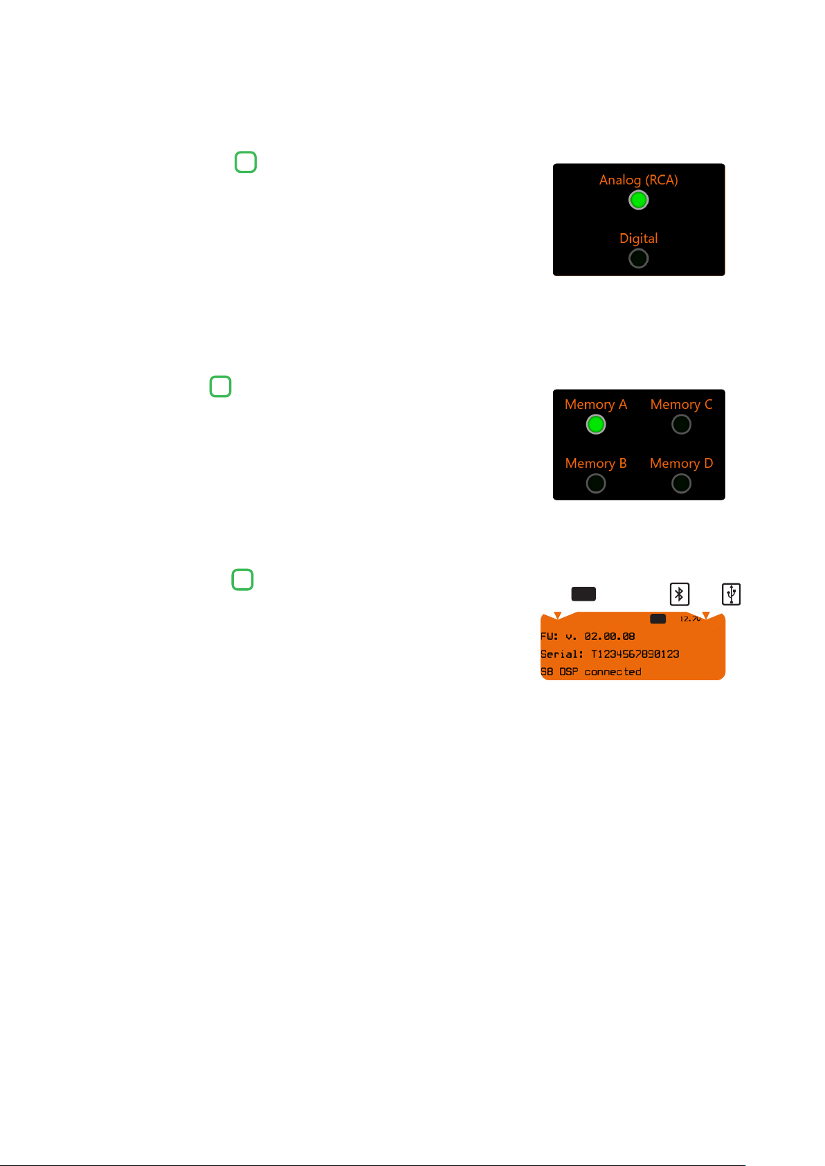
59
USER’S MANUAL /
The window will show and give the possibility to select the active input
source when connecting with the PC/MAC.
The S8 DSP manages the system configuration by working by default on memory
A, but provides the ability to save and recall four memories (A, B, C, D).
This window shows:
● if you are using the software in STANDARD or EXPERT mode
(see section. 8.2.9)
● if the ART function is activated
(see section. 8.2.7.2.)
● if the LIMITER function is activated
(see section. 8.2.6)
● the battery voltage
● the connection mode to the PC/MAC: USB or BT
(see section. 7.2 - 7.3)
● the device Firmware version
● the device Serial Number
● if S8 DSP is connected to the PC/MAC
● the Input clipping indicator (CLIP)
8.9 SELECT INPUT
8.10 MEMORY
8.11 DEVICE INFO
9
10
11
8
ART LIM
oror
STD EXP
CLIP

60
USER’S MANUAL /
9. TROUBLESHOOTING
1. S8 DSP operating problems
If, when calibrating the system with S8 DSP connected to a PC/MAC there are operating problems, try
disconnecting the PC/MAC power supply cable. With the PC/MAC working on battery power you avoid a possible
voltage difference in the USB ground between the processor and the ground (PC).
2. Connection lost between S8 DSP and PC/MAC
If, while calibrating the system with the PC/MAC connected to S8 DSP, the processor is turned off and back on again,
the connection is lost and the software cannot finalize the adjustments that were set. To avoid losing the
settings, proceed as follows:
a- Save the setup to a file on the PC/MAC using the FILE/SAVE function.
b- Exit the software.
c- Turn S8 DSP on.
d- Launch the software again.
e- Load the setup file again that was saved using the FILE/LOAD function
3. S8 DSP does not respond
If, while calibrating the system with the PC/MAC connected to S8 DSP, the processor does not respond to the
commands, proceed as follows:
a- turn S8 DSP off:
- by disconnecting the Remote IN, or
- by briefly disconnecting the power supply cable;
b- Save the setup to a file on the PC using the FILE/SAVE function;
c- Exit the software;
d- Turn the S8 DSP on;
e- Launch the software again;
f- Load the setup file again that was saved using the FILE/LOAD function
4. Settings not stored
In order to successfully complete the S8 DSP setup and not lose the settings performed, remember to store the
selected settings. Select File from the main software menu via the PC and then choose Finalize to S8 DSP
.
Loud whistle / background hiss.
In case a loud whistle / background hiss can be heard, it may be necessary to repeat the input sensitivity setup and / or
to rectify the output levels adjustment. For more information,
(see sections. 7.5.6 - 8.8)
.
9.1 BACKGROUND NOISE
9
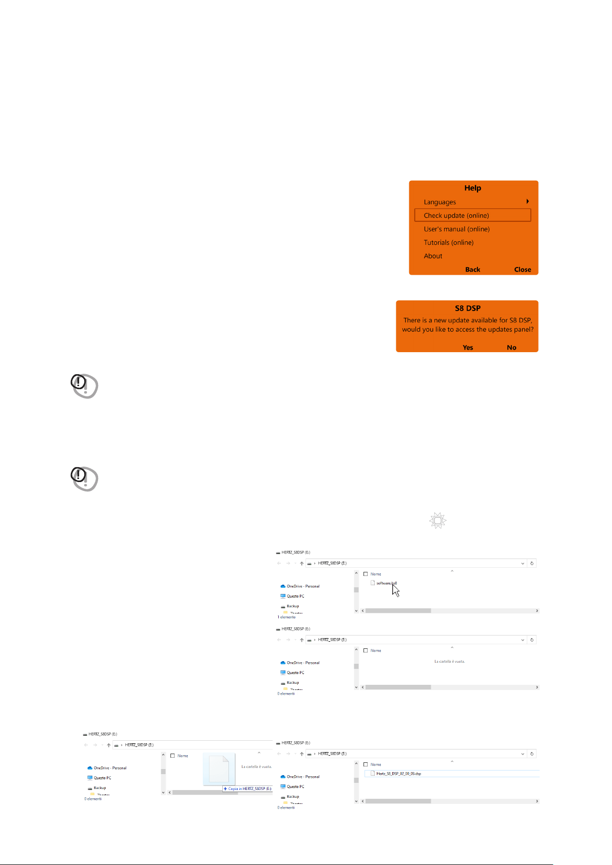
61
USER’S MANUAL /
If there are product UPGRADES available online, proceed as follows:
- Save the previous setup (if you wish to consult it in OFFLINE mode);
1. Start the S8 DSP software
2. Access the “Help” menu and select
“Check updates”
3. When selecting “Check updates”, if there are updates available,
the following window will appear:
- press Yes to open the internet browser on the PC/MAC where the search
for the
HERTZ download area
will automatically start.
- press No to cancel the operation.
WARNING: it is necessary to download the files manually from the website.
The method of accessing the software may differ from the one described below.
Refer to the instructions on the website
4. Once the relevant page is open, click on the appropriate product LINK.
5. Locate the most updated file named “Hertz_S8_DSP_xx_xx_xx.dsp” and click on the specific symbol to start
the download. When prompted, save the file on your PC.
WARNING: S8 DSP Firmware update procedure may be delicate. It is extremely important that it is performed under
the best possible conditions. If the operation is started and prematurely interrupted (
E.g.: PC locked up,
accidental disconnection of the USB cable during update
), our After Sales Service might need to be contacted to
reprogram the S8 DSP.
6. To perform the update:
- Turn S8 DSP off (led status off);.
- Connect the USB cable from PC/MAC to S8 DSP (white color led status);
- S8 DSP will be acknowledged by PC/MAC
as a USB mass storage device
“HERTZS8DSP (X :)” with a file name
“software.hs8” inside;
- Cancel the file “software.hs8”;
- Copy the “Hertz_S8_DSP_xx_xx_xx.dsp” file previously downloaded to the PC/MAC into the empty folder.
Wait for the transfer to complete.
9.2 FIRMWARE UPGRADE
STATUS
9

62
USER’S MANUAL /
- close the window, perform a “safe removal of hardware and eject
media” to eject the USB device “HERTZS8DSP (X :)”;
- disconnect the USB from the processor
7. Turn S8 DSP on
- Start the PC/MAC software and connect the processor
(see section.7.2 - .7.3)
- Check that the firmware version (FW: v. Xx.xx.xx) on the “Device Info”
window corresponds to the one previously downloaded and copied
into the processor (“Hertz_S8_DSP_xx_xx_xx.dsp”).
9
ART LIM

63
USER’S MANUAL /
10. TECHNICAL SPECIFICATIONS
POWER SUPPLY
Nominal Power supply voltage / fuse: 7 ÷ 20 VDC 1A
Pulse operating voltage: 5 ÷ 24 VDC
Idling current: 0.34 A
OFF current (ART
TM
= OFF): <80 µA
OFF current (ART
TM
= ON): <80 µA
Remote IN: 6 ÷ 20 VDC (10 mA)
Remote OUT: 4 ÷ 20 VDC (150 mA)
ART - Automatic Remote Turn on/off from OUTPUT BTL speakers (Selectable): 1.5 ÷ 7 VDC
SIGNAL STAGE
Distortion - THD @ 1 kHz, 1 VRMS Output: 0.004 %
Bandwidth @ -3 dB: 10 Hz ÷ 40 kHz
S/N ratio @ A weighted, 4 V Output, 1 V Master Input: 100 dBA
S/N ratio @ A weighted, 4 V Output, 1 V Digital IN Input: 112 dBA
Channel Separation @ 1 kHz: 97 dBA
Input sensitivity Pre-In: 0.8 ÷ 6 VRMS
Input sensitivity Speaker-In: 2.5 ÷ 21 VRMS
Input Impedance: 10 kΩ (Pre IN/AUX) 4,7 Ω (Speaker IN)
Max output Level 0,1%THD: 4 V
INPUTS STAGE
Low level (Pre): Ch1 ÷ Ch6 Input/Output Matrix Routing
Hi-Level: Ch1 ÷ Ch6
Digital IN: 1 x Optical S/PDIF; Max 96 kHz / 24 bit; Extra Gain +3 dB, + 6 dB
OUTPUT STAGE
Low level (Pre Out): Ch1 ÷ Ch8;
Output Equalizer 15 poles Parametric EQ: ±12 dB; 20 ÷20 kHz
CONNECTION
From / to personal computer: 1 x micro USB
Bluetooth data connectivity (no audio): BT 5.0 (BLE)
CROSSOVER
Filter type: Full / Hi-Pass / Low-Pass / Band Pass
Filter mode and slope: Linkwitz @ 12 / 24 dB
Butterworth @ 6 / 12 /18 / 24 / 30 dB
Bessel @ 6 / 12 /18 / 24 / 30 dB
Crossover frequencies: 20 ÷ 20 k Hz (120 step)
Phase control: 0° / 180°
EQUALIZER (20 HZ ÷ 20 kHz)
Inputs: Parametric EQ: +12 dB ÷ -12 dB; 7 poles (for each input channel)
Outputs: Parametric EQ: +12 dB ÷ -12 dB; 15 poles (for each output channel)
GENERAL
Memory Preset: 4 x Preset
Memory Preset selection: Through the Control Software or by wire
TIME ALIGNMENT
Distance: 0 ÷ 471,5 cm / 0 ÷ 185.5 in.
Delay: 0 ÷ 13,58 cm
Step: 0,02 ms, 0,7 cm / 0.27 in.
GENERAL REQUIREMENTS
PC connections: 1 x USB 1,1 / 2,0 / 3,0 Compatible or Bloutooth 5.0 BLE
Software / PC requirements: Microsoft Windows (32/64 bit): Windows 8 (USB Only)
Windows 10 (USB and BT BLE)
Mac Os: 10.13 Hight Sierra or later
Minimum mobile device requirements: Android OS 7 or later, iOS 12 or later
Video Resolution with screen resize min. 1024 x 600
Ambient operating temperature range 0° C to 55° C / (32° F to 131° F)
SIZE / WEIGHT
Max size W x H x D (mm/inch): 130 x 37 x 88,3 / 5.12 x 1.45 x 3.48
Weight (kg/lb): 0,66
/ 1.45
10

Tutte le specifiche riportate sono soggette a cambiamento senza preavviso
PART OF ELETTROMEDIA
62018 Potenza Picena (MC) Italy
T +39 0733 870 870 - F +39 0733 870 880
elettromedia.com
hertz-audio.com