Loading ...
Loading ...
Loading ...
57
USER’S MANUAL /
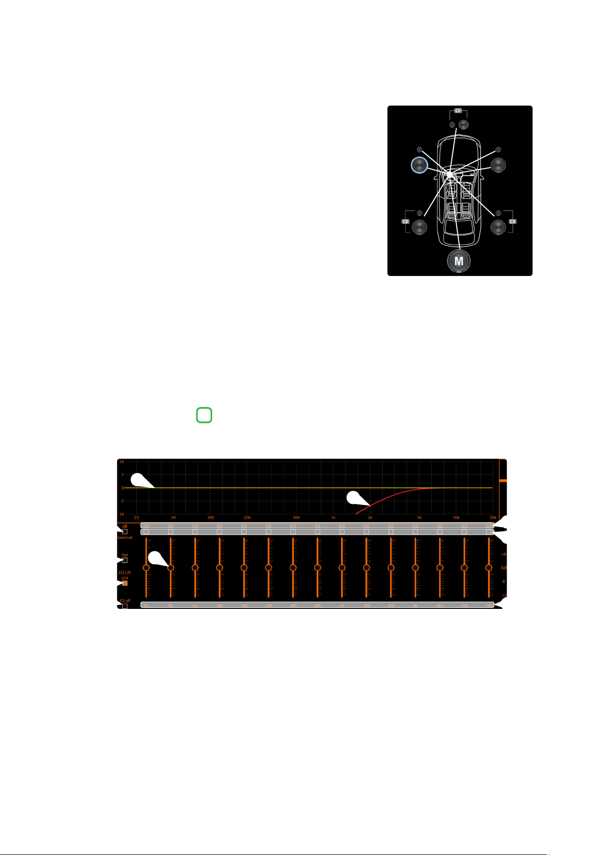
Example:
setting of time delays on a car (
Fig.3
)
.
1. Select the system listening point. To locate the listening point, choose
an ideal point positioned in the center of the listener’s head (driver or
passenger). For the front and rear center points, choose an intermediate
point between the two listeners.
2. Measure the distance of each speaker or group of speakers with respect
to the listening point in a straight line (as the crow flies). For the single
loudspeaker, choose the center of the mobile membrane as the emission
point. For speaker groups, choose an intermediate point between them.
Subsequently, fine tuning can be performed by selecting the Fine Set unction.
3. Select the channel related to the speaker under consideration on the
Channel Map and enter the related distance value in the Set Distance
box in the Crossover Settings menu.
4. Repeat point 3 for each channel.
5. Once all the time delay settings have been made, start music playback
and adjust the Fine Set box. By moving the values to positive or negative (except the subwoofer because it
is the farthest speaker) you can find the optimal time alignment to have a correct acoustic scene. It is advisable
to listen to different types of musical tracks (percussion, melodic, etc.) for a more correct evaluation of the
coherence (spatial stability) of the various musical instruments
6. Once the time alignment procedure has been completed, it is possible to intervene on the output equalizer
(see section 8.7)
,
to optimize the system response according to the level alignment at the various frequencies.
Remark: the measurements for the previous operations can also be carried out instrumentally by means of a spectrum
analyzer equipped with a special microphone. The result must in any case be evaluated and optimized with listening
tests.
The S8 DSP software provides an output equalizer, which can be managed by up to 15 equalization bands for each channel.
Through the EQ Fine Tuning function it is possible to make a parametric adjustment for each band.
Equalization bands: by operating the sliders it will be possible to adjust the gain of the selected band
(Gmin + 12dB ÷ Gmax -12dB), by double clicking on the slider it is possible to restore the gain to 0dB.
dB: this part of the screen displays the Gain (dB) values set for each equalization band.
By clicking on the buttons it is possible to select a group of equalization bands for which the Gain levels can be
adjusted at the same time. By clicking on the button again, the function will be disabled.
Hz: in this part of the screen the frequency values Fo (Hz) set for each equalization band are displayed.
Select all: by clicking on the “Select all” button it will be possible to adjust all the Gain levels of the equalization
bands at the same time. By clicking on the “Select all” button again, the function will be disabled.
Flat: by clicking on the Flat button, the gains of all bands will be returned to the 0 dB position.
EQ L/R Link: when active, it applies the equalization curve of the left channel to the right channel or vice versa.
EQ off: by clicking on the EQ off button, the equalizer on the selected channel or 2 channels (EQ Link active) is
disabled to check the effect without losing the settings. By clicking on the “EQ off” button again, the function
will be disabled.
It is the equalization curve that will be applied to the output signal.
It is the electrical response curve of the output signal subjected to filtering (XOVER) and equalization.
8.7 OUTPUT EQUALIZER
7
(Fig.3)
5
9
10
6
7
8
4
2
3
1
1
5
3
7
9
2
6
4
8
10
8
110 cm
116 cm106 cm
100 cm90 cm
127 cm106 cm
164 cm
Loading ...
Loading ...
Loading ...