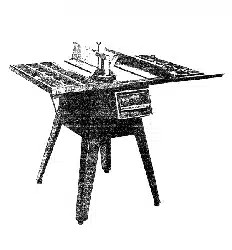
Loading ...
Loading ...
Loading ...
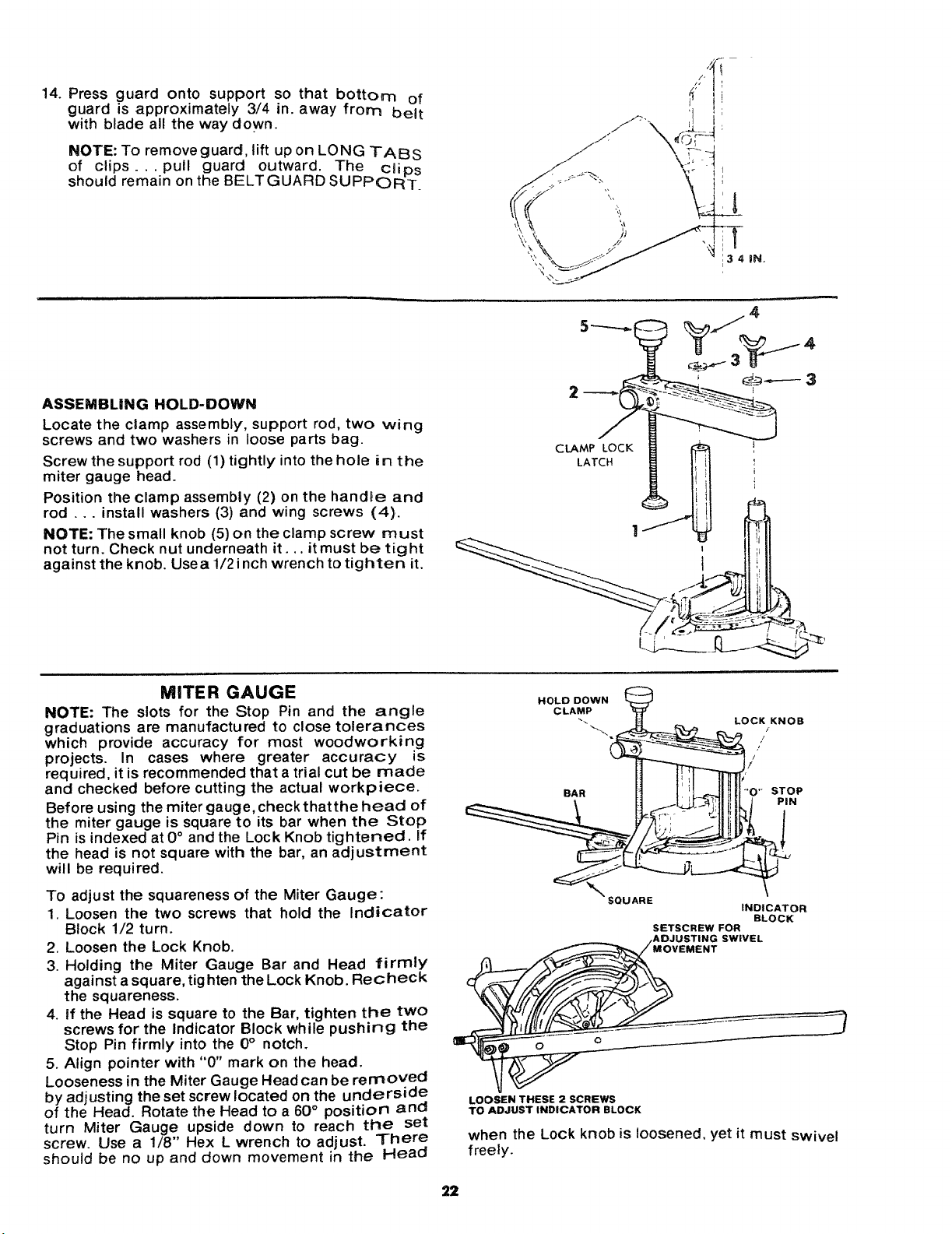
14. Press guard onto support so that bottom of
guard is approximately 3/4 in. away from belt
with blade all the way down.
NOTE: To remove guard, lift up on LONG TABS
of clips.., pull guard outward. The ciips
should remain on the BELTGUARD SUPPORT,
f
/S/_ --
l
:341N.
ASSEMBLING HOLD-DOWN
Locate the clamp assembly, support rod, two wing
screws and two washers in loose parts bag.
Screw the support rod (1) tightly into the hole in the
miter gauge head.
Position the clamp assembly (2) on the handle and
rod ... install washers (3) and wing screws (4).
NOTE: The small knob (5) on the clamp screw must
not turn. Check nut underneath it... itmust be tight
against the knob. Use a 1/2 inch wrench to tighten it.
2
MITER GAUGE
NOTE: The slots for the Stop Pin and the angle
graduations are manufactured to close tolerances
which provide accuracy for most woodworking
projects. In cases where greater accuracy is
required, it is recommended that a trial cut be made
and checked before cutting the actual workpiece.
Before using the miter gauge, checkthatthe head of
the miter gauge is square to its bar when the Stop
Pin is indexed at 0° and the Lock Knob tightened, if
the head is not square with the bar, an adjustment
will be required.
To adjust the squareness of the Miter Gauge:
1. Loosen the two screws that hold the Indicator
Block 1/2 turn.
2. Loosen the Lock Knob.
3. Holding the Miter Gauge Bar and Head firmly
against a square, tighten the Lock Knob. Recheck
the squareness.
4. if the Head is square to the Bar, tighten the two
screws for the Indicator Block while pushing the
Stop Pin firmly into the 0° notch.
5. Align pointer with "0" mark on the head.
Looseness in the Miter Gauge Head can be removed
by adjusting the set screw located on the underside
of the Head. Rotate the Head to a 60° position and
turn Miter Gauge upside down to reach the set
screw. Use a 1/8" Hex L wrench to adjust. There
should be no up and down movement in the Head
HOLD DOWN
CLAMP
BAR STOP
PiN
" SQUARE
INDICATOR
BLOCK
SETSCREW FOR
. sw,vEL
LOOSEN THESE 2 SCREWS
TO ADJUST INDICATOR BLOCK
when the Lock knob is loosened, yet it must swivel
freely.
22
Loading ...
Loading ...
Loading ...