Loading ...
Loading ...
Loading ...
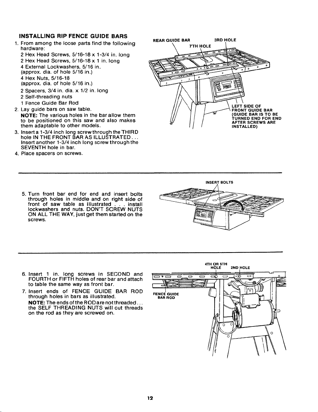
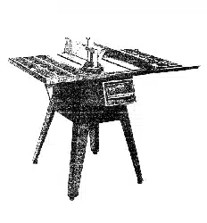
iNSTALLING RIP FENCEGUIDEBARS
1.Fromamongtheloosepartsfind thefollowing
hardware:
2HexHeadScrews,5/16-18x 1-3/4in.long
2HexHeadScrews,5/16-18x 1 in.long
4 ExternalLockwashers,5/16in.
(approx.dia.of hole5/16in.)
4 HexNuts,5/16-18
(approx.dia.of hole5/16in.)
2Spacers,3/4in.dia.x 1/2in.long
2Self-threadingnuts
1FenceGuideBarRod
2.Layguidebarson sawtable.
NOTE:Thevariousholesin thebarallowthem
to bepositionedon this sawandalsomakes
them adaptable to other models.
3. Insert a 1-3/4 inch long screwthroughtheTHIRD
hole IN THE FRONT BAR AS ILLUSTRATED...
insert another 1-3/4 inch long screw through the
SEVENTH hole in bar.
4. Place spacers on screws.
REAR GUIDE BAR
7TH HOLE
3RD HOLE
LEFT SIDE OF
FRONT GUIDE BAR
(GUIDE BAR IS TO BE
TURNED END FOR END
AFTER SCREWS ARE
INSTALLED)
5. Turn front bar end for end and insert bolts
through holes in middle and on right side of
front of saw table as illustrated install
Iockwashers and nuts. DON'T SCI_I:;W NUTS
ON ALL THE WAY, just get them started on the
screws.
INSERT BOLTS
6. Insert 1 in. long screws in SECOND and
FOURTH or FIFTH holes of rear bar and attach
to table the same way as front bar.
7. Insert ends of FENCE GUIDE BAR ROD
through holes in bars as illustrated.
NOTE: The ends of the RODare not threaded...
the SELF THREADING NUTS will cut threads
on the rod as they are screwed on.
FENCE GUIDE
BAR ROD
4TH OR 5TH
HOLE 2ND HOLE
12
Loading ...
Loading ...
Loading ...