Loading ...
Loading ...
Loading ...
64 | City Series CC40E-11
installation
919-696 08.10.16
1. Stretch out both inner 4" (102 mm) and outer 6 7/8" (175 mm) pipe up to
a maximum of 20 feet.
Note :The inner and outer pipes may be cut if only a short length is required.
2. Install spring spacers around 4" (102 mm) inner pipe as shown.
Slide outer flex pipe over and all the way down the 4" pipe.
3. Apply a bead of Mill Pac around the perimeter of the 4" (102 mm)
inner collar of the flex adapter and slip the 4" (102 mm) inner flex pipe
from the Vertical termination kit over the flex adapter ensuring that the
inner flex pipe overlaps the collar by at least 1-3/8" (35 mm). Fasten with
3 screws.
4. Apply a bead of Mill Pac around the perimeter of the 6-7/8" (175 mm)
outer collar of the flue adapter and slip it over the 6-7/8" (175 mm) outer
flex pipe from the vertical termination kit ensuring that the outer flex pipe
overlaps the collar by at least 1-3/8" (35 mm). Fasten with the 3 screws.
5. Repeat steps to secure the other end of the flex adapter using the flex kit.
6. See Vertical Vent installation instructions for installation of the complete
vent system.
Note: If an offset is necessary in the attic or floor joists it is important to
sup-port the vent pipe every 3 feet (0.91 m) to avoid excessive stress and
sagging of the vent pipe. Wall straps are provided (3 in total) for this
purpose.
All round/plumbers strapping may also be used if further supports are
required.
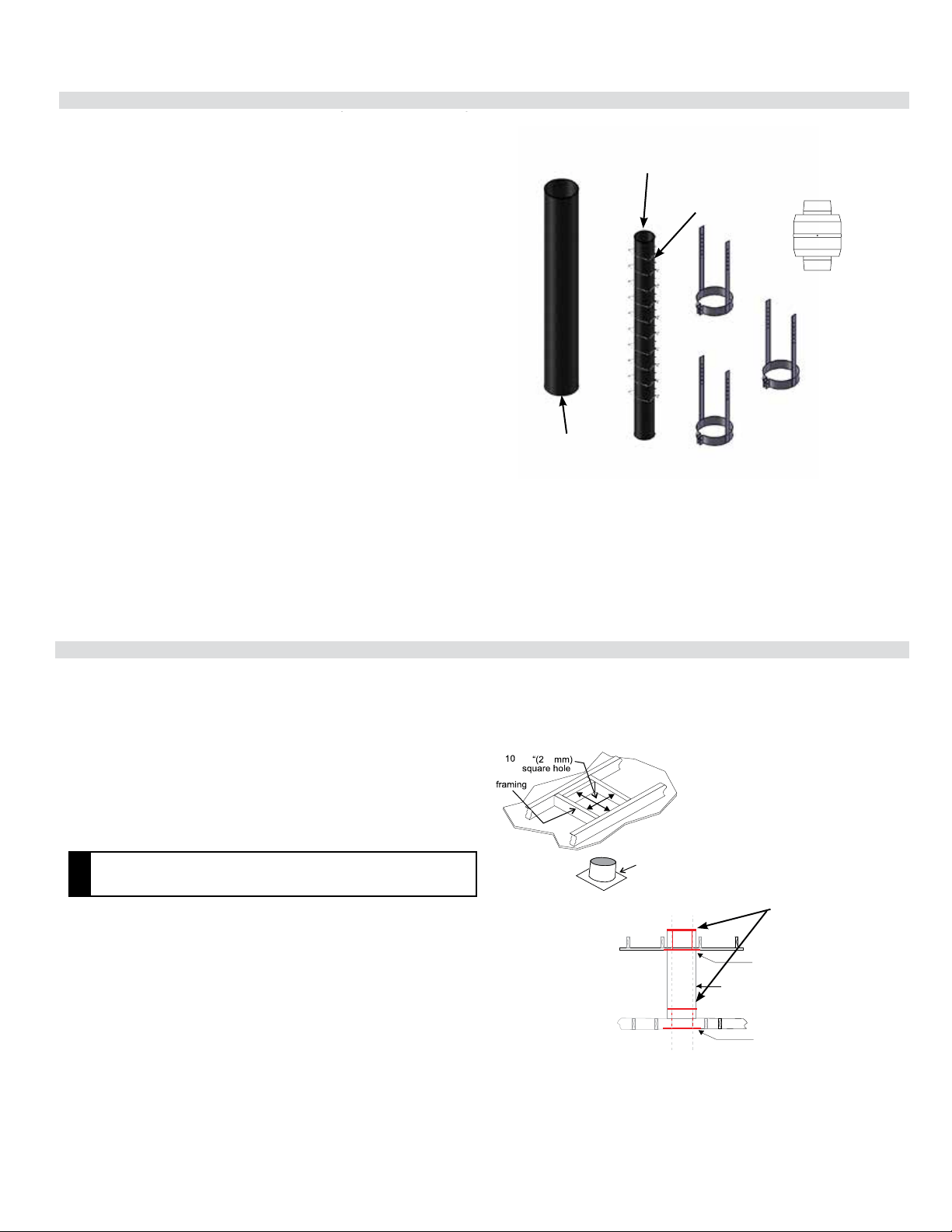
VERTICAL FLUE EXTENSION KIT (PART # 946-756)
20 foot (6.1 m) Flex pipe Extension
(Used in conjunction with the 946-755 Vertical Flex kit and 948-367/P ex
to ex adaptor).
3 wall straps
ex adaptor
4" (102 mm) inner
pipe 20ft. (6.1 m)
6-7/8" (175 mm)
outer ex pipe
20 ft (6.1 m)
10 spring spacers
1
919-698
919-698
06.12.18
06.12.18
60
-1/4
Ceiling firestop
60
-1/4
Ceiling firestop
Diagram 1
Diagram 1
Diagram 1a
Diagram 1a
Enclosure
Ceiling firestop
Flashing
Termination Cap
Storm Collar
Roof support
Ceiling firestop
Enclosure
Ceiling firestop
Flashing
Termination Cap
Storm Collar
Roof support
Ceiling firestop
Firestop spacer to prevent
debris from falling into the ceiling
restop
CEILING FIRESTOP/FIRESTOP SPACER
( PART # 946-757)
Used in conjunction with the 946-755 Vertical Flex Kit and 946-756 Vertical
Flex Extension Kit/Horizontal Power Vent Kit.
CEILING FIRESTOP/FIRESTOP SPACER
( PART # 946-757)
Used in conjunction with the 946-755 Vertical Flex Kit and the 946-756 Verti-
cal Flex Extension Kit/Horizontal Power Vent Kit.
Firestop spacer to prevent
debris from falling into the ceiling
restop
A ceiling restop/restop spacer must be installed when passing through
each oor or ceiling level. To install the ceiling restop/restop spacer in
a at ceiling or oor joist, cut a 10- ¼ inch square hole, frame it as show
in Diagram 1, and install the ceiling restop. Slide the top attic insulation
spacer onto the top of the attic insulation shield/restop (see Diagram 1a).
Secure with 4 screws/nails. If more than one restop is required, these can
be purchased separately.
NOTE
• The ceiling restop/restop spacer may be cut down to size if the
shield is too high for the application.
NOTE
• The ceiling restop/restop spacer may be cut down to size if the
shield is too high for the application.
A ceiling restop/restop spacer must be installed when passing through
each oor or ceiling level. To install the ceiling restop/restop spacer in
a at ceiling or oor joist, cut a 10- ¼ inch square hole, frame it as show
in Diagram 1, and install the ceiling restop. Slide the top attic insulation
spacer onto the top of the attic insulation shield/restop (see Diagram 1a).
Secure with 4 screws/nails. If more than one restop is required, these can
be purchased separately.
1
1
Vertical Flue Extension Kit (Part #946-756)
Ceiling Firestop / Firestop Spacer (Part #946-757)
Loading ...
Loading ...
Loading ...