Loading ...
Loading ...
Loading ...
62 | City Series CC40E-11
installation
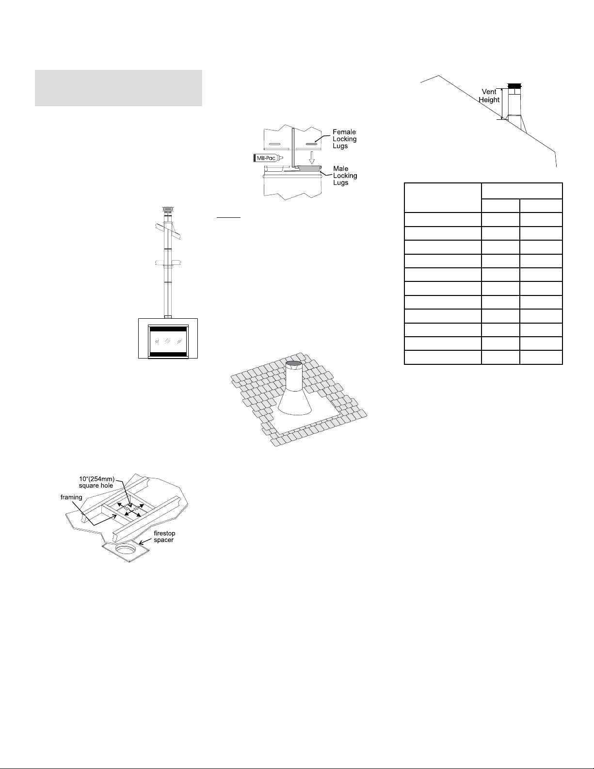
Diagram 4
Diagram 3: The upper half of the ashing is installed
under the roong material and not nailed down
until the chimney is installed. This allows for small
adjustments.
Diagram 2
Diagram 3
Dura Vent Vertical Termination
- 4" x 6-5/8" Venting (Rigid Vent
Systems)
1. Maintain the 1-1/2" clearances (air spaces) to
combustibles when passing through ceilings,
walls, roofs, enclosures, attic rafter, or other
nearby combustible surfaces. Do not pack
air spaces with insulation. Check "Venting"
Sections for the maximum vertical rise of the
venting system and the maximum horizontal
offset limitations.
2. Set the gas appliance in its desired location.
Drop a plumb bob down from
the ceiling to the position of
the appliance flue exit, and
mark the location where the
vent will penetrate the ceiling.
Drill a small hole at this point.
Next, drop a plumb bob from
the roof to the hole previously
drilled in the ceiling, and mark
the spot where the vent will
penetrate the roof.
3. A firestop spacer must
be installed in the floor or
ceiling of every level. To
install the Firestop spacer
in a flat ceiling or wall, cut a
10 inch square hole. Frame the hole as shown
in Diagram 2 and install the firestop.
NOTE: For best results and optimum perfor-
mance with each approved venting system, it is
highly recommended to apply “Mill-Pac” sealant
(supplied) to every inner pipe connection. Failure
to do so may result in drafting or performance
issues not covered under warranty.
4. Assemble the desired lengths of pipe and
elbows. Ensure that all pipes and elbow con-
nections are in the fully twist-locked position
and sealed.
5. Cut a hole in the roof centered on the small
drilled hole placed in the roof in Step 2. The hole
should be of sufficient size to meet the minimum
requirements for clearance to combustibles
of 1-1/2". Slip the flashing under the shingles
(shingles should overlap half the flashing) as
per Diagram 3.
6. Continue to assemble pipe lengths.
Note: If an offset is necessary in the attic
to avoid obstructions, it is important
to support the vent pipe every 3 feet,
to avoid excessive stress on the
elbows, and possible separation.
Wall straps are available for this
purpose.
Galvanized pipe is desirable above the roofline
due to its higher corrosion resistance. Continue
to add pipe sections through the flashing until the
height of the vent cap meets the minimum height
requirements specified in Dia. 4 or local codes.
Note that for steep roof pitches, the vertical
height must be increased. A poor draft, or down
drafting can result from high wind conditions
near big trees or adjoining roof lines, in these
cases, increasing the vent height may solve
the problem.
7. Ensure vent is vertical and secure the base of
the flashing to the roof with roofing rails, slide
storm collar over the pipe section and seal with
a mastic.
8. Install the vertical termination cap by twist-
locking it.
Note: Any closets or storage spaces, which
the vent passes through must be
enclosed.
Diagram 1
Note: All vertical terminations are vented
using 4" x 6-5/8" venting and rigid pipe
adaptor #510-994.
Roof Pitch Minimum Vent Height
Feet Meters
flat to 7/12 2 0.61
over 7/12 to 8/12 2 0.61
over 8/12 to 9/12 2 0.61
over 9/12 to 10/12 2.5 0.76
over 10/12 to 11/12 3.25 0.99
over 11/12 to 12/12 4 1.22
over 12/12 to 14/12 5 1.52
over 14/12 to 16/12 6 1.83
over 16/12 to 18/12 7 2.13
over 18/12 to 20/12 7.5 2.29
over 20/12 to 21/12 8 2.44
Loading ...
Loading ...
Loading ...