City Series
®
Zero Clearance Direct Vent Gas Fireplace
Owners &
Installation Manual
STYLE MODEL
Left Corner CC40LE-NG11 / CC40LE-LP11
Right Corner CC40RE-NG11 / CC40RE-LP11
www.regency-re.com
- Do not store or use gasoline or other flammable vapors and liquids in the vicinity of this or any other
appliance.
- WHAT TO DO IF YOU SMELL GAS
• Do not try to light any appliance.
• Do not touch any electrical switch: do not use any phone in your building.
Leave the building immediately.
• Immediately call your gas supplier from a neighbour's phone. Follow the gas supplier's
instructions.
• If you cannot reach your gas supplier, call the fire department.
- Installation and service must be performed by a qualified installer, service agency or the gas supplier.
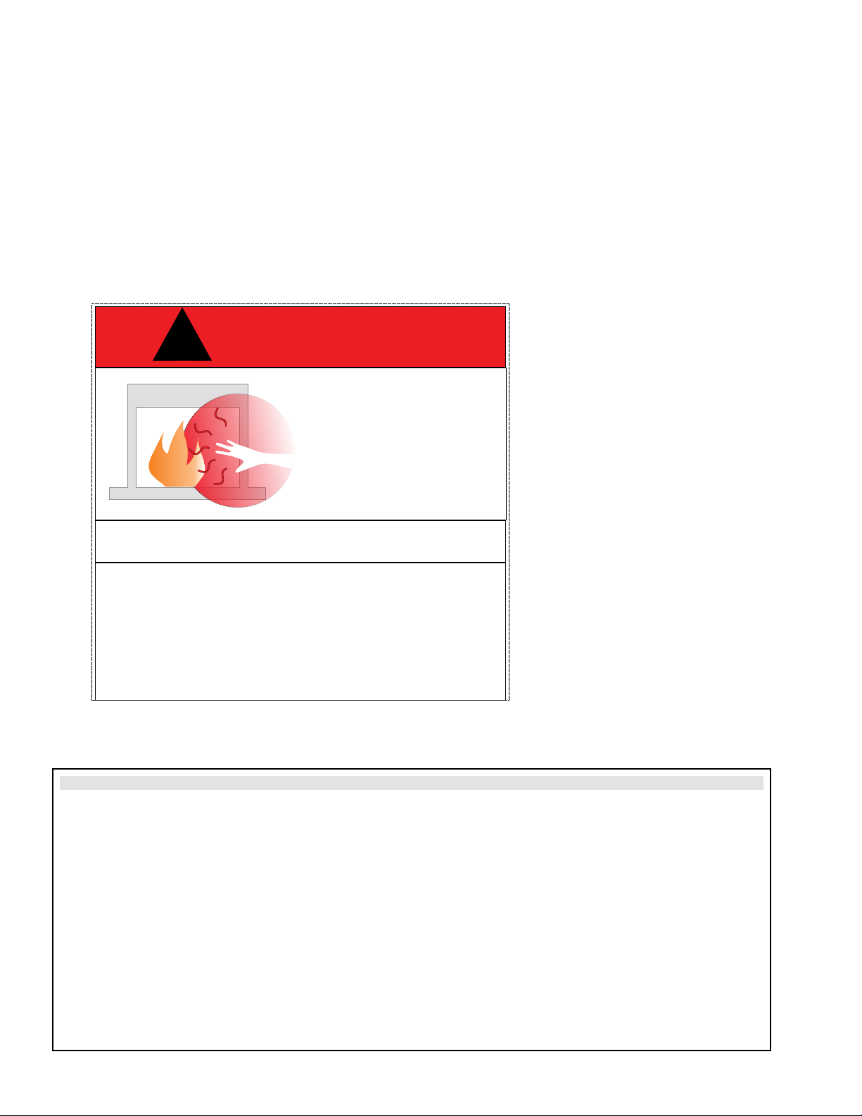
Warning
Fire or explosion Hazard
failure to follow safety warnings exactly could result in serious
injury, death, or property damage.
919-928j
FPI FIREPLACE PRODUCTS INTERNATIONAL LTD. 6988 Venture St., Delta, BC Canada, V4G 1H4
01.31.22
Installer: Please complete the details on the back cover
and leave this manual with the homeowner.
Homeowner: Please keep these instructions for future reference.
Certified to/Certifié pour: CSA 2.17-2017
ANSI Z21.88-2017
CSA 2.33-2017
Tested by:
2 | City Series CC40E-11
To the New Owner:
Congratulations!
You are the owner of a state-of-the-art Gas Fireplace by REGENCY
®
. The City Series are hand crafted appliances and
have been designed to provide you with all the warmth and charm of a wood fireplace at the flick of a switch. The CC40LE
/CC40RE City Series have been approved by Intertek for both safety and efficiency. As it also bears our own mark, it
promises to provide you with economy, comfort and security for many trouble free years to follow. Please take a moment
now to acquaint yourself with these instructions and the many features of your Regency
®
Fireplace.
920-408
4.34.7
Instruction Plate
For a glass-fronted gas appliance where the temperature of the glass
viewing area outside surface exceeds the limits specified in Clause 5.14.4, the following
graphic danger and statements shall be shown on a Class IIIA-2 Permanent Label.
4.34.6
Instruction Plate
Each appliance shall bear a Class IIIB marking with letters on a contrasting background, located
adjacent to the controlling device or in an equally conspicuous position where the instruction can be easily read.
April 22/14: Created draft
Double sided
Material: Synthetic Paper
Size 5.965" W x 5.71" H
Color: As shown in artwork
DANGER
HOT GLASS WILL
CAUSE BURNS
DO NOT TOUCH GLASS
UNTIL COOLED
NEVER ALLOW CHILDREN
TO TOUCH GLASS
A barrier designed to reduce the risk of burns from the hot viewing glass
is provided with this appliance and must be installed for the protection
of children and other at risk individuals.
!
DANGER
!
920-408
CAUTION:
HOT WHILE IN OPERATION. DO NOT TOUCH.
SEVERE BURNS MAY RESULT. KEEP CHILDREN, CLOTHING, FURNITURE,
GASOLINE, AND ANY OTHER LIQUIDS WITH FLAMMABLE VAPOURS AWAY.
KEEP BURNER AND CONTROL COMPARTMENT CLEAN.
SEE INSTALLATION AND OPERATING INSTRUCTIONS ACCOMPANYING
APPLIANCE.
Front
Back
LA SURFACE VITRÉE CHAUDE
PEUT CAUSER DES BRÛLURES.
NE TOUCHEZ PAS À LA
SURFACE VITRÉE NON REFROIDIE.
NE LAISSEZ JAMAIS UN
ENFANT TOUCHER LA SURFACE
VITRÉE.
DANGER
!
L’écran pare-étincelles fourni avec ce foyer réduit le risque de brûlure en cas de
contact accidentel avec la vitre chaude et doit être installé pour la protection des
enfants et des personnes à risque.
920-408-fr
ATTENTION
S'assurer que le brûleur et le compartiment des commandes sont propres.
Voir les instructions d’installation et d’utilisation qui accompagnent
l'appareil.
Risque de brûlures graves.
Ne pas toucher l’appareil lorsqu’il fonctionne.
Ne pas laisser les enfants s’approcher de l’appareil. Garder les
vêtements, les meubles et tout gaz ou liquide inflammable (carburant)
à distance de
l'appareil.
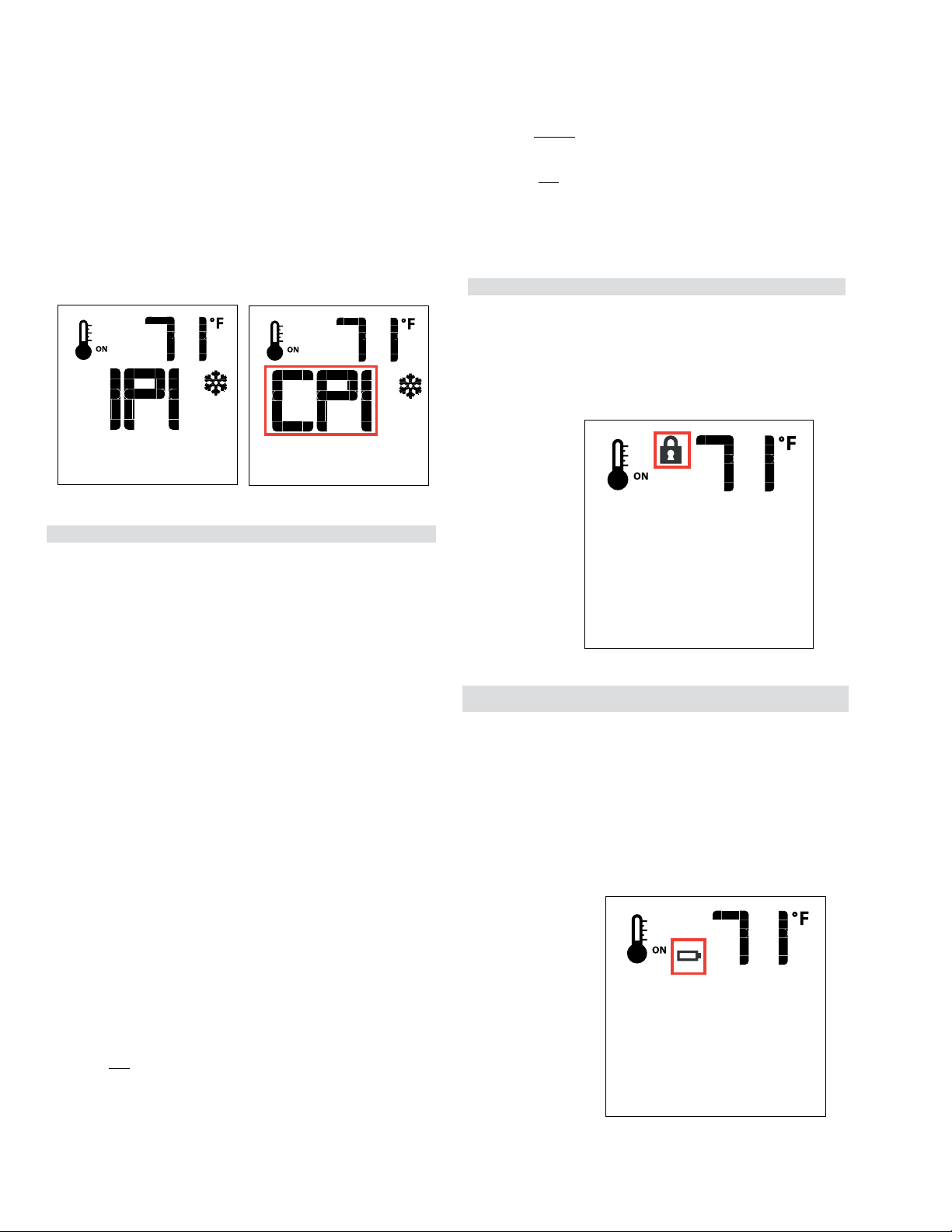
On Demand Pilot Light (seven day safety timer)
Important information if using the appliance in CPI (continuous pilot mode) only
This appliance is a ProFlame 2 system fitted with the “On Demand” Pilot, a safety feature which will shut down the gas valve
completely by extinguishing the pilot light in the event of a continuous full seven days of inactivity.
This only applies if the CPI (continuous pilot) switch is in the “on” position in your remote control transmitter.
Each time the main burner shuts down, manually or through the call from the thermostat, the seven day timer starts again.
The seven day inactivity timer is controlled within the circuit board. Therefore, if in CPI mode and when the pilot light is extinguished
after seven straight days of inactivity, the CPI setting on the remote control transmitter will remain in the “CPI” (continuous pilot)
position. Therefore, all that is required to relight the pilot would be to press the on/off button on the remote control transmitter
from “on” to “off” and back to “on”. Once the pilot has re-established operation will resume as normal. There is no requirement
to do anything with the IPI/CPI mode on the remote control transmitter.
If the unit never goes as long as seven full days without a call for heat, the pilot will remain lit until it is manually shut-off.
If the unit is being operated in IPI (intermittent pilot) mode, neither the above instructions nor the seven day timer will apply.
See the instructions in this manual and on the Lighting Instructions plate on the appliance to light or re-light the pilot.
City Series CC40E-11 | 3
This appliance may be installed in an aftermarket, permanently lo-
cated, manufactured home (USA only) or mobile home, where not
prohibited by local codes.
This appliance is only for use with the type of gas indicated on the
rating plate. This appliance is not convertible fore use with other
gases, unless a certified kit is used.
MANUFACTURED MOBILE HOME REQUIREMENTS
INFORMATION FOR MOBILE/MANUFACTURED HOMES AFTER FIRST SALE
This Regency
®
product has been tested and listed by Warnock Hersey/Intertek as a Direct Vent Wall Furnace to the following standards:
VENTED GAS FIREPLACE HEATERS ANSI Z21.88-2017 / CSA 2.33-2017 and GAS-FIRED APPLIANCES FOR USE AT HIGH ALTITUDES
CSA 2.17-2017.
This Direct Vent System Appliance must be installed in accordance with the manufacturer's installation instructions and the Manufactured
Home Construction and Safety Standard, Title 24 CFR, Part 3280, or the current Standard of Fire Safety Criteria for Manufactured Home
Installations, Sites, and Communities ANSI/NFPA 501A, and with CAN/CSA Z240-MH Mobile Home Standard in Canada.
This appliance installation must comply with the manufacturer's installation instructions and local codes, if any. In the absence of local codes
follow the current National Fuel Gas Code, ANSI Z223.1 and the current National Electrical Code ANSI/NFPA 70 in the U.S.A., and the
current CAN/CGA B149 Gas Installation Code and the current Canadian Electrical Code CSA C22.1 in Canada.
This Regency
®
mobile/manufactured home listed appliance comes factory equipped with four 1/4" diameter holes located near each corner
of the base. Fasten the fireplace in place using screw, inserted through the holes.
This appliance comes equipped with a dedicated #8 Ground Lug for attachment of the ground wire to the steel chassis as applicable to local
codes. See the "Wiring Diagram" section.
The appliance, when installed, must be electrically grounded in accordance with local codes or, in the absence of local codes, with the
National Electrical Code, ANSI/NFPA 70, or the Canadian Electrical Code, CSA C22.1.
This appliance may only be installed in an aftermarket permanently located, manufactured home (U.S.A only) or mobile home, where not
prohibited by local codes.
This appliance can only be used with the type of gas indicated on the rating plate. This appliance is not convertible for use with other gases,
unless a certified kit is used.
Ensure that structural members are not cut or weakened during installation.

4 | City Series CC40E-11
table of contents
Copy of Safety Decal ........................................................................... 5
Decal Location ..................................................................................... 5
Dimensions (Left Corner) .................................................................... 6
Dimensions (Right Corner) .................................................................. 7
Important Message ..........................................................................10
Before You Start ................................................................................. 10
General Safety Information ................................................................ 11
Lighting Procedure ............................................................................ 12
Shutdown Procedure ......................................................................... 12
On Demand Pilot Light ..................................................................... 12
Copy of the Lighting Plate Instructions .............................................. 13
Proflame II Remote Control Operating Instructions ........................... 14
Proflame II Battery Holder Battery Replacement .............................. 18
Outer Safety Glass Panel (Barrier Glass) Installation / Removal....... 19
Inner Glass Panel (Firebox Glass) Installation / Removal ................. 21
Maintenance Instructions................................................................... 23
General Vent Maintenance ................................................................ 23
Log Replacement .............................................................................. 23
Glass Gasket ..................................................................................... 23
Glass ................................................................................................. 23
Glass Replacement ........................................................................... 23
Gas Installation Checklist .................................................................... 8
Locating Your Gas Fireplace .............................................................. 25
Unit Assembly Prior to Installation ..................................................... 25
Installation Checklist .......................................................................... 26
HeatWave Duct System Optional Kit ................................................ 26
Nailing Strips ..................................................................................... 27
Ventilation Openings ..........................................................................28
Chase Enclosure ............................................................................... 29
Clearances ........................................................................................ 30
Mantel Clearances ............................................................................. 33
Framing Dimensions (Left Corner) .................................................... 34
Framing Dimensions (Right Corner) .................................................. 35
Optional Flush Front Chase Vent Installation (Part # 657-991) ......... 36
Optional Front Grill Installation (Part # 656-991) ............................... 39
Optional Side Grill Installation (Part # 656-992) ................................ 39
Wall Board/Drywall Installation .......................................................... 40
Framing and Finishing Inset Installations .......................................... 41
Optional Framing Kit Installation (Part # 656-953) ............................. 42
Building Additional Framing Off of the Framing Kit ............................ 45
TV Recessed into Wall- Typical Installs ............................................. 46
Maximum TV Recess ......................................................................... 46
TV Flush with Hearth ......................................................................... 46
Exterior Vent Termination Locations .................................................. 47
4” x 6-5/8” Rigid Pipe Cross Reference Chart ................................... 48
Wall Mount On/Off Switch and Battery Holder Installation ................ 50
Vent Restrictor Position (Part # 656-017F) ........................................ 51
Horizontal Terminations - Flex Vent 4" x 6-7/8" .................................. 52
Venting Introduction ........................................................................... 53
Venting Arrangement for Horizontal Terminations ............................. 53
Horizontal Terminations - Rigid Pipe 4" x 6-5/8" ................................ 54
Horizontal Terminations - Rigid Pipe 4" x 6-5/8" ................................ 55
Vertical Terminations - Rigid Pipe 4" x 6-5/8" .................................... 56
Venting Arrangement for Vertical Terminations - Straight Vertical
Venting and/or with a Max. of Two (2) 90
o
Elbows
(1 - 90
o
= 2 - 45
o
) ........................................................................... 57
Vertical Terminations - Rigid Pipe 4" x 6-5/8" .................................... 58
Horizontal Termination - 4" x 6-5/8" Venting (Rigid Vent Systems) .... 59
Horizontal Termination - 4" x 6-5/8" Venting (Flex Vent Systems) ...... 60
Dura-Vent Horizontal Terminations .................................................... 61
Dura Vent Vertical Termination - 4" x 6-5/8" Venting (Rigid Vent
Systems) .......................................................................................... 62
Vertical Termination - 4" x 6-7/8" Venting - Vertical Flex Vent Kit
(Part # 946-755) .............................................................................. 63
Vertical Flue Extension Kit (Part #946-756)....................................... 64
Ceiling Firestop / Firestop Spacer (Part #946-757) ........................... 64
CC40LE/CC40RE-11 NG System Data ............................................. 65
CC40LE/CC40RE-11 LP System Data .............................................. 65
High Elevation .................................................................................... 65
Gas Line Installation .......................................................................... 65
Pilot Adjustment ................................................................................. 65
Gas Pipe Pressure Testing ................................................................ 65
885 S.I.T. Valve Description ............................................................... 65
Wiring Diagrams ................................................................................ 66
Inner Glass Panel (Firebox Glass) Installation / Removal ................. 67
Outer Safety Glass Panel (Barrier Glass) Installation / Removal....... 69
LP Conversion Instructions ................................................................ 71
Painted Panel Installation .................................................................. 73
Inner Panels ...................................................................................... 73
Outer Panels ...................................................................................... 73
Glass Panel Installation ..................................................................... 74
Enamel Panel Installation .................................................................. 76
Burner and Firebox Media Options .................................................... 78
Optional Driftwood Log Set Installation ............................................. 79
Optional Birchwood Log Set Installation ............................................ 81
Optional Splitwood Log Set Installation ............................................. 83
Removable Drywall Guides ............................................................... 85
Optional Wall Thermostat .................................................................. 86
Operation Using an Optional Wall Thermostat .................................. 86
Wiring Diagram with Optional Thermostat ......................................... 86
First Fire ............................................................................................ 87
Normal Operating Sounds of Gas Appliances ................................... 87
Aeration Adjustment .......................................................................... 87
Bulb Replacement ............................................................................. 88
Valve Replacement ............................................................................89
Gas Maintenance - Recommended Annual Routine ......................... 90
Main Assembly .................................................................................. 91
Warranty ........................................................................................... 96
Owner's Information
Installer's information
Operating Instructions
Installation
Maintenance
Parts List
City Series CC40E-11 | 5
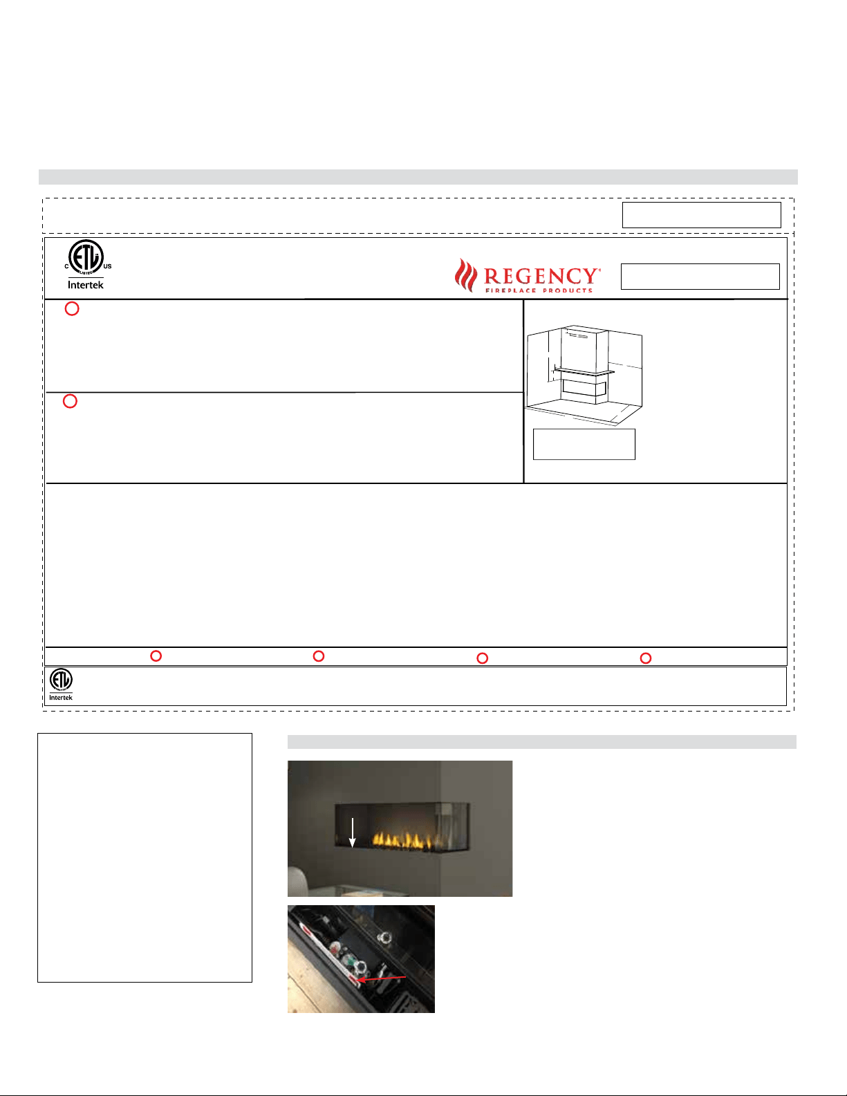
safety decal
This is a copy of the label that accompanies Direct Vent Gas Fireplace. We have printed a copy of the contents here for your review. The safety label is located
on the front inside base of the unit, visible when the outer front panel is removed.
NOTE: Regency
®
units are constantly being improved. Check the label on the unit and if there is a difference, the label on the unit is the correct one.
Copy of Safety Decal
For the State of Massachusetts, installation
and repair must be done by a plumber or
gas fitter licensed in the Commonwealth of
Massachusetts.
For the State of Massachusetts, flexible con-
nectors shall not exceed 36 inches in length.
For the State of Massachusetts, the appli-
ances individual manual shut-off must be a
t-handle type valve.
The State of Massachusetts requires the
installation of a carbon monoxide alarm in
accordance with NFPA 720 and a CO alarm
with battery back up in the same room where
the gas appliance is installed.
Part #: 919-930a
Colour: Black on grey except what is indicated as being printed red.
Size: (File at 100%) 9.2"w x 5.85"h
Material:
Start serial sequence at 930000001
Oct. 15/18: Created draft
Nov. 05/18: New Serial #
Nov. 21/18: Added efficiencies as per R/D
Jan 23/19: Rev A - Remodeled decal + added ETL logo at the bottom
DO NOT REMOVE THIS LABEL / NE PAS ENLEVER CETTE ÉTIQUETTE
483
483
DOOR SEAL: Please
check that the door is
properly sealed
FPI Fireplace Products International Ltd. Delta, BC, Canada
Minimum Clearances to Combustibles /
Dégagements minimaux par rapport aux matériaux combustibles
Serial No./ No de série
MAY BE INSTALLED IN MANUFACTURED (MOBILE) HOMES AFTER FIRST SALE.
Listed/Nom: VENTED GAS FIREPLACE / FOYER AU GAZ À ÉVACUATION
Certified to/Certifi : é ANSI Z21.88-2017 • CSA-2.33-2017
CSA 2.17-2017
Electrical supply / Alimentation électrique 115VAC, 1.5 A, 60Hz.
Made in Canada/ Fabriqué au Canada
Duplicate S/N
(See Instruction Manual for
detailed instructions)
(Voir manuel pour plus de détails)
APPAREIL FONCTIONNANT AU GAZ PROPANE
Modèle
CC40LE-LP11/CC40RE-LP11
PROPANE GAS: Model: CC40LE-LP11/CC40RE-LP11
NATURAL GAS: Model: CC40LE-NG11/CC40RE-NG11
Minimum supply pressure
Manifold pressure - High
Manifold pressure - Low
Orifice size
Maximum input
Minimum input
Altitude
APPAREIL FONCTIONNANT AU GAZ NATUREL
Modèle
CC40LE-NG11/CC40RE-NG11
5.0 " WC/C.E. (1.25 kPa)
3.8 " WC/C.E. (0.94 kPa)
1.1" WC/C.E. (0.27 kPa)
# 42 DMS
28,500 Btu/h (8.33 kW)
15,500 Btu/h (4.54 kW)
0-4500 ft/pi (0-1372 m)
11" WC (2.73 kpa)
10.5 " WC/C.E. (2.62 kPa)
2.9" WC/C.E. (0.72 kPa)
# 53 DMS
28,500 Btu/h (8.35kW)
15,500 Btu/h (4.54 kW)
0-4500 ft/pi (0-1372 m)
Minimum supply pressure
Manifold pressure - High
Manifold pressure - Low
Orifice size
Maximum input
Minimum input
Altitude
Side Walls / Murs latéraux
A 36” (914 mm)
Ceiling / Plafond
B 37-1/2” (953 mm)
Min. Mantel Height/Hteur Min Manteau
C 9" (229 mm)
Max. Mantel Depth/Profondeur Max
Manteau
D 12” (305 mm)
Alcove Width/Largeur Alcôve
E 84" (1524 mm)
Alcove Depth/Profondeur Alcôve
F 36" (2134 mm)
This appliance must be installed in accordance with local codes, if any; if none, follow the National Fuel Gas Code, ANSI Z223.1, or Natural Gas and Propane Installation Code, CSA B149.1.
This appliance must be installed in accordance with the Standard CAN/CSA Z240 MH, Mobile Housing, in Canada, or with the Manufactured Home Construction and Safety Standard, Title 24 CFR, Part 3280, in the
United States, or when such a standard is not applicable, ANSI/NCSBCS A225.1/NFPA 501A, Manufactured Home Installations Standard or ANSI A119.2 ou NFPA 501C Standard for Recreational Vehicles
This appliance is only for use with the type(s) of gas indicated on the rating plate and may be installed in an aftermarket, permanently located, manufactured home (USA only) or mobile home, where not prohibited by
local codes. See owner's manual for details. This appliance is supplied with a conversion kit.
L'appareil doit être installé conformément aux codes et règlements locaux, ou, en l'absence de tels règlements, selon les codes d'installation National Fuel Gas Code ANSI Z223.1, ou CSA-B149.1 Natural Gas and
Propane Installation Code en vigueur.
L'appareil doit être installé conformément à la norme CAN/CSA-Z240, Série MM, Maisons mobiles ou CAN/CSA-Z240 VC, Véhicules de camping, ou la norme 24 CFR Part 3280, Manufactured Home Construction
and Safety Standard. Si ces normes ne sont pas applicables, veuillez vous référer à la norme ANSI/NCSBCS A225.1/NFPA 501A, Manufactured Home Installations Standard, ou ANSI A119.2 ou NFPA 501C
Standard for Recreational Vehicles.
Cet appareil doit être utilisé uniquement avec les types de gaz indiqués sur la plaque signalétique et peut être installé dans une maison préfabriquée (É.-U. seulement) ou mobile installée à demeure si les règlements
For Use Only with Barrier CC40LE - Left Corner (Part # 940-485/P,940-440/P) & CC40RE Right Corner (Part # 940-485/P,940-439/P) Follow installation instructions.
Utiliser uniquement avec l’écran CC40LE -Coin gauche (n°940-485/P,940-440/P) & CC40RE - Coin droit (n°940-485/P,940-439/P) . Suivre les instructions d'installation.
Pression d'alimentation minimale
Pression de sortie (manifold) - Haute
Pression de sortie (manifold) -
Basse
Taille de l’orifice
D bit calorifique maximal é
D bit calorifique minimalé
Altitude
Pression d'alimentation minimale
Pression de sortie (manifold) - Haute
Pression de sortie (manifold) - Basse
Taille de l’orifice
D bit calorifique maximalé
D bit calorifique minimalé
Altitude
VENTED GAS FIREPLACE - NOT FOR USE WITH SOLID FUELS.
NE PAS UTILISER AVEC UN COMBUSTIBLE SOLIDE. FOYER AU GAZ À ÉVACUATION -
Part No. 946-556 Heatwave Kit may be used. La trousse Heatwave (pièce n°946-556) peut être utilisée.
Model/Modèle :
CC40LE-NG11
CC40LE-LP11 CC40RE-NG11 CC40RE-LP11
FOR USE WITH GLASS DOORS CERTIFIED WITH THE APPLIANCE ONLY À UTILISER AVEC LES PORTES VITRÉES HOMOLOGUÉES POUR L'APPAREIL
C #: 4001172
Refer to Intertek's Directory of Building Products for detailed information.
Pour plus de détails , se reporter au Répertoire des produits de construction de Intertek.
J
B
C
D
H
A
E
F
919-930a
CSA P.4.1 Fireplace Efficiency (FE) /Efficacité énergétique des foyers (EEF) CSA P.4.1
Natural Gas / Gaz naturel 55.23%
Propane Gas / Gaz propane 56.06%
CANADIAN ENERGY
PERFORMANCE
VERIFIED
RENDEMENT
ÉNERGÉTIQUE
VÉRIFIÉ
EP5011169
Decal Location
Remove barrier glass from unit (refer to manual) lift
out the outer liner base glass once the glass has been
removed the rating plate will be attached to a small black
chain as seen below.
DO NOT REMOVE DECAL FROM UNIT

6 | City Series CC40E-11
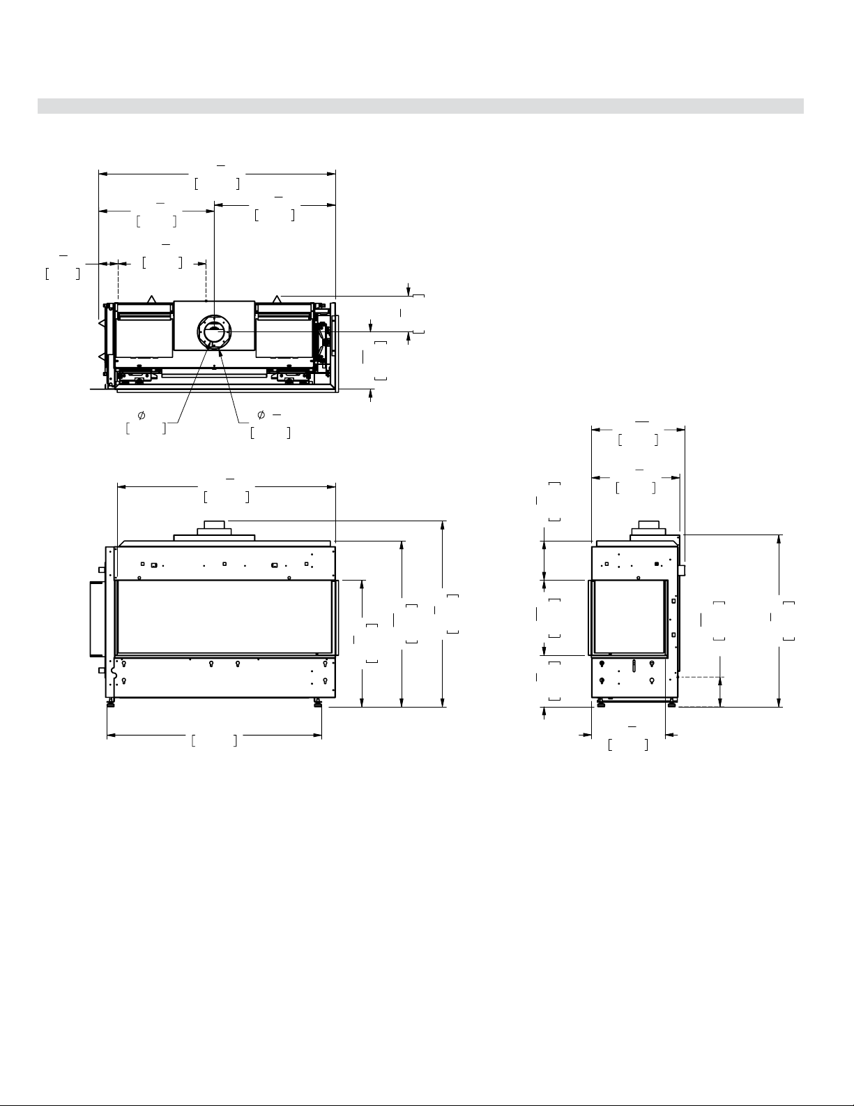
dimensions
25
1
4
"
643mm
33
3
16
"
842mm
37
1
8
"
943mm
42
7
8
"
1089mm
43
5
8
"
1109mm
10
1
4
"
261mm
15
1
16
"
382mm
7
7
8
"
200mm
14
3
4
"
375mm
34
3
8
"
873mm
18
11
16
"
475mm
17
5
8
"
449mm
3
15
16
"
101mm
GAS INPUT
AREA HEIGHT
6
3
4
"
172mm
4"
102mm
48"
1219mm
23
1
8
"
587mm
24
1
4
"
616mm
47
3
8
"
1203mm
3
13
16
"
97mm
17
5
8
"
448mm
GAS LINE
INPUT AREA
Note: Height Dimension may vary depending on the height of the leveling legs.
Dimensions (Left Corner)
Dimensions will appear as (inches)" / (metric)mm
throughout this manual. The inches are rounded to the
nearest 1/16" when converted, when greater accuracy
is required, use the metric dimensions.
Note: These units are non-load bearing.
ALL PICTURES / DIAGRAMS SHOWN THROUGHOUT THIS MANUAL ARE FOR ILLUSTRATION PURPOSES ONLY.
ACTUAL PRODUCT MAY VARY DUE TO PRODUCT ENHANCEMENTS.
Note: Electrical connection on left hand side of the appliance.
A metal receptacle box is supplied/installed with the appliance to make all 120 volt electrical connections.
City Series CC40E-11 | 7
dimensions
43"
1091mm
25
1
4
"
643mm
33
3
16
"
842mm
37
1
8
"
943mm
43
5
8
"
1108mm
7
7
8
"
200mm
15
1
16
"
382mm
10
1
4
"
262mm
14
3
4
"
374mm
34
3
8
"
873mm
17
5
8
"
448mm
18
11
16
"
475mm
5
15
16
"
151mm
GAS INPUT
AREA HEIGHT
6
3
4
"
172mm
4"
102mm
11
7
16
"
290mm
7
1
4
"
184mm
23
1
8
"
587mm
24
1
4
"
616mm
47
3
8
"
1203mm
3
7
8
"
98mm
17
5
8
"
448mm
GAS LINE
INPUT AREA
Dimensions (Right Corner)
Note: Height Dimension may vary depending on the height of the leveling legs.
Dimensions will appear as (inches)" / (metric) mm throughout this manual. The inches are rounded to the
nearest 1/16" when converted, when greater accuracy is required, use the metric dimensions.
Note: These units are non-load bearing.
8 | City Series CC40E-11
dimensions
05/18/21
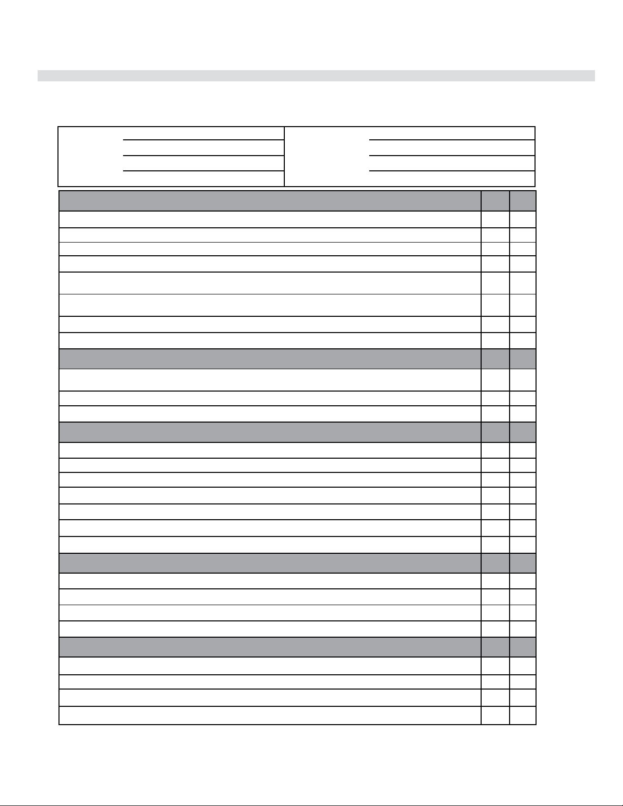
1
REGENCY GAS INSTALLATION CHECKLIST
Customer: Date Installed:
Install Address: Location of Fireplace:
Serial No: Installer:
Model No:
Site Requirements YES NO
If applicable, are the insulation, vapour barrier, and drywall present if installed on an outside wall or chase?
Does the area have a solid continuous base to support the unit?
Will the area accommodate the size of the applliance and all clearances?
Are the gas and electrical roughed into the area where the unit is being installed?
In City & Grandview series cool wall applications, is the chase enclosure sealed to prevent heat from escaping? All hot air
from the unit must exit via the mandatory ventilation openings.
In City & Grandview applications, Is the chase enclosure vented with the mandatory heat ventilation openings? See manual
for details.
If applicable, is the masonry/factory built freplace in its original condition with no modifications?
If applicable, have the hearth requirements been met?
Unit Setup YES NO
If applicable, are the standoffs and top nailing flange extensions installed and at the correct depth to accommodate finishing
material? See manual for details.
If applicable, is the fireplace level and secured, meeting framing clearances? See manual for details.
If applicable, is the unit converted to top or rear vent per manual instructions, and the insulation discarded?
Venting YES NO
Are the venting components approved for the unit installed?
Does the venting configuration comply with venting diagrams?
Is venting installed and secured, and are clearances for the vent pipe and termination cap maintained?
If applicable, was a 1/4" rise maintained for every foot of horizontal run?
Was the termination installed and sealed?
Is the direct vent termination at the highest point in the vent assembly?
If applicable, are both chimney liners continuous from flue collars to termination?
Electrical and Wiring YES NO
Is the appliance connected to the household's 110/120v per local codes? Check local codes for receptacle placement.
Were the connections in the fireplace tested with a circuit tester?
Is the appliance properly grounded?
If applicable, is the supplied electrical/gang box affixed to the wall to facilitate the mounting of the receiver/battery box ?
Gas YES NO
Does the supply pressure meet the requirements shown on the rating plate?
Was a conversion performed?
Was a leak check performed and manifold pressures verified?
Is the shut-off valve installed and easily accessible to the customer?
This general checklist does not contain all pertinent installation details or specifics and does not supersede the guidelines in this manual. Your
Regency dealer/installer should use it in conjunction with manual instructions. Please follow all local codes and jurisdictions in authority.
Gas Installation Checklist
City Series CC40E-11 | 9
installation
05/18/21
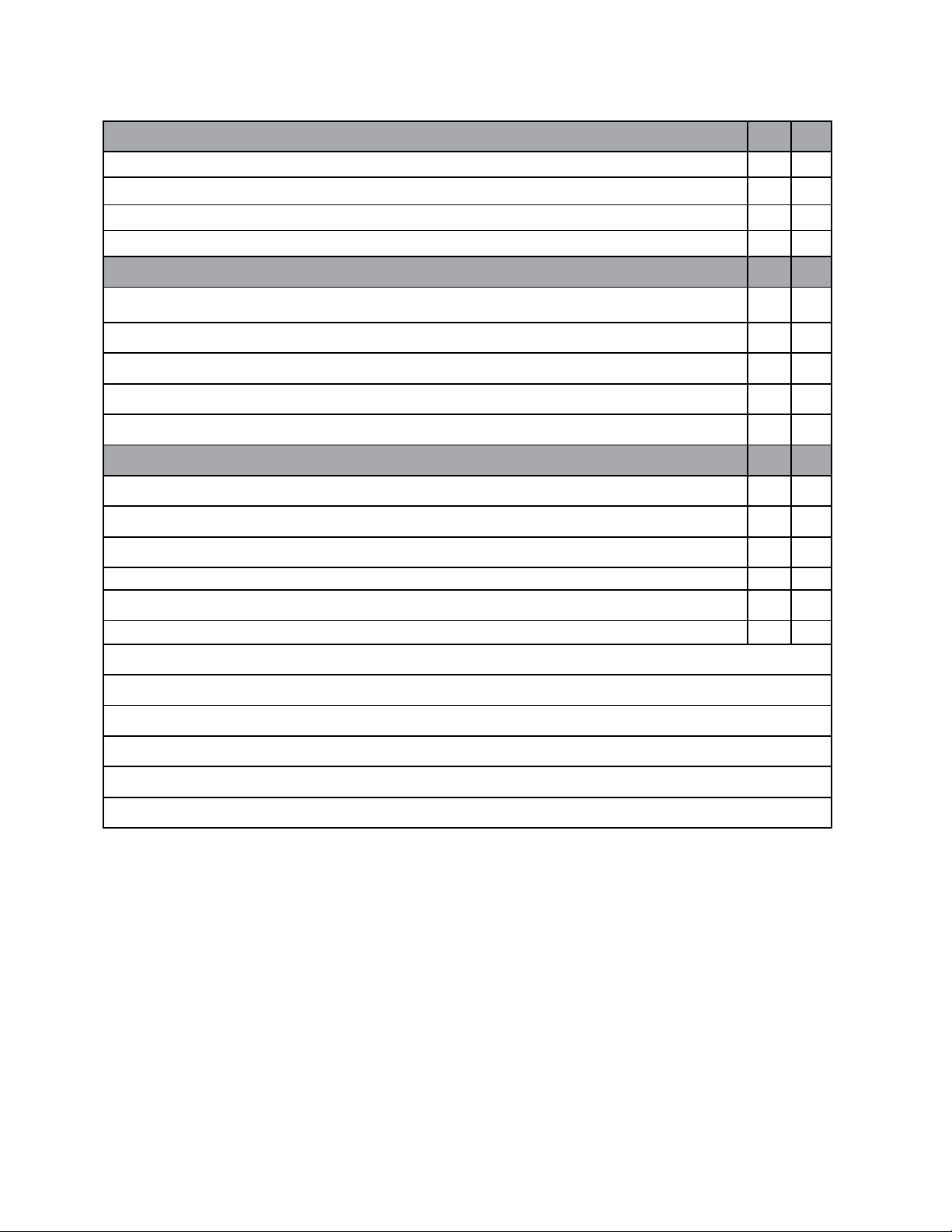
2
REGENCY GAS INSTALLATION CHECKLIST
Finishing YES NO
If applicable, is only noncombustible material installed in the noncombustible areas?
Do clearances meet installation and manual requirements?
Do the mantels and/or projections comply with the installation manual?
If applicable, was the solid fuel fireplace warning plate installed?
Appliance Media Setup YES NO
Do commands from the remote or wall switch light the pilot and main burner?
Are the burner media/log set, glass door, and screen installed per instructions in the manual?
Was the air shutter on the proper setting after running the unit for 20 minutes?
If applicable, were the surround and trims installed according to the manual?
Was the operation of the fan, lights (if installed), and flame modulation checked?
Customer Tutorial and Presentation YES NO
Is the customer confident operating the new gas appliance and aware of all the features on the remote?
Confirm that the rating and lighting plates are attached to the appliance. Do not remove.
Was the customer informed of the location of the rating and lighting plates?
Was accessing unit controls in a power outage explained to the customer?
Are the model and serial numbers and the date of installation of the unit written in the manual and on the checklist?
Were the warranty and unit registration reviewed with the customer?
Comments:
10 | City Series CC40E-11
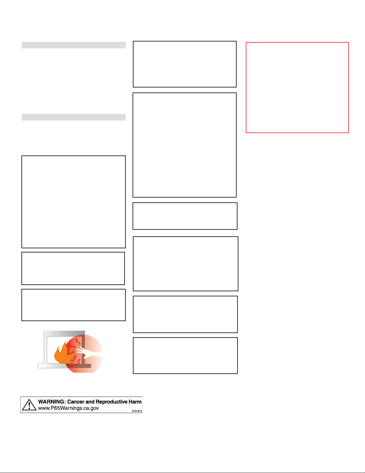
owner's information
CLOTHING OR OTHER FLAMMABLE
MATERIAL SHOULD NOT BE PLACED
ON OR NEAR THE APPLIANCE.
CHILDREN AND ADULTS SHOULD BE
ALERTED TO THE HAZARDS OF HIGH
SURFACE TEMPERATURES, ESPE-
CIALLY THE FIREPLACE GLASS, AND
SHOULD STAY AWAY TO AVOID BURNS
OR CLOTHING IGNITION.
INSTALLATION AND REPAIR SHOULD
BE DONE BY AN AUTHORIZED
SERVICE PERSON. THE APPLIANCE
SHOULD BE INSPECTED BEFORE
USE AND AT LEAST ANNUALLY BY A
PROFESSIONAL SERVICE PERSON.
MORE FREQUENT CLEANING MAY
BE REQUIRED DUE TO EXCESSIVE
LINT FROM CARPETING, BEDDING
MATERIAL, ETC. IT IS IMPERATIVE THAT
CONTROL COMPARTMENTS, BURNERS
AND CIRCULATING AIR PASSAGEWAYS
OF THE APPLIANCE BE KEPT CLEAN.
DUE TO HIGH TEMPERATURES, THE
APPLIANCE SHOULD BE LOCATED
OUT OF TRAFFIC AND AWAY FROM
FURNITURE AND DRAPERIES.
WARNING: FAILURE TO INSTALL THIS
APPLIANCE CORRECTLY WILL VOID
YOUR WARRANTY AND MAY CAUSE A
SERIOUS HOUSE FIRE.
YOUNG CHILDREN SHOULD BE CARE-
FULLY SUPERVISED WHEN THEY ARE
IN THE SAME AREA AS THE APPLI-
ANCE. TODDLERS, YOUNG CHILDREN
AND OTHERS MAY BE SUSCEPTIBLE
TO ACCIDENTAL CONTACT BURNS. A
PHYSICAL BARRIERS IS RECOMMEND-
ED IF THERE ARE AT RISK INDIVIDUAL
IN THE HOUSE. TO RESTRICT ACCESS
TO A FIREPLACE OR STOVE, INSTALL
AN ADJUSTABLE SAFETY GATE TO
KEEP TODDLERS, YOUNG CHILDREN
AND OTHER AT RISK INDIVIDUALS OUT
OF THE ROOM AND AWAY FROM HOT
SURFACES.
Important Message
SAVE THESE INSTRUCTIONS
City Series Direct Vent Fireplaces must be
installed in accordance with these instructions.
Carefully read all the instructions in this manual
first. Consult the "authority having jurisdiction" to
determine the need for a permit prior to starting the
installation. It is the responsibility of the installer to
ensure this fireplace is installed in compliance with
manufacturer's instructions and all applicable codes.
Before You Start
Safe installation and operation of this appliance
requires common sense, however, we are required
by the Canadian Safety Standards and ANSI
Standards to make you aware of the following:
ANY SAFETY SCREEN, GUARD, OR
BARRIER REMOVED FOR SERVICING
THE APPLIANCE, MUST BE REPLACED
PRIOR T O OPERATING THE APPLIANCE.
IF THE BARRIER BECOMES DAMAGED,
THE BARRIER SHALL BE REPLACED
WITH THE MANUFACTURER'S
BARRIER FOR THIS APPLIANCE.
A BARRIER DESIGNED TO REDUCE
THE RISK OF BURNS FROM THE HOT
VIEWING GLASS IS PROVIDED WITH
THIS APPLIANCE AND SHALL BE
INSTALLED FOR THE PROTECTION
OF CHILDREN AND OTHER AT-RISK
INDIVIDUALS
WE RECOMMEND REMOVING THE
GLASS WITH THE GLASS VACUUM
HOLDERS SUPPLIED BY THE MANU-
FACTURER. LOWER THE GLASS TO
REST IN A SAFE PLACE. THIS IS TO
PREVENT DAMAGE TO THE GLASS
EDGES. EXTRA CARE MUST BE TAKEN
WHEN REMOVING/INSTALLING THE
GLASS. BREAKAGE OR DAMAGE TO
THE EDGE OF THE GLASS WHICH
OCCURS AS A RESULT OF CARELESS
HANDLING WILL NOT BE COVERED
UNDER WARRANTY.

City Series CC40E-11 | 11
owner's information
General Safety Information
1. The appliance installation must conform with
local codes or, in the absence of local codes,
with the current Canadian or National Gas
Codes, CAN1-B149 or ANSI Z223.1 Installation
Codes.
2. See general construction and assembly
instructions. The appliance and vent should be
enclosed.
3. This appliance must be connected to the
specified vent and termination cap to the outside
of the building envelope. Never vent to another
room or inside a building. Make sure that the
vent is fitted as per Venting instructions.
4. Inspect the venting system annually for blockage
and any signs of deterioration.
5. Venting terminals shall not be recessed into a
wall or siding.
6. Any safety glass removed for servicing must
be replaced prior to operating the appliance.
7. To prevent injury, do not allow anyone who is
unfamiliar with the operation to use the fireplace.
8. Wear gloves and safety glasses for protection
while doing required maintenance.
9. Be aware of electrical wiring locations in walls
and ceilings when cutting holes for termination.
10. Under no circumstances should this appliance
be modified. Parts that have to be removed for
servicing should be replaced prior to operating
this appliance.
11. Installation and any repairs to this appliance
should be done by a qualified service person.
A professional service person should be called
to inspect this appliance annually. Make it a
practice to have all of your gas appliances
checked annually.
12. Do not slam shut or strike the glass door.
13. Under no circumstances should any solid fuels
(wood, paper, cardboard, coal, etc.) be used in
this appliance.
14. The appliance area must be kept clear and
free of combustible materials, (gases and other
flammable vapours and liquids).

12 | City Series CC40E-11
owner's information
* Not offered on all models.
IMPORTANT: The remote control system supplied with this appliance has
several options for starting/operating the appliance using the battery holder
and ON/OFF key on the hand held transmitter.
Prior to operating this appliance, please read the remote control operating
instructions (packaged with remote control) to understand how to operate
this remote control system.
1. Ensure the battery holder switch is in the Remote position and / or wall
mounted battery holder (if equipped) is in the <REMOTE> position.
2. Press and release the ON/OFF button on the remote handheld transmitter
(see Diagram 1). An audible beep should be heard from the receiver. If
not using the remote, the unit can also be turned on by sliding the battery
holder switch to the <ON> position (if equipped).
Note: The first try for ignition will last approximately 60 seconds. If there is no
flame ignition (rectification) the board will stop sparking for approximately
35 seconds. After wait time , the board will start second try for ignition by
sparking for approximately 60 seconds . If there is still no positive ignition
the board will go into lock out.
The system will need to be reset as follows:
a) Turn the system off by pressing the ON/OFF button on the remote.
b) Wait 5 minutes then repeat from step 2.
Shutdown Procedure
1. Press the ON/OFF button on the remote
2. If service is to be performed, you must disconnect power and shut off gas
to the unit.
Remote (Part # 911-175) Shown in
Manual Mode on High
3. After approximately 4 seconds the spark ignition system will spark for 60
seconds to light the pilot.
4. The unit will turn on.
Lighting Procedure
Continuous Pilot/Intermittent Pilot (CPI/IPI) selection
See remote control instructions for details.
*
*
*
On Demand Pilot Light
Important:
This appliance has a timer built into the pilot light. The timer starts when the
main burner has been shut-off via the remote control, thermostat, or ON/
OFF switch. Once the burner is shut off, the timer is set for 7 days. If there
is no call for heat within a 7 day period -- the pilot is designed to extinguish.
See instructions in this manual for lighting pilot.
ON/OFF
Button
Diagram 1
City Series CC40E-11 | 13
owner's information
Copy of the Lighting Plate Instructions
919-649
Part #: 919-649
Colours: Black on Grey, except for parts indicated as being Red.
Punch out .25" hole top right corner where indicated.
Size: 100%
w- 6.52"
h- 11.13"
Apr 05/16: Created decal
Apr. 26/16: Added Fr. Headers/warnings
w- 6.5"
h- 11"
A) This appliance is equipped with an ignition device which automatically lights the pilot.
Do not try to light the pilot by hand.
B) BEFORE OPERATING smell all around the appliance area for gas. Be sure to smell next to the oor
because some gas is heavier than air and will settle on the oor.
WHAT TO DO IF YOU SMELL GAS
- Do not try to light any appliance.
- Do not touch any electric switch, do not use any phone in your building.
- Immediately call your gas supplier from a neighbours phone. Follow the gas supplier’s instructions.
- If you cannot reach your gas supplier, call the re department.
C) Do not use this appliance if any part has been under water. Immediately call a qualied service
technician to inspect the appliance and replace any part of the control system and any
gas control which has been underwater.
A) Cet appareil est muni d’un dispositif d’allumage qui allume automatiquement la veilleuse.
Ne tentez pas d’allumer la veilleuse manuellement.
B) AVANT LA MISE EN MARCHE, reniez tout autour de l’appareil pour déceler une odeur de gaz. Reniez au niveau du plancher, car certains gaz
sont plus lourds que l’air et peuvent s’accumuler au niveau du sol.
QUE FAIRE SI VOUS SENTEZ UNE ODEUR DE GAZ :
• Ne tentez pas d’allumer l’appareil
• Ne touchez à aucun interrupteur; n'utilisez pas de téléphones se trouvant dans le bâtiment.
• Appelez immédiatement votre fournisseur de gaz depuis un téléphone extérieur. Suivez les instructions du fournisseur.
• Si vous ne pouvez pas rejoindre le fournisseur, appelez le service incendie.
C) N’utilisez pas cet appareil s’il a été plongé dans l’eau, même partiellement. Faites inspecter l’appareil par un technicien qualié et remplacez
tout élément du système de contrôle ou de commande qui a été plongé dans l’eau.
DO NOT REMOVE THIS INSTRUCTION PLATE
NE PAS ENLEVER CETTE ÉTIQUETTE D’INSTRUCTIONS
TO TURN OFF GAS APPLIANCE / POUR ÉTEINDRE UN APPAREIL AU GAZ
This appliance must be installed in accordance with local codes, if any; if none, follow the National Fuel Gas Code, ANSI Z223.1/NFPA 54,
or Natural Gas and Propane Installation Codes, CSA B149.1.
Cet appareil doit être installé conformément aux codes locaux, s’il y a lieu. En l’absence de tels codes, suivre le National Fuel Gas Code,
ANSI Z223.1/NFPA 54, ou les Natural Gas and Propane Installation Codes, CSA B149.1.
CAUTION: Hot while in operation. Do not touch. Severe burns may result. Due to high surface temperatures keep
children, clothing and furniture, gasoline and other liquids having ammable vapors away. Keep burner and control
compartment clean. See installation and operating instructions accompanying appliance.
ATTENTION : Surfaces chaudes lorsque l’appareil est en marche. Ne pas toucher. Risque de brûlures graves. En raison
des températures élevées, les enfants, les vêtements et le mobilier, le carburant et tout autre liquide aux vapeurs
inammables doivent être tenus éloignés de l’appareil. Nettoyer régulièrement le brûleur et le compartiment des
commandes. Voir les consignes d’installation et d’utilisation fournies avec l’appareil.
WARNING: If you do not follow these instructions exactly, a fire or explosion may result causing property damage,
personal injury or loss of life. Improper installation, adjustment, alteration, service or maintenance can cause injury or
property damage. Refer to the owner’s information manual provided with this appliance. For assistance or additional
information consult a qualified installer, service agency or gas supplier.
AVERTISSEMENT : Quiconque ne respecte pas scrupuleusement les instructions de la présente notice risque de déclencher
un incendie ou une explosion pouvant entraîner des dégâts matériels ou des blessures pouvant être mortelles.
Tout défaut d'installation, de réglage, de modication, de service ou d'entretien peut entraîner des blessures ou des dom-
mages matériels. Reportez-vous au manuel d'utilisation fourni avec cet équipement. Pour obtenir de l'aide ou des informa-
tions complémentaires, consulter un installateur ou un service d'entretien qualié, ou le fournisseur de gaz.
1) Ensure the Main switch is in the ON position and/or the wall mounted battery holder (if equipped) is in the <REMOTE> position.
2) Press and release the ON/OFF button on the remote handheld transmitter. An audible beep should be heard from the receiver. If not
using the remote, the unit can also be turned on by sliding the battery holder switch to the <ON> position (if equipped).
3) After approximately 4 seconds the spark ignition system will spark for 60 seconds to light the main burner.
4) The unit will turn on.
Note: The rst attempt to ignition will last approximately 60 seconds. If there is no ame ignition (rectication) the board will stop spark-
ing for approximately 35 seconds. After this wait time, the board will start a second try for ignition by sparking for approximately 60
seconds. If there is still no positive ignition after the second attempt the board will go into lock out.
The system will need to be reset as follows (after going into lock out mode):
a) Wait 5 minutes - turn the system o by pressing the ON/OFF button on the remote.
b) After approximately 2 seconds press the ON/OFF button again.
c) Unit will repeat step 2.
1) S’assurer que le commutateur principal est en position ON et/ou que le bloc-piles mural (le cas échéant) est en position <REMOTE>.
2) Appuyer sur la touche ON/OFF de la télécommande puis relâcher. Un bip sonore retentira depuis le récepteur. Si vous n'utilisez pas
la télécommande, l'appareil peut également être allumé en faisant glisser le commutateur du bloc-piles sur la position <ON> (le cas
échéant).
3) Après environ 4 secondes, le système d'allumage produira une étincelle pendant 60 secondes pour allumer le brûleur principal.
4) L'appareil s’allumera.
Remarque : Au premier allumage, le système tente d’allumer les ammes pendant 60 secondes. Si l’essai est infructueux, le système
fera une pause de 35 secondes. C’est ce qu'on appelle l'étape de rectication. Ce délai écoulé, le système tente à nouveau d'allumer les
ammes en produisant des étincelles pendant 60 secondes. Si les ammes ne s’allument toujours pas, le système se met en mode ver-
rouillage.
Il faut alors le réinitialiser en suivant les étapes ci-dessous (pour le déverrouiller) :
a) Attendre 5 minutes et éteindre l’appareil en appuyant sur la touche ON/OFF de la télécommande.
b) Attendre 2 secondes et appuyer encore une fois sur la touche ON/OFF.
c) L'appareil répètera l'étape 2.
1) Press the ON/OFF button on the remote.
2) If service is to be performed–you must disconnect power and shut off gas to the unit.
1)
Appuyer sur la touche ON/OFF de la télécommande.
2) Lors de l'entretien de l'appareil, vous devez débrancher l'alimentation électrique et couper le gaz alimentant l'appareil.
LIGHTING INSTRUCTIONS / CONSIGNES D’ALLUMAGE
FOR YOUR SAFETY READ BEFORE LIGHTING
POUR VOTRE SÉCURITÉ – À LIRE AVANT LA MISE EN MARCHE
14 | City Series CC40E-11
owner's information
Proflame II Remote Control Operating Instructions
WARNING: THE TRANSMITTER AND RECEIVER ARE RADIO
FREQUENCY DEVICES. PLACING THE RECEIVER IN OR
NEAR METAL MAY SEVERELY REDUCE THE SIGNAL RANGE.
The Proflame 2 Transmitter provides for controlling the following hearth
appliance functions:
1. Main Burner On/Off
2. Main Burner flame modulation (6 levels)
3. Choice of standing or intermittent pilot (CPI/IPI)
4. Thermostat and Smart thermostat functions
5. Accent light modulation (6 levels)**
6. Split flow valve**
7. Comfort Fan speed modulation (6 levels)**
** This feature is not available on all models.
IMPORTANT:The Proflame Transmitter 2 is an integrated part of the
Proflame 2 System, which consists of these elements:
• Proflame 2 Transmitter, to be used in conjunction with:
• Integrated Fireplaces Control (Proflame 2 IFC)
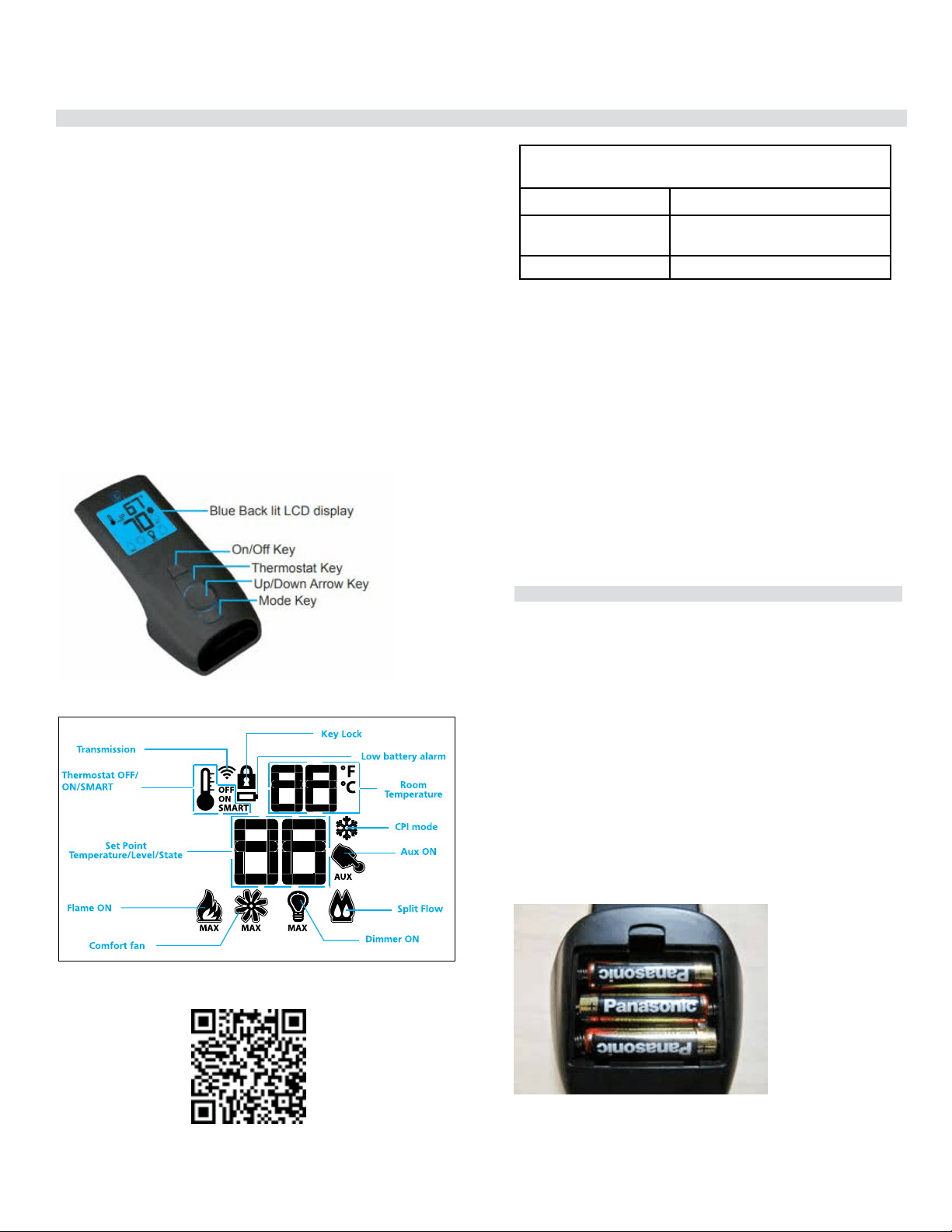
The Proflame Transmitter (Part # 911-175) uses a streamline design
with a simple button layout and informative LCD display (Fig. 1). A Mode
Key is provided to index between the features and a Thermostat Key is
used to turn on/off or index through Thermostat functions (Fig. 1 & 2).
Additionally, a Key Lock feature is provided (Fig. 22).
Figure 1: Proflame Transmitter
Figure 2: Transmitter LCD Display
TECHNICAL DATA
REMOTE CONTROL
Supply Voltage 4.5V (three 1.5V AAA batteries)
Ambient temperature
ratings
0 - 50
o
C (32 - 122
o
F)
Radio Frequency 315 MHZ
ATTENTION!
- Turn “OFF” the main gas supply of the appliance during installation or
maintenance of the Receiver device.
- Turn “OFF” main gas supply to the appliance prior to removing or rein-
serting the batteries.
- In case of remote control malfunction, turn off the IFC device using the
"ON/OFF" main switch.
- For installation / maintenance, switch off the IFC device removing main
power supply plug.
Operating Procedure
Pairing the remote control to remote receiver/battery
holder (if required)
Power the receiver. Press the ''PRG'' button located on the top right
hand corner of receiver/battery holder, see the receiver instruction (*).
The Receiver will “beep” three (3) times to indicate that it is ready to
synchronize with a Transmitter. Install the 3 AAA type batteries in the
Transmitter battery bay, located on the base of the Transmitter. (Fig.
3) With the batteries already installed in the Transmitter, push the On
button. The Receiver will “beep” four times to indicate the Transmitter’s
command is accepted and sets to the particular code of that Transmitter.
The system is now initialized.
(*) The receiver may be independent or integral to the IFC hearth appliance
control module. The receiver instruction may not be independent when
part of the IFC.
Figure 3: Battery Compartment
City Series CC40E-11 | 15
owner's information
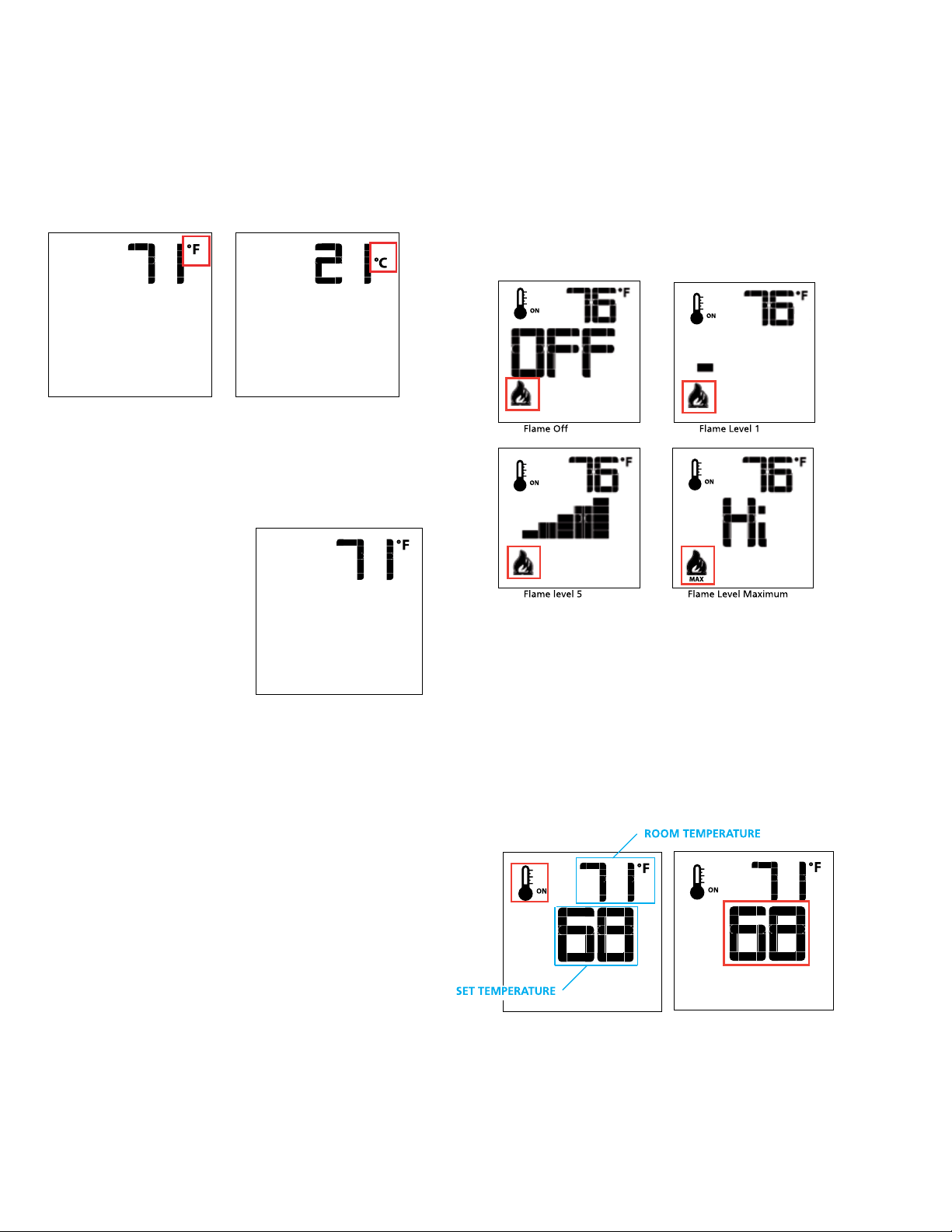
Figure 4: Remote Control dis-
play in Farenheit.
Temperature indication Display
With the system in the "OFF" position, press the Thermostat Key and
the Mode Key at the same time. Look at the LCD screen on the transmit-
ter to verify that a C or F is visible to the right of the room temperature
display (Figures 4 & 5).
Figure 5: Remote Control dis-
play in Celsius.
Turn on the Appliance
With the system OFF, press the ON/
OFF Key on the Transmitter. The
Transmitter display will show some
other active Icons on the screen. At the
same time the Receiver will activate
the appliance. A single “beep” from
the Receiver will confirm reception of
the command.
Figure 6: Remote Control
display
Remote-Flame Control
The Proflame has six (6) flame levels. With the system on, and the flame
level at the maximum in the appliance, pressing the Down Arrow Key
once will reduce the flame height by one step until the flame is turned off.
The Up Arrow Key will increase the flame height each time it is pressed.
If the Up Arrow Key is pressed while the system is on but the flame is off,
the flame will come on in the high position. ( Fig. 7 & 8 ) A single “beep”
will confirm reception of the command.
Fig. 7
Fig. 8
Room Thermostat (Transmitter Operation)
The Remote Control can operate as a room thermostat. The thermostat
can be set to a desired temperature to control the comfort level in a room.
To activate this function, press the Thermostat Key (Fig. 1). The LCD
display on the Transmitter will change to show that the room thermostat
is “ON” and the set temperature is now displayed (Fig. 9). To adjust the
set temperature, press the Up or Down Arrow Keys until the desired set
temperature is displayed on the LCD screen of the Transmitter.
Figure 9 Figure 10
Turn off the Appliance
With the system ON, press the ON/OFF Key on the Transmitter. The
Transmitter LCD display will only show the room temperature (Fig. 6).
At the same time the Receiver will turn off the appliance. A single “beep”
from the Receiver confirms reception of the command.
16 | City Series CC40E-11
owner's information
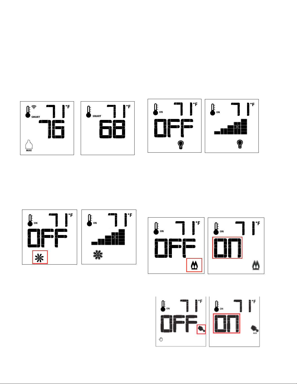
Smart Thermostat (Transmitter Operation)
The Smart Thermostat function adjusts the flame height in accordance
to the difference between the set point temperature and the actual room
temperatures. As the room temperature gets closer to the set point the
Smart Function will modulate the flame down.
To activate this function, press the Thermostat Key (Fig. 1) until the word
"SMART" appears to the right of the temperature bulb graphic (Fig. 11).
To adjust the set temperature, press the Up or Down Arrow Keys until
the desired set temperature is displayed on the LCD screen of the
Transmitter (Fig. 12).
Note. When Smart Thermostat is activated, manual flame height adjust-
ment is disabled.
Figure 12Figure 11: Smart Flame Function
Fan Speed Control**
If the appliance is equipped with a hot air circulating fan, the speed of
the fan can be controlled by the Proflame system. The fan speed can be
adjusted through six (6) speeds. To activate this function use the Mode Key
(Fig.1) to index to the fan control icon (Fig. 13). Use the Up/Down Arrow
Keys (Fig.1) to turn on, off or adjust the fan speed (Fig. 14). A single “beep”
will confirm reception of the command.
Remote Auxiliary Relay Control**
The auxiliary function controls the AUX relay outlet. To activate this func-
tion use the Mode Key (Fig. 1) to index to the AUX icon (Fig. 19 & 20).
Pressing the Up Arrow Key will activate the outlet. Pressing the Down
Arrow Key will turn the outlet off. A single “beep” will confirm the recep-
tion of the command.
Figure 13 Figure 14
Remote dimmer control (Bottom Ember Light)**
The auxiliary function controls the AUX power outlet by the dimmable
light control. To activate this function use the Mode Key (Fig. 1) to index
to the AUX icon (Fig. 15 & 16).
The intensity of the output can be adjusted through six (6) levels. Use
the Up/Down Arrow Keys (Fig.1) adjust the output level (Fig. 16). A single
“beep” will confirm reception of the command.
Note: This function is available only with the IFC Control Module.
Figure 15 Figure 16
Split Flow control**
The secondary burner is controlled by the split Flow. To activate this
function use the Mode Key (Fig. 1) to index to the SPLIT FLOW mode
icon (Fig. 17 & 18).
Pressing the Up Arrow Key will activate the secondary burner. Pressing
the Down Arrow Key will turn the secondary burner off. A single “beep”
will confirm the reception of the command.
Figure 17
Figure 19
Figure 18
Figure 20
City Series CC40E-11 | 17
owner's information
Continuous Pilot/Intermittent Pilot (CPI/IPI) selection
Note: Power vent models do not have a Continuous
Pilot option.
With the system in "OFF" position press the Mode Key (Fig. 1) to index
to the CPI mode icon (Fig. 21 & 22).
Pressing the Up Arrow Key will activate the Continuous Pilot Ignition
mode (CPI). Pressing the Down Arrow Key will return to IPI. A single
“beep” will confirm the reception of the command.
Figure 21 Figure 22
key lock
This function will lock the keys to avoid unsupervised operation.
To activate this function, press the MODE and UP Keys at the same
time (Fig. 23).
To de-activate this function, press the MODE and UP Keys at the
same time.
Figure 23
low battery power detection
Transmitter
The life span of the remote control batteries depends on various factors:
quality of the batteries used, the number of ignitions of the appliance,
the number of changes to the room thermostat set point, etc.
When the Transmitter batteries are low, a Battery Icon will appear on the
LCD display of the Transmitter (Fig. 24) before all battery power is lost.
When the batteries are replaced this Icon will disappear.
Figure 24
CPI/IPI Switch
This appliance comes equipped with a CPI/IPI switch. The functions of
both the CPI/IPI switch are as follows:
Continuous pilot (CPI) - A pilot that when in operation, is intended to
remain continuously ignited until it is manually interrupted.
Intermittent pilot (IPI) - A pilot that is automatically ignited when an ap-
pliance is called on to operate and which remains continuously ignited
during each period of main burner operation. The pilot is automatically
extinguished when each main burner operating cycle is completed. The
mode of the fireplace is easily changed from an intermittent pilot ignition
system (IPI) to a continuous pilot ignition system (CPI) by using remote
control as noted above.
The benefits of having as CPI are as follows:
- Keeps venting primed for trouble free start-up under colder weather
conditions or inversions.
- Keeps the unit glass warm, which decreases the amount of condensa-
tion on start-up
-Provides owners with flexibility to choose a traditional continuous pilot.
The primary benefit of having the IPI function is a significant savings on
fuel as the pilot will only run when there is a call for heat.
Thermostat Icon: If the thermostat icon is not present on the remote
transmitter, follow instructions noted below:
1. Remove one battery from the remote.
2. Press and hold down the Thermostat button on the remote.
3. Reinstall the battery(removed in Step 1) while still holding down
thermostat button.
4. If you see "Set" the thermostat option is now enabled. If you see "Clr"
the thermostat option is now disabled.
5. Repeat the procedure if the "Set" or "Clr" to remove or add the option
back to the remote did not appear.
Enable all other functions if not present on the remote transmitter, follow
instructions noted below:
1. Remove one battery from remote.
2. Press and hold both the ON/OFF and MODE button at the same time .
3. Reinstall battery removed in Step 1 while holding both buttons—keep
holding buttons, then release the MODE button only.
4. The screen will show either "Clr" or "Set" as the first option available
is to disable or enable a mode.
5. "Clr" will remove a mode—use the up or down arrow while holding
down ON/OFF and MODE (mode icon will disappear once removed).
6. Use the "MODE" button to move to the next function.
7. "Set" will add a mode —use the up or down arrow while holding
down ON/OFF and MODE (mode icon will appear when added).
8. Use the "MODE" button to move to the next function.
Note: You should never program out the fan (if installed) or CPI/IPI
mode on the remote.
18 | City Series CC40E-11
owner's information
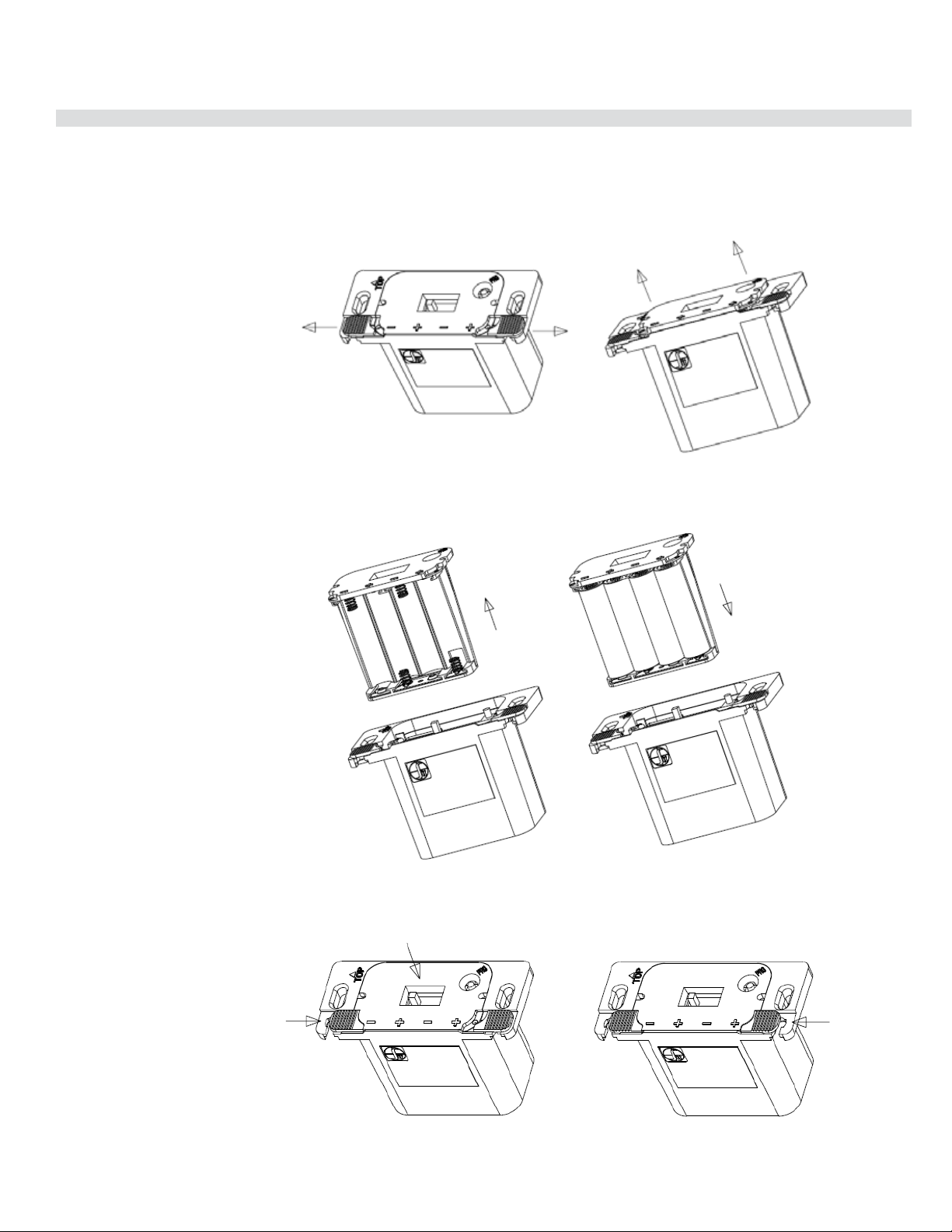
1 | 1
Battery Holder Battery Replacement & Battery Back up if 120 volt power is lost
witihin home
How to replace/add the batteries on battery holder (Proflame 2).
Note : If a wall switch cover plate is installed, first remove cover plate by removing 2 small phillips head screws
STEP 1
STEP 2
STEP 3
STEP 4 Reinstall wall cover plate with 2 Phillips head screws.
Replace 4 x AA batteries and insert the battery
compartment back into remote receiver/battery holder
Move both the left/right slides
as shown below.
The battery compartment
will be pushed out slightly,
to allow to easily extract it
Extract the battery
compartment from the remote
receiver/battery holder
Close the right slide
Keeping the battery compartment
pressed in, close the left slide
Proflame II Battery Holder Battery Replacement & Battery Pack up if 120 Volt Power is lost
City Series CC40E-11 | 19
owner's information
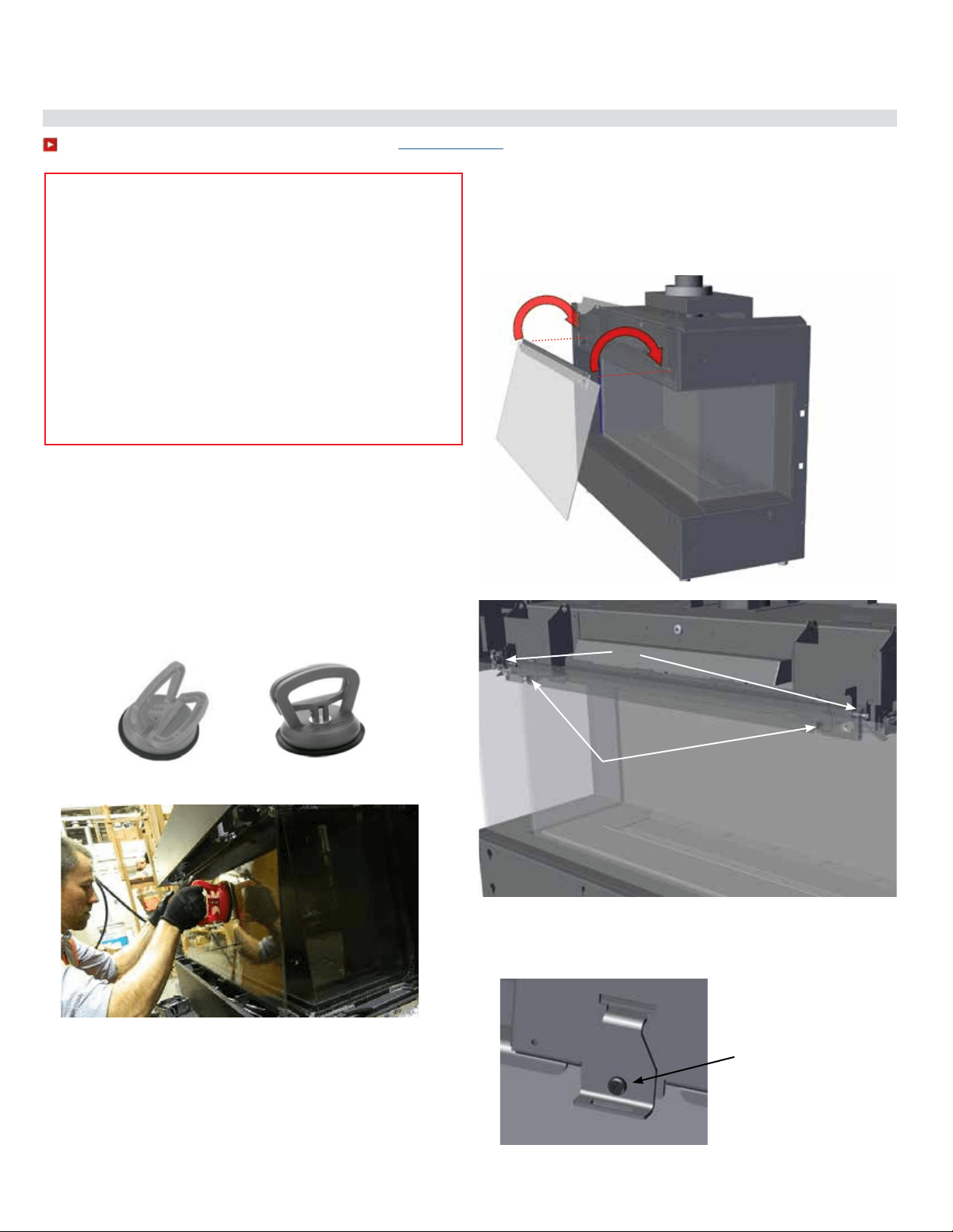
To watch the safety barrier glass installation video click here http://bit.ly/2ryq0c0
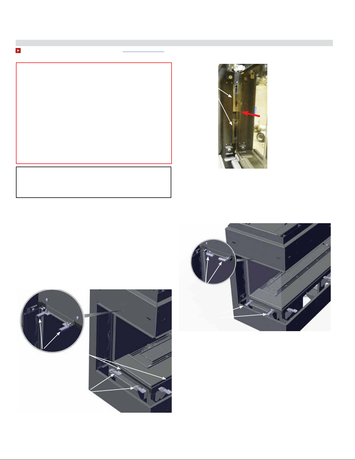
Outer Safety Glass Panel (Barrier Glass) Installation / Removal
Outer glass safety panels to be installed during the initial installation after the
unit is in the final position.
Note: The outer safety panels come with plastic corners to protect these against
damage. These should be kept in place until such time the outer safety panels
are installed. Ensure these are removed prior to operating the appliance. Keep
the plastic corners in a safe place if ever removing the outer panels for servicing.
1. Carefully remove glass safety panels from packaging.
3. Tilt the top of the glass panel inward and lift up and underneath
the upper front panel of the outside frame. Hook the glass panel
onto the pins and also onto the two angle adjustment brackets lo-
cated on the frame in two locations as shown in the diagram below.
Note: The front frame upper panel is shown as transparent to better
illustrate the install (this area is not visible when installing glass).
Press glass vacuum clamp (part # 948-078/pair) in open position firmly onto
surface of glass. Bring handles together to close.
Open
Closed
NOTE: Inner glass panel shown in image - depicting proper handling
of glass.
WARNING: GLASS HANDLING
We recommend using the glass vacuum holders supplied by the manufac-
turer. Lower the glass to rest in a safe place, this is to prevent damage to the
glass edges. Extra care must be taken when removing/installing the glass.
Breakage or damage to the edge of the glass which occurs as a result of
careless handling will not be covered under warranty.
• We recommend handling the glass with supplied vacuum
clamps
• When removing glass–prepare a soft, scratch resistant
surface to place the glass
• Never clean or remove hot glass
Note: The suction cups may leave a round film on the glass
when used. Ensure that the glass is cleaned using a fireplace
glass cleaner prior to operating the appliance.
Note: If the outer safety glass panels do not sit at 90º and angle too far
inward or outward, remove the glass panel and adjust the screw of
the panel angle bracket. Turn the panel angle bracket screw in 1/4
increments—reinstall panel to check.
Angle adjustment brackets
Pins on body of unit
Panel angle bracket—to
adjust, turn screw:
Clockwise = bring panel in
Counter clockwise= bring
panel out
2. Using the supplied vacuum clamps, lift the large front glass panel and
position it front and centre by manoeuvering up and underneath the front
of the unit frame.
Note: safety glass panels must be installed to operate fireplace
20 | City Series CC40E-11
owner's information
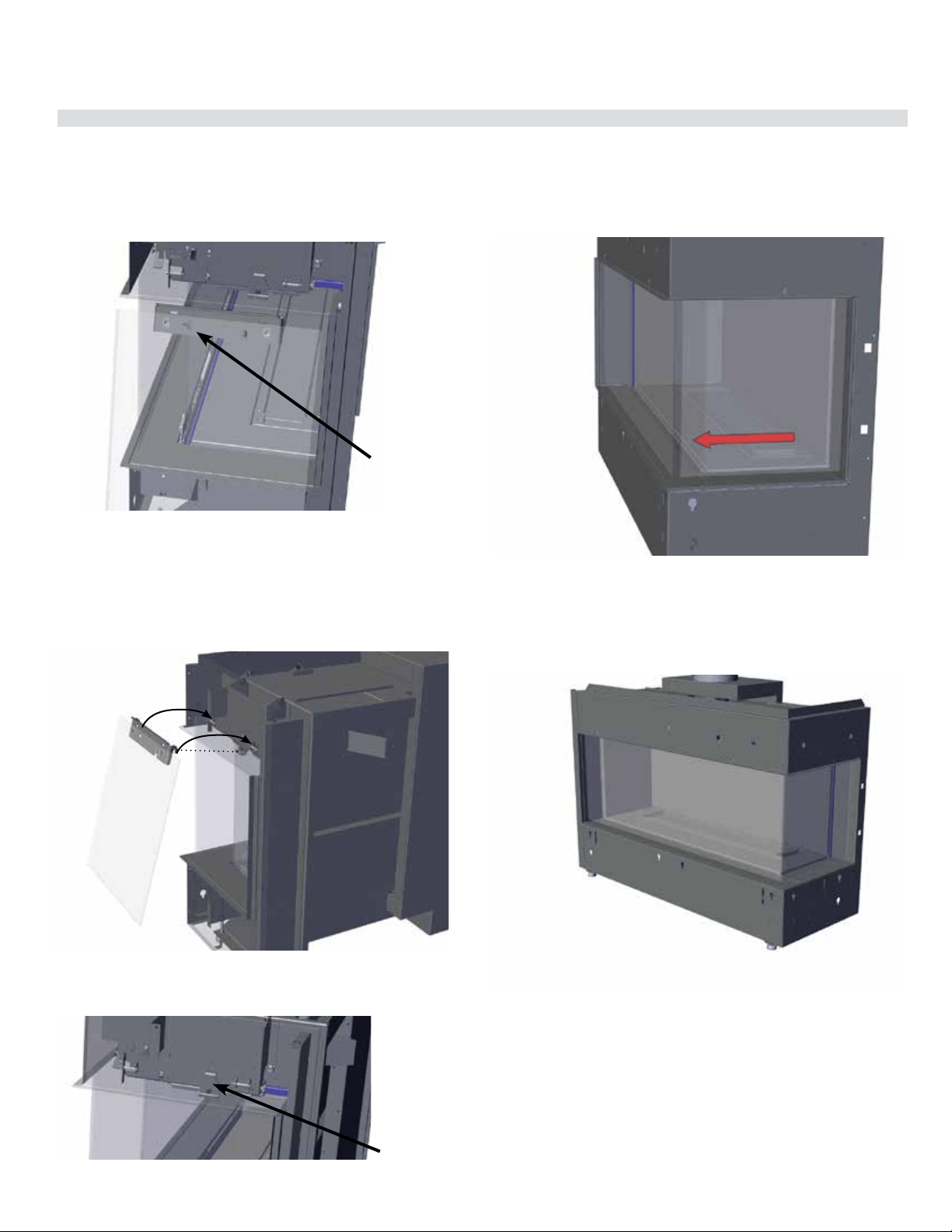
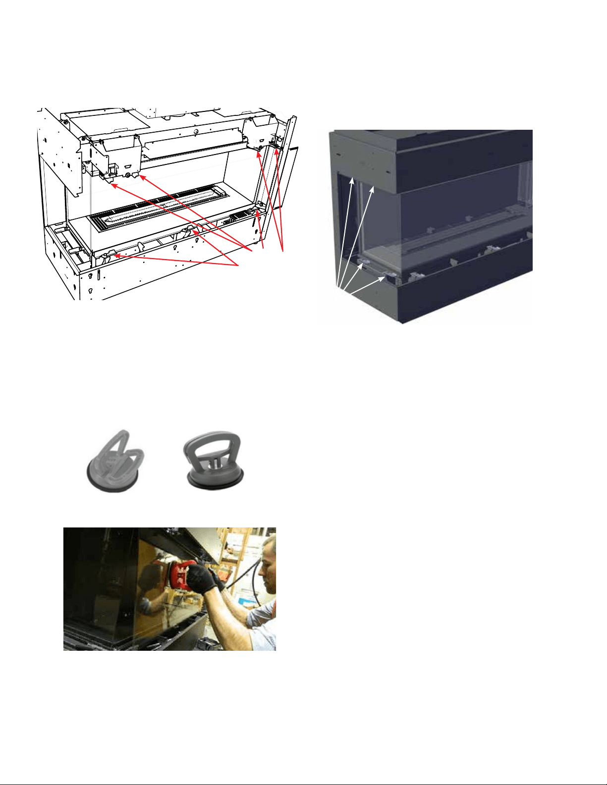
Outer Safety Glass Panel (Barrier Glass) Installation / Removal
Note: safety glass panels must be installed to operate fireplace.
Note: If the outer safety glass side panels angle too far inward or outward,
remove the side glass panel and adjust on the panel angle bracket,
see details on previous page.
5. Lift up the side panel with the supplied glass clamps (see procedure on
previous page). Tilt the side of the glass panel inward and lift up and under-
neath the upper side panel and hook the 2 outer hooks on to the pins, there
is also a panel angle adjustment bracket for the third hook.
Note: The side frame upper panel is shown as transparent to better
illustrate the install (this area is not visible when installing glass).
4. For 3 sided and corner units only:
With front panel installed, proceed to install the side panel(s).
Identify the left and right side panels before installing. Facing the front of
the unit, the right panel will show an arrow pointing to the front of the unit
as shown in the diagram below.
Note: After the side panel has been adjusted so it is installed at 90º to the
unit and not flaring in or out, check to ensure there is no gap between
the front and side panel. If there is a gap as shown below, slide the side
panel to adjust the position and close the gap.
Direction arrow on side
panel bracket, should
point toward front of
unit
6. Repeat Steps 4 and 5 to install the opposite side panel.
7. Reverse Steps to remove all panels.
Note: When removing panels, we recommend using the supplied glass clamps.
Panel angle bracket
City Series CC40E-11 | 21
owner's information
Inner Glass Panel (Firebox Glass) Installation / Removal
1. Remove outer safety glass panels if previously installed–see instructions
in this manual.
2. CC40LE/CC40RE Single sided & CC40LE/CC40RE 3 Sided Units—Re-
move outer panels installed in units - see panel removal section in this manual.
Single sided units–proceed to Step 5.
3. Ensure all 4 clamps on each side are open to allow clearance for the glass.
Lift up side panel using supplied vacuum clamp and tilt inward and upward
positioning into a top channel and lowering gently into the lower glass chan-
nel–slide the side glass panel firmly towards the back wall until the springs
at the back wall are compressed.
4. With the springs compressed, close the 2 clamps at the bottom and 2 clamps
at the top, by turning inward, to secure the glass in position. For the 3 sided
unit, repeat on the opposite side.
Top clamps in
open position
Bottom side clamps in
open position
CC40LE/CC40RE shown
CC40LE/CC40RE shown
Bottom
channel
Top clamps in
closed position
Bottom clamps in
closed position
Push side glass
panel firmly
to back wall
until springs are
compressed—
then close
clamps.
Important:
Prior to installing the inner glass, ensure that there is no media present in
the bottom channel as this can cause damage to the glass. Remove any
media from bottom channel prior to installing the glass.
WARNING: GLASS HANDLING
We recommend using the glass vacuum holders supplied by the manufac-
turer. Lower the glass to rest in a safe place, this is to prevent damage to the
glass edges. Extra care must be taken when removing/installing the glass.
Breakage or damage to the edge of the glass which occurs as a result of
careless handling will not be covered under warranty.
• We recommend handling the glass with supplied vacuum
clamps
• When removing glass–prepare a soft, scratch resistant
surface to place the glass
• Never clean or remove hot glass
Note: The suction cups may leave a round film on the glass
when used. Ensure that the glass is cleaned using a fireplace
glass cleaner prior to operating the appliance.
Note: glass panels must be installed to operate fireplace
To watch the firebox installation video click here http://bit.ly/2qfQwST
22 | City Series CC40E-11
owner's information
Note: Ensure that the front glass is centered and evenly spaced with side glass
(3 sided unit) - open to release glass clamps to remove from surface of glass.
CC40LE shown
Handle front panel with supplied vacuum clamps
tooltip
Open clamps
prior to plac-
ing front glass
panel
5. Ensure all 7 front clamps are in the open position to allow clearance for
the glass.
6. Lift up the front panel using the supplied vacuum clamps and position into
the lower front channel–ensure the front panel is accurately centered—with
the front panel in position—secure in place by closing the 3 lower clamps
and 4 upper clamps.
Open clamps to
release pressure on
the springs
Press glass vacuum clamps (part # 948-078/pair) in open position firmly onto
surface of glass. Bring handles together to close.
Open
Closed
7. Return to the side panel(s), and release the upper and lower clamps. The
springs will release and push the glass side panel forward slightly—this will
create a seal between the front and side panels. When the junction between
the front and side glass panels is sealed, close the clamps to secure the
side panel(s) in place.
8. To remove the glass panels—always remove the side panel(s) (for 3 sided
units) before removing the front panel.
9. Reverse steps to remove glass.

City Series CC40E-11 | 23
owner's information
and exterior portions of the system being
exposed to cold weather.
4. Inspect joints, to verify that no pipe sections or
fittings have been disturbed, and consequently
loosened. Also check mechanical supports
such as Wall Straps, or plumbers' tape for
rigidity.
Log Replacement
The unit should never be used with broken logs.
Turn off the gas valve and allow the unit to cool
before opening door and carefully remove the logs.
(The pilot light generates enough heat to burn
someone.) If for any reason a log should need
replacement, you must use the proper replacement
log. The position of these logs must be as shown
in the diagrams under Log Installation.
Note: Improper positioning of logs may
create carbon build-up and will
severely alter the unit's performance
which is not covered under warranty.
Glass Gasket
If the glass gasket requires replacement use a
tadpole glass gasket (Part # 936-220).
Glass
Your Regency
®
fireplace is supplied with high
temperature 5mm-Tempered outer glass & 5mm-
Ceramic inner glass. If your glass requires cleaning,
we recommend using an approved glass cleaner
available at all authorized dealers. Do not use
abrasive materials.
CAUTION & WARNINGS:
* Do not clean when the glass is hot.
* The use of substitute glass will void all
product warranties.
* Care must be taken to avoid breakage of
the glass.
* Do not strike or abuse the glass.
* Do not operate this fireplace without the
glass front or with a cracked or broken
glass front.
* Wear gloves when removing damaged or
broken glass.
* Replacement of the glass panels should be
done by a licensed or qualified service person.
Glass Replacement
In the event that you break your glass by impact,
purchase your replacement from an authorized
Regency dealer only. Replacement glass is shipped
already installed into the door frame. Reinstall as per
Glass Installation in the "Glass Installation" section.
REPLACEMENT GLASS:
CC40LE/CC40RE
Inner Glass Front - Ceramic (Part# 940-436/P)
Inner Glass Side - Ceramic (Part# 940-437/P)
CC40LE
Outer Safety Glass Side - Tempered Large
#940-486/P
Outer Safety Glass Side - Tempered Small
# 940-440/P
CC40RE
Outer Safety Glass Side - Tempered Large
#940-485/P
Outer Safety Glass Side - Tempered Small
#940-439/P
Maintenance Instructions
1. Always turn off the gas valve before cleaning.
For relighting, refer to lighting instructions. Keep
the burner and control compartment clean by
brushing and vacuuming at least once a year.
When cleaning the logs, use a soft clean paint
brush as the logs are fragile and easily damaged.
2. Clean appliance and door with a damp cloth
(never when unit is hot). Never use an abrasive
cleaner. The glass should be cleaned with a gas
fireplace glass cleaner. The glass should be
cleaned when it starts looking cloudy.
3. The fireplace is finished in a heat resistant paint
and should only be refinished with heat resistant
paint. Regency
®
uses StoveBright Paint - Metallic
Black #6309.
4. Make a periodic check of burner for proper
position and condition. Visually check the flame
of the burner periodically, making sure the flames
are steady; not lifting or floating. If there is a
problem, call a qualified service person.
5. The appliance and venting system must be
inspected before use, and at least annually, by
a qualified field service person, to ensure that
the flow of combustion and ventilation air is not
obstructed.
Note: Never operate the appliance without
the glass properly secured in place.
6. Do not use this appliance if any part has been
under water. Immediately call a qualified service
technician to inspect the appliance and to
replace nay part of the control system and any
gas control which has been under water.
7. In the event this appliance has been serviced
check that the vent-air system has been properly
resealed & reinstalled in accordance with the
manufacturer's instructions.
8. Verify operation after servicing.
General Vent Maintenance
Conduct an inspection of the venting system semi-
annually. Recommended areas to inspect as follows:
1. Check the Venting System for corrosion in areas
that are exposed to the elements. These will
appear as rust spots or streaks, and in extreme
cases, holes. These components should be
replaced immediately.
2. Remove the Cap, and shine a flashlight down
the Vent. Remove any bird nests, or other foreign
material.
3. Check for evidences of excessive condensation,
such as water droplets forming in the inner
liner, and subsequently dripping out the joints,
Continuous condensation can cause corrosion
of caps, pipe, and fittings. It may be caused by
having excessive lateral runs, too many elbows,

24 | City Series CC40E-11
requirements
5.08: Modifications to NFPA-54, Chapter 10
(2) Revise 10.8.3 by adding the following additional requirements:
(a) For all side wall horizontally vented gas fueled equipment installed in every dwelling, building or structure used in whole or in part for
residential purposes, including those owned or operated by the Commonwealth and where the side wall exhaust vent termination is less than
seven (7) feet above finished grade in the area of the venting, including but not limited to decks and porches, the following requirements shall
be satisfied:
1. INSTALLATION OF CARBON MONOXIDE DETECTORS. At the time of installation of the side wall horizontal vented gas fueled
equipment, the installing plumber or gasfitter shall observe that a hard wired carbon monoxide detector with an alarm and battery back-up is
installed on the floor level where the gas equipment is to be installed. In addition, the installing plumber or gasfitter shall observe that a battery
operated or hard wired carbon monoxide detector with an alarm is installed on each additional level of the dwelling, building or structure
served by the side wall horizontal vented gas fueled equipment. It shall be the responsibility of the property owner to secure the services of
qualified licensed professionals for the installation of hard wired carbon monoxide detectors
a. In the event that the side wall horizontally vented gas fueled equipment is installed in a crawl space or an attic, the hard wired carbon
monoxide detector with alarm and battery back-up may be installed on the next adjacent floor level.
b. In the event that the requirements of this subdivision can not be met at the time of completion of installation, the owner shall have a period of
thirty (30) days to comply with the above requirements; provided, however, that during said thirty (30) day period, a battery operated carbon
monoxide detector with an alarm shall be installed.
2. APPROVED CARBON MONOXIDE DETECTORS. Each carbon monoxide detector as required in accordance with the above provisions
shall comply with NFPA 720 and be ANSI/UL 2034 listed and IAS certified.
3. SIGNAGE. A metal or plastic identification plate shall be permanently mounted to the exterior of the building at a minimum height of eight
(8) feet above grade directly in line with the exhaust vent terminal for the horizontally vented gas fueled heating appliance or equipment. The
sign shall read, in print size no less than one-half (1/2) inch in size, "GAS VENT DIRECTLY BELOW. KEEP CLEAR OF ALL
OBSTRUCTIONS".
4. INSPECTION. The state or local gas inspector of the side wall horizontally vented gas fueled equipment shall not approve the installation
unless, upon inspection, the inspector observes carbon monoxide detectors and signage installed in accordance with the provisions of 248 CMR
5.08(2)(a)1 through 4.
(b) EXEMPTIONS: The following equipment is exempt from 248 CMR 5.08(2)(a)1 through 4:
1. The equipment listed in Chapter 10 entitled "Equipment Not Required To Be Vented" in the most current edition of NFPA 54 as adopted by
the Board; and
2. Product Approved side wall horizontally vented gas fueled equipment installed in a room or structure separate from the dwelling, building or
structure used in whole or in part for residential purposes.
(c) MANUFACTURER REQUIREMENTS - GAS EQUIPMENT VENTING SYSTEM PROVIDED. When the manufacturer of Product
Approved side wall horizontally vented gas equipment provides a venting system design or venting system components with the equipment, the
instructions provided by the manufacturer for installation of the equipment and the venting system shall include:
1. Detailed instructions for the installation of the venting system design or the venting system components; and
2. A complete parts list for the venting system design or venting system.
(d) MANUFACTURER REQUIREMENTS - GAS EQUIPMENT VENTING SYSTEM NOT PROVIDED. When the manufacturer of a
Product Approved side wall horizontally vented gas fueled equipment does not provide the parts for venting the flue gases, but identifies
"special venting systems", the following requirements shall be satisfied by the manufacturer:
1. The referenced "special venting system" instructions shall be included with the appliance or equipment installation instructions; and
2. The "special venting systems" shall be Product Approved by the Board, and the instructions for that system shall include a parts list and
detailed installation instructions.
(e) A copy of all installation instructions for all Product Approved side wall horizontally vented gas fueled equipment, all venting instructions,
all parts lists for venting instructions, and/or all venting design instructions shall remain with the appliance or equipment at the completion of
the installation.
MA Code - CO Detector
(for the State of Massachusetts only)
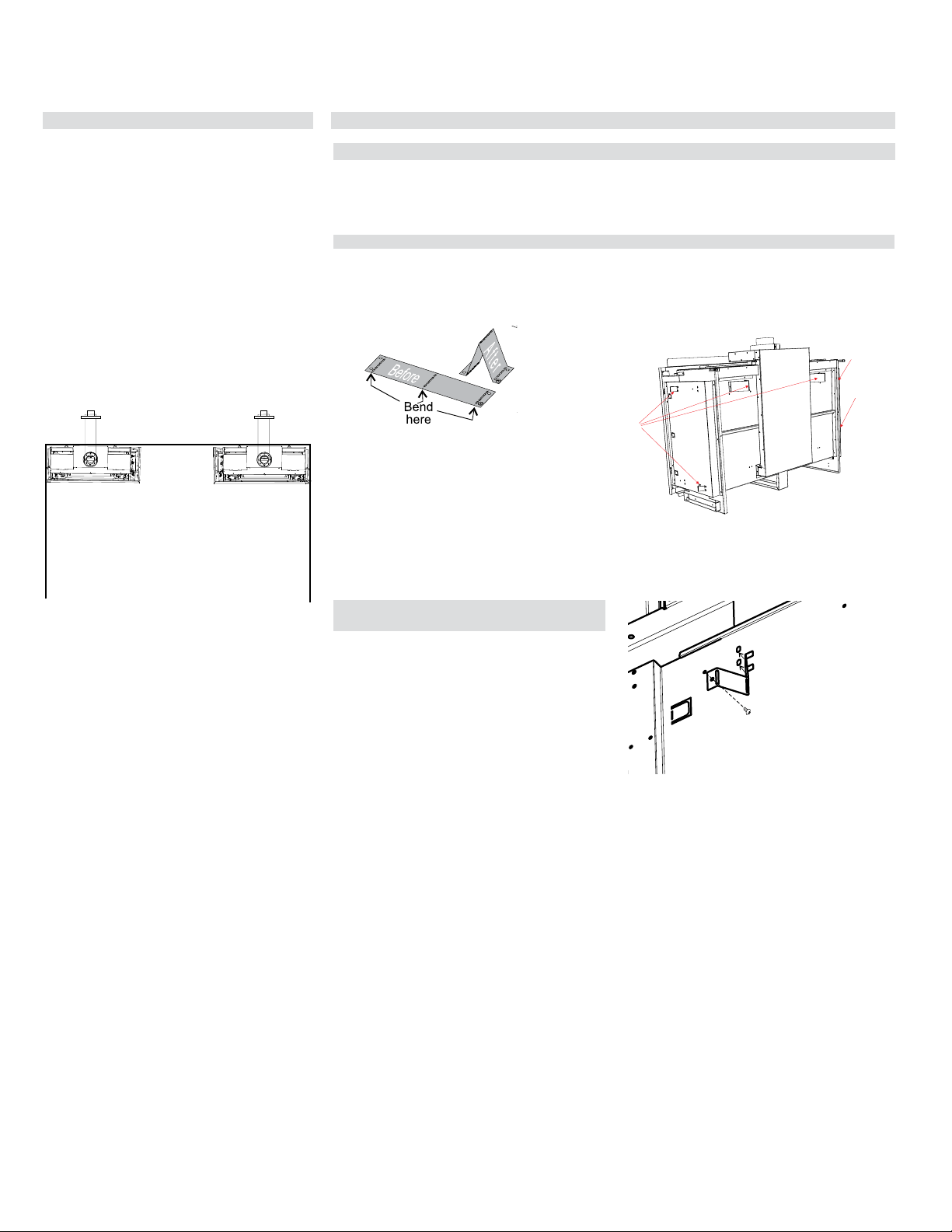
City Series CC40E-11 | 25
requirements
installer's information
Locating Your Gas Fireplace
1. When selecting a location for your fireplace,
ensure that the clearances are met.
2. The appliance must be installed on a flat, solid,
continuous surface For example a wood, metal
or concrete floor or in a raised (on the wall) ap-
plication. The appliance must be installed on
a metal or wood panel extending the full width
and depth of the appliance.
3. The CC40LE/CC40RE Direct Vent Gas Fire-
place can be installed in a recessed position
or framed out into the room as in A and B. See
Diagram 1.
A) Corner Left
A
B
Diagram 1
CC40LE/CC40RE
CC40LE/CC40RE
B) Corner Right
4. For bedroom installations, check with local
codes before installation. This appliance is
offered with a remote control.
5. The CC40LE/CC40RE Direct Vent Gas Fire-
place is approved for alcove installations, see
"Clearances" section for details.
6. We recommend that you plan your installa-
tion on paper using exact measurements for
clearances and floor protection before actually
installing this appliance. Have an authorized
inspector, dealer, or installer review your plans
before installation.
Note: For vent terminations refer to "Exterior
Vent Termination Locations" section.
Unit Assembly Prior to Installation
Before you start
The CC40LE/CC40RE has 4 standoffs, 2 on one side and 2 at the back that need assembly before
installation.
tooltip
Side and Back Standoff Assembly CC40LE/CC40RE
The standoffs are shipped in a flat position and must be folded into shape and attached.
Take each standoff off the unit by removing one screw and bend into the correct shape. Slot the 2 tabs
of the stand off into the slots in the unit and attach the other end with one screw.
Standoff
locations
Back Standoff Assembly CC40LE/
CC40RE
Take each standoff off the unit by removing one
screw. Bend into the correct shape (see above). Slot
the 2 tabs of the stand off into the slots in the unit
and attach the other end with one screw.
26 | City Series CC40E-11
installer's information
Installation Checklist
1. Locate appliance. Refer to the following sections:
a) Locating Your Fireplace
b) Clearances
c) Combustible Mantel Clearances
d) Framing & Finishing
e) Venting. See the "Venting Introduction" to
"Venting Arrangements" sections.
2. Assemble Standoffs. Refer to the "Unit Assem-
bly Prior to Installation" section. (NOTE: must
be done before installing unit into fireplace.)
3. Install vent. See the "Horizontal Installations"
to "Installation Procedures" sections.
4. Wire 120 volt AC power to the supplied
receptacle box located on lower left hand
side of appliance. The Duplex receptacle and
receptacle cover are also included and will be
located in the manual package. Note: This heater
does not require 120 volt AC supply for operation
of the burner but is highly recommended as a
primary power source to eliminate the need for
4 AA batteries. Batteries should only be used
as a secondary power source when power is
lost within the home. 120 Volt AC power is also
required for operation of the lights.
Note: The wire harness (marked receiver) is
located near the gas valve and will need to be
routed to the exterior of the fireplace from either
the left or right hand side of the appliance prior
finishing.
5. Install junction box supplied with appliance.
Install remote battery box inside of junction box.
Hook battery box to wire marked receiver. This
will enable operation of the burner. If 120 Volt
AC power was brought to appliance, batteries
are not required.
6. Make gas connections. Test the pilot. Must be as
per diagram. Refer to the "Gas Line Installation"
& "Pilot Adjustment" sections.
7. Install standard and optional features. Refer
to the following sections where applicable:
a. Safety Glass
b. Firebox (inner) glass
c. Log Set
d. Fireglass
e. Ceramic stones or other approved media
f. Painted, enamel or glass panels (panels
required)
g. Optional Framing Kit
h. HeatWave Kit
8. Plug 3 prong plug for the lights into the
receptacle. The 3 prong plug will be located
near the gas valve on the appliance.
9. Final check.
Before leaving this unit with the customer, the
installer must ensure that the appliance is firing
correctly and operation fully explained to customer.
HeatWave Duct System Optional
Kit
The HeatWave Air Duct Kit increases the
effectiveness of your fireplace by dispersing warm
air from the fireplace to remote locations in the same
room or other rooms in your home.
Up to two kits may be installed on the fireplace.
Please Note: One adaptor kit #656-995 must be
used with each 946-556.
The HeatWave Duct Kit has different clearance
and framing requirements, check the HeatWave
manual for details.
This includes:
1. Clocking the appliance to ensure the correct
firing rate (rate noted on label 28,500 Btu/h NG/
LP) after burning appliance for 15 minutes.
2. If required, adjusting the primary air to ensure
that the flame does not carbon. First allow the
unit to burn for 15-20 min. to stabilize.
CAUTION: Any alteration to the product that causes
sooting or carboning that results in damage
is not the responsibility of the manufacturer.
Note: If using the optional Heatwave kit, this
does not reduce the size of the ventilation
opening The ventilation opening must be a
minimum 120 square inches regardless.
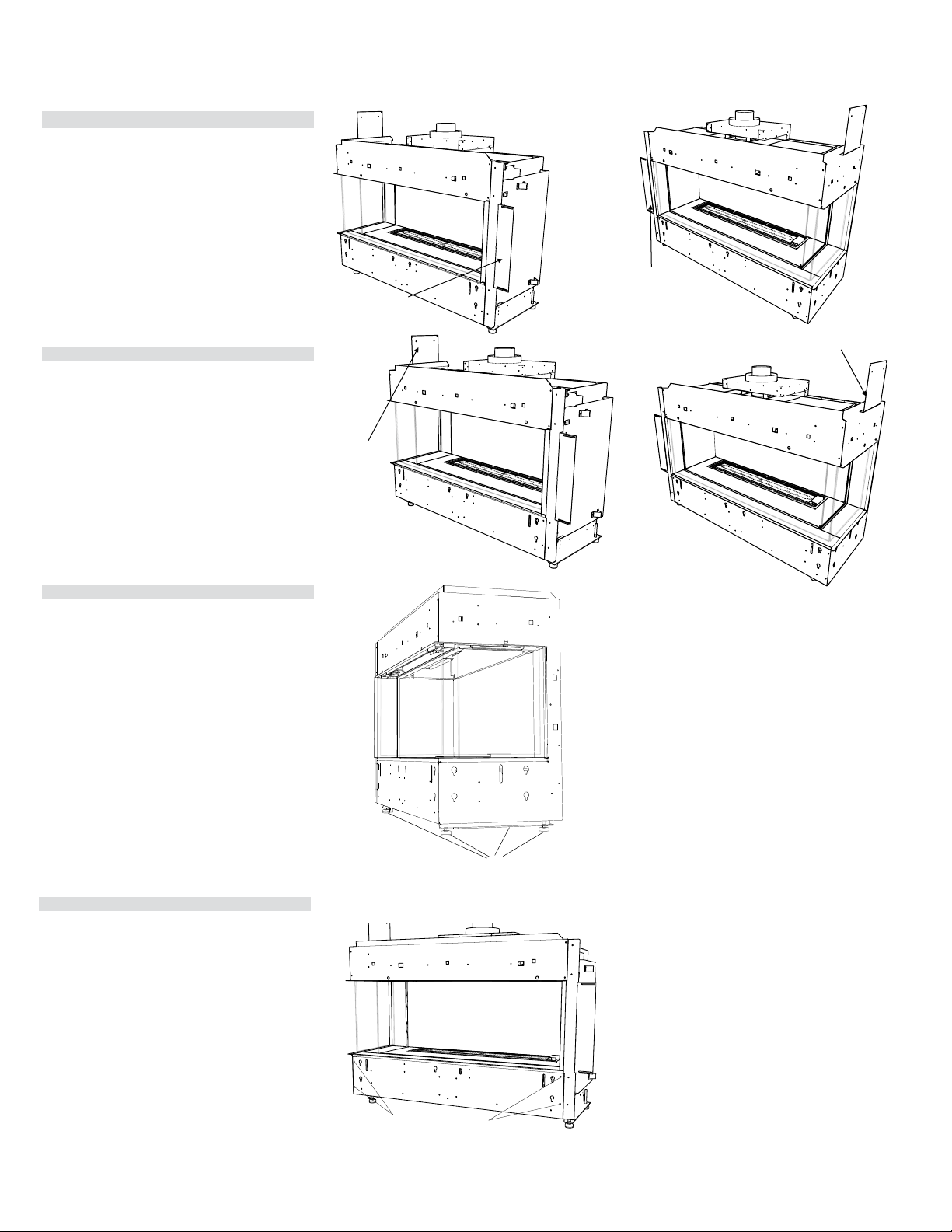
City Series CC40E-11 | 27
installation
Nailing Strips
Nailing strips are shipped folded flat against the unit.
Fold nailing strips out 90º before installing unit.
Secure nailing strips to framing using wood or
metal screws.
Levelling Bolts
There are four levelling bolts - two on each side
that can be adjusted if required.
Access Panel Removal
The front access panel may be removed for ease
of hooking up gas and electrical. Once complete
ensure that the access panel is reinstalled prior to
any finishing.
The CC40LE/CC40RE has 4 screws to remove
access cover. See locations in diagram to the right.
Side nailing strip
CC40LE
tooltip
Side nailing strip
CC40RE
Top Nailing Strip
Nailing strip is shipped with the appliance and will
need to be attached. Note that the nailing strips are
not required if using the optional chase or extended
framing kit and may be recycled.
1. Secure nailing strip to appliance with 2 screws.
2. Secure nailing strips to framing using wood or
metal screws.
Leveling bolts
Top nailing strip
tooltip
Top nailing strip
Access panel screws
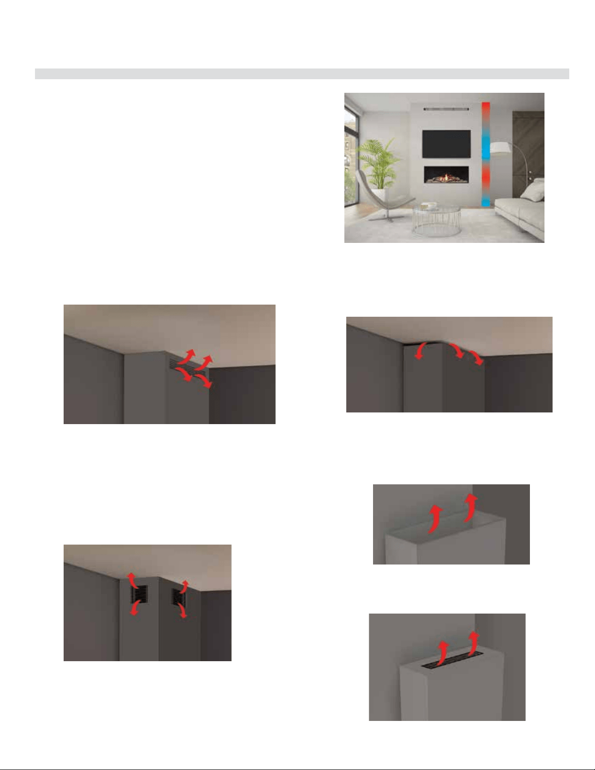
28 | City Series CC40E-11
installer's information
Ventilation Openings
Regency's patented Cool Wall system releases warmth at ceiling level. This
system reduces excessive radiant heat in front of the fireplace so you can
enjoy your fireplace more often.
• Design your own chase vent solution to suit your home
• Use optional front or left & right side chase vent grills
• Release warmth into the room discreetly
Front Exit
The ventilation opening may be placed in front ensuring it meets the 120
square inch opening & is located 0-3" (76mm) from the enclosure ceiling.
Side/Front Exit
Ventilation openings, when placed on the side, must also have the same size
ventilation opening in front. They must be have an equal split (50/50) free air
opening to balance air flow. A ventilation opening may never be on one side
only.
The side ventilation opening cannot be any smaller than 6" (152mm) wide to
equal the total area of 120 square inches of free open area.
Example: 6" (152mm) wide x 10" (254 mm) High = 60 square inches of free
open area. A second ventilation grill is installed in front to =100%.
The ventilation openings must be located 0-3" from the enclosure ceiling.
Top Exit
The ventilation opening may be short of the ceiling as shown below.
Minimum width/depth of chase x height is measured from top of enclosure
to the ceiling and must be in open in front and side to meet the minimum
120 square inches free open air requirement.
Ventilation Opening Locations
The following are examples of how the ventilation openings may be placed
above the fireplace.
If using the optional heat wave kit, this does not reduce the size of the
ventilation opening. The ventilation opening(s) must be a minimum 120
square inches regardless.
The air travelling through the heat exchanger is heated by the fireplace and
then directed out the back of the fireplace. The combined warmed air is then
vented back into the room.
The ventilation opening may be fully open at the top of the enclosure. This
type of ventilation opening would be used when the top of the enclosure
is not visible from above and where the ceiling within the room is higher
than normal. When creating this type of ventilation opening, measures
should be into place to avoid having objects of any type falling or be
thrown into the ventilation opening. Mesh screen or other preventative
measures should be put into place.
The ventilation opening may be placed on top ensuring it meets the 120
square inch opening. This type of ventilation opening would be used
when the top of the enclosure is visible from above and where the ceiling
within the room is higher than normal.
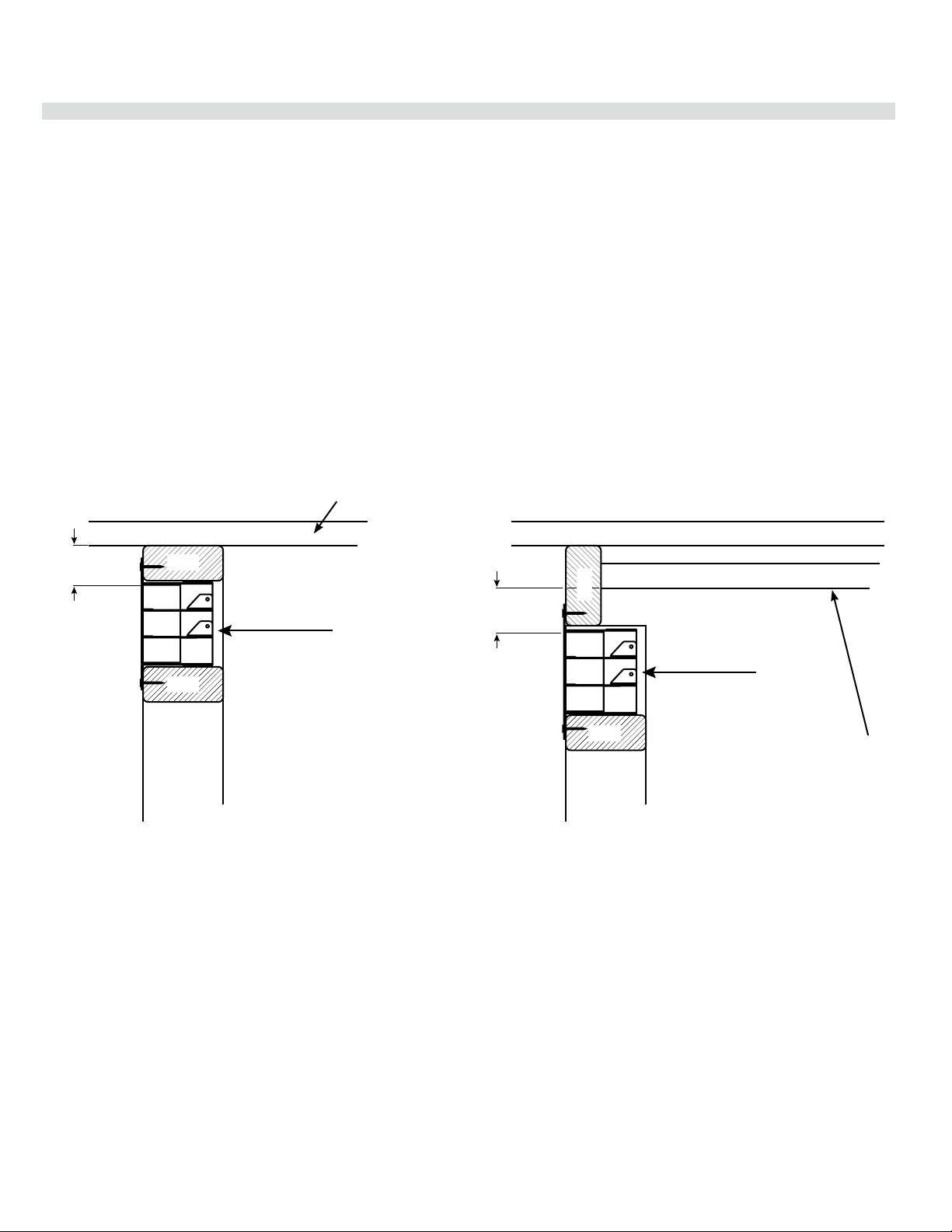
City Series CC40E-11 | 29
requirements
installer's information
Chase Enclosure
Max 3”
(76 mm)
Ceiling
Ceiling
Top of chase enclosure
Max 3”
(76 mm)
Stud
Stud
Stud
Stud
40” (1016 mm) Chase Vent
C40 Chase Vent Framing Clearances
Opening for vent
4”-4.5”
(102 mm x 114 mm)
Min 42.25” (1073 mm)
Framed opening must be between 4” (102 mm) and 4.5” (114 mm) tall, and at least 42.25”(1073 mm) wide
to accommodate the chase vent. The top of the chase vent opening must be 3” or less from the top of the
chase enclosure.
40” (1016 mm) Chase Vent
Top of chase enclosure
In the example above, the ceiling does not
meet the requirement as it is higher than
the specified minimum.
Top of chase enclosure is sealed off to
meet the 0-3 (76 mm) requirement.
Top of chase enclosure
Minimum 120sq. inch opening
Minimum 120sq. inch opening
When choosing to install the ventilation openings from the front or both sides, The top of the ventilation opening cannot be any lower than 0-3" from the top
of the chase enclosure for all installations.
Minimum height of enclosure from base of appliance is 63".
A minimum 120in
2
opening in the enclosure is required to maintain safe operating temperatures. This can be achieved in a number of ways including the
examples shown in this manual.
IMPORTANT:
Exterior wall/Alcove enclosure: When installing into an exterior cavity or alcove enclosure (ceiling, back and sides), regardless of where appliance is placed
within the home, requires the use of either drywall or other means such as plywood, wood studs, etc. to prevent heat from escaping anywhere above/through
the enclosure other than the required grill/ventilation openings.
Internal chase: When installing as an internal chase framing installation, regardless of where appliance is placed within the home, requires the use of either
drywall or other means such as plywood, on the rear wall of the chase to eliminate heat escaping into the rear wall cavity. If the chase is extended to the ceil-
ing, the ceiling will also need to be finished in a manner to prevent heat escaping into floor joist/attic space.
One of the following methods must be used to prevent the heat from escaping:
a. If choosing drywall, ensure that the drywall is butt up tight with no gaps.
b. Plywood, wood studs, etc. installed tightly with no gaps.
As this appliance has been designed with all hot air escaping through the chase enclosure ventilation/grill openings only, if hot air is trapped as a result of
the hot air escaping through joints, crevasses, open studs, or other openings within the enclosure above, this will change the clearances within the enclosure
causing the enclosure to overheat. It is vital that all the hot air from within the enclosure exits through the ventilation openings only.
Ensure that the ventilation openings are made as such to prevent debris, objects from falling into the enclosure.
Warning: DO NOT cover or place objects in front of the ventilation opening air outlet(s).
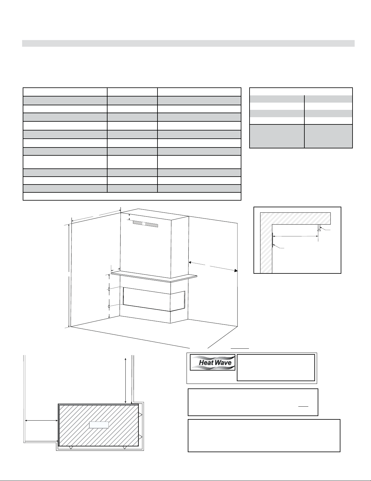
30 | City Series CC40E-11
installation
Caution Requirements
The top, back and sides of the fireplace are defined by
standoffs. The metal ends of the standoff may NOT be
recessed into combustible construction.
WARNING
Fire hazard is an extreme risk
if these clearances (air space) to combustible materials are not
adhered to. It is of greatest importance that this fireplace and vent
system be installed only in accordance with these instructions.
Clearances
The clearances listed below are minimum distances unless otherwise stated:
A major cause of chimney related fires is failure to maintain required clearances (air space) to combustible materials. It is of the greatest importance that this
fireplace and vent system be installed only in accordance with these instructions.
Note: CC40LE shown in illustration. Clearances will be the same for the CC40RE.
Clearance: single sided Dimension Measured From:
A: Mantel Height (min.) ** Top of Fireplace Opening
B: Opening Height 15-1/16" (382mm) Bottom/Top of Fireplace Opening
C: From Floor Min. 0" Bottom of Fireplace Opening
D: Sidewall (on one side) Min. 36" (914mm) Side of Fireplace Opening
E: Mantel Depth (Max.) ** Front of Fireplace Opening
F: Alcove Depth Min. 36" (914mm) Front of Fireplace Opening
G: Convection Air Outlet * Top of Enclosure
H: Convection Air Outlet Opening
Offset
0-3" (76mm)
Max. offset from top of chase
enclosure
I: Chase Enclosure (Min.) 63" (1600mm) From Base of Unit
J: Clearance to sprinkler head (Min.) 36" (914mm) Perpendicular from chase grill
Hearth 0" No hearth required
** See mantel clearances chart in this manual.
Flue Clearances to Combustibles
Horizontal - Top 3"
Horizontal - Side 2"
Horizontal - Bottom 2"
Vertical 2"
Passing through wall/
floor/ceiling - when
firestop is used.
1-1/2"
Top View
Alcove
The HeatWave Duct Kit has differ-
ent clearance and framing require-
ments, check the HeatWave manual
for details.
*A minimum of 120 square
inches of open area, not
lower than 3" from top of
enclosure, required for all
installations
H
I
A
E
B
C
G
D
F
D
F
CC40 UNIT
Side view
L
Chase grill
Sprinkler
J
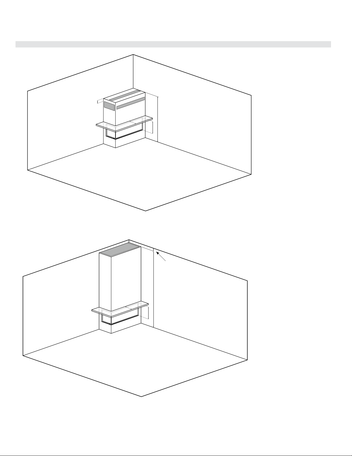
City Series CC40E-11 | 31
installation
Clearances
CC40LE shown
CC40LE shown
E
G
G
G
H
B
I
L
o
w fr
a
min
g
wi
t
h v
e
n
ts
E
G
B
H
I
Fl
oo
r
to
ce
ilin
g
wi
t
h
top
op
Width of chase x
height from top of
chase to ceiling
must be no less
than 120 square
inches.
Floor to ceiling with top opening
Low framing with vents in front/sides or top
Note: Ventilation opening may never be on one side only.
Note: The ventilation opening may only be placed above, on side/front
and in front as shown above and on the next page.
Ventilation grills can never be placed behind the appliance.
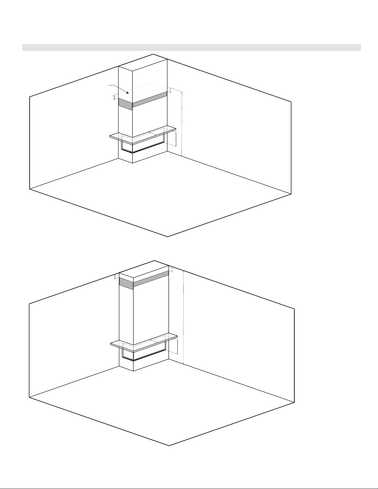
32 | City Series CC40E-11
installation
Clearances
CC40LE shown
CC40LE shown
Chase enclosed
H
E
B
I
H
G
G
H
E
B
I
H
G
G
Full framing with vents in front or sides
Note: Ventilation opening may never be on one side only.
Full framing with low vents in front or side/front
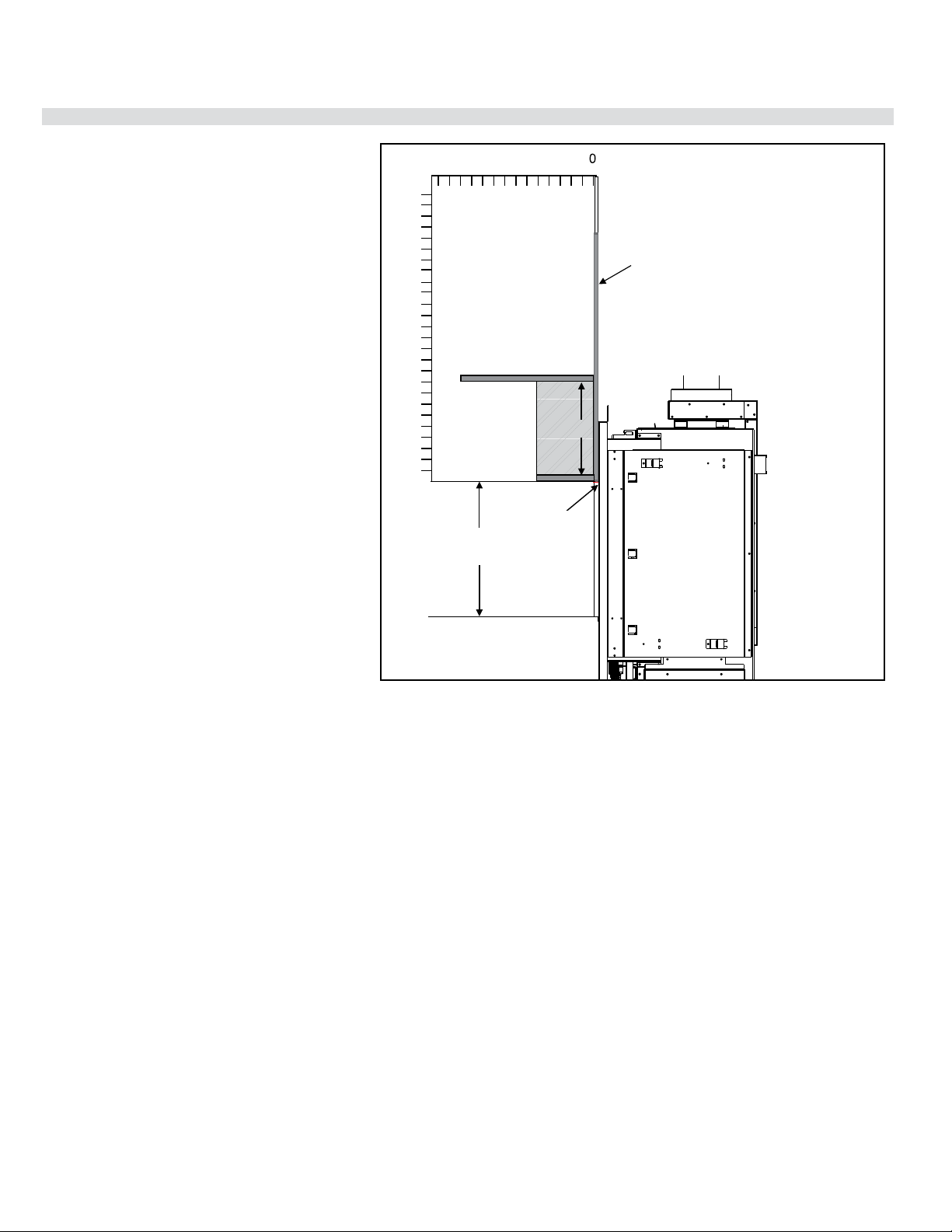
City Series CC40E-11 | 33
installation
Mantel Clearances
Combustible mantel clearances from top of front facing
are shown in the diagram on the right.
212 6 4810
0
14
9
" (229 m)
15-1/16”
(383 mm)
10
20
26
Top of
Fireplace
Opening
12" (305 mm)
1/2" (13 mm) Drywall, wood,
wood panel, etc.
5-1/8"
(130 mm)
To
Bottom
of
Fireplace
Opening

34 | City Series CC40E-11
installation
Framing Dimensions (Left Corner)
NOTE: Framing may be constructed of combustible material (ie. 2 x 4)and does not require steel studs.
Note: A combined minimum of
120 square inches of open area
is required for the convection air
outlet to cool the enclosure. En-
sure clearances for Convection Air
Outlets are met.
See clearances CC40LE/CC40RE
(single sided) in this manual as there
are different methods as to how this
can be achieved.
Framing
Dimensions
Description CC40LE
A Framing Height 37-3/8” (949mm)
B* Framing Width 48-1/4" (1226mm)
C* Framing Depth 19" (483mm)
D Unit Base to Top Enclosure (Min.) 63"(1600mm)
G Vent Centerline Height 56-1/4" (1429mm)
NOTE: Unit cannot be load-bearing. All finishing materials must be supported by the framing.
Note: This appliance must be in-
stalled on a level and solid surface
such as a plywood floor which must
be the full width and depth of the
appliance.
* The framing depth/width does not take into account dry wall/wood
or similar materials against the back /side wall. The framing depth
will need to change based on the thickness of the material
(example: B - 48 1/4" framing width +1/2" drywall = 48 3/4")
(example: C - 19" framing depth +1/2" drywall = 19 1/2")
*
*
Maximum material dimen-
sions 2" x 4" for wood
studs in front and side
studs behind can be either
2'' x 4'' or 2'' x 6''.
Note: Wood
header on
edge may be
2'' x 4'' or
2'' x 6''.
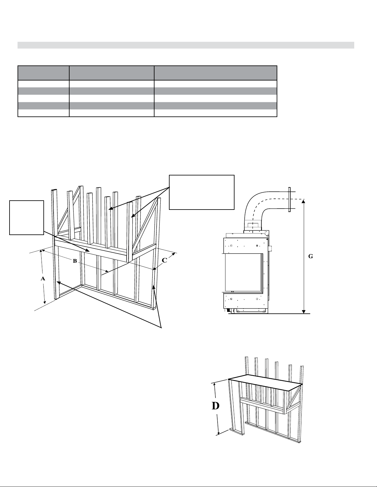
City Series CC40E-11 | 35
installation
Framing Dimensions (Right Corner)
NOTE: Framing may be constructed of combustible material (ie. 2 x 4)and does not require steel studs.
Framing
Dimensions
Description CC40RE
A Framing Height 37-3/8” (949mm)
B* Framing Width 48-1/4" (1226mm)
C* Framing Depth 19" (483mm)
D Unit Base to Top Enclosure (Min.) 63"(1600mm)
G Vent Centerline Height 56-1/4" (1429mm)
Note: A combined minimum of
120 square inches of open area
is required for the convection air
outlet to cool the enclosure. En-
sure clearances for Convection Air
Outlets are met.
See clearances CC40RE (in this
manual) as there are different meth-
ods as to how this can be achieved.
Note: This appliance must be in-
stalled on a level and solid surface
such as a plywood floor which must
be the full width and depth of the
appliance.
NOTE: Unit cannot be load-bearing. All finishing materials must be supported by the framing.
*The framing depth/width does not take into account dry wall/wood
or similar materials against the back /side wall. The framing depth
will need to change based on the thickness of the material
(example: B - 48 1/4" framing width +1/2" drywall = 48 3/4")
(example: C - 19" framing depth +1/2" drywall = 19 1/2")
*
*
Maximum material dimen-
sions 2" x 4" for wood
studs in front and side
studs behind can be either
2'' x 4'' or 2'' x 6''.
Note: Wood
header on
edge may be
2'' x 4'' or
2'' x 6''.
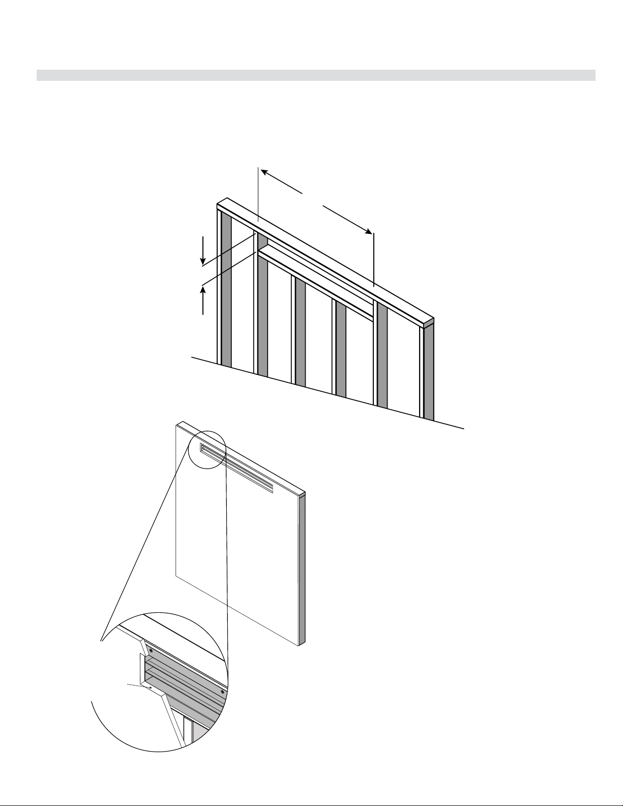
36 | City Series CC40E-11
installation
Optional Flush Front Chase Vent Installation - Part #657-991 (White)
Max 3”
(76 mm)
Ceiling
Ceiling
Top of chase enclosure
Max 3”
(76 mm)
Stud
Stud
Stud
Stud
40” (1016 mm) Chase Vent
C40 Chase Vent Framing Clearances
Opening for vent
4”-4.5”
(102 mm x 114 mm)
Min 42.25” (1073 mm)
Framed opening must be between 4” (102 mm) and 4.5” (114 mm) tall, and at least 42.25”(1073 mm) wide
to accommodate the chase vent. The top of the chase vent opening must be 3” or less from the top of the
chase enclosure.
40” (1016 mm) Chase Vent
Drywall
Header Stud
C40 Chase Vent Finish Detail
Finish edges of drywall
with trim or corner bead.
Edge finish must not decrease
opening area below 130in (3.25" x
40") or (83 mm x 1016 mm)
Finish edges of drywall
with trim or corner bead.
Edge nish must not de-
crease opening area be-
low 130in (3.25'' x 40'') or
(83mm x 106mm)
This optional flush front chase vent grill is designed so that only the grills are exposed. The 4 flanges in front which secure the chase vent grill to the stud work
are covered by the drywall to give a seamless look.
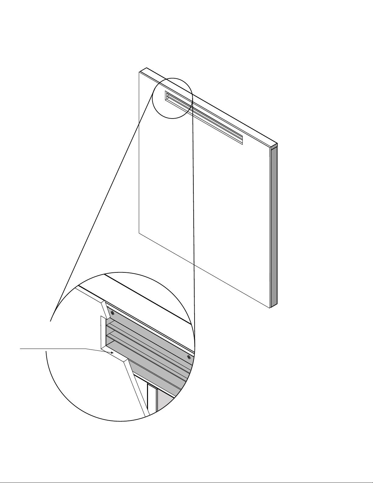
City Series CC40E-11 | 37
installation
Drywall
Header Stud
C40 Chase Vent Finish Detail
Finish edges of drywall
with trim or corner bead.
Edge finish must not decrease
opening area below 130in (3.25" x
40") or (83 mm x 1016 mm)
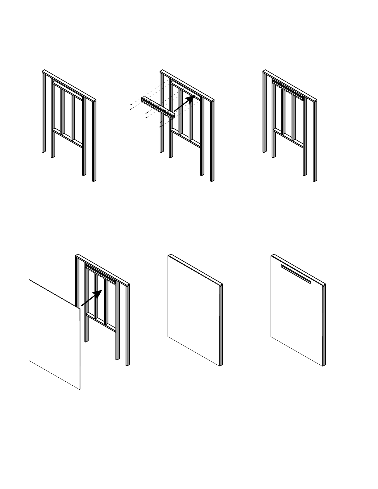
38 | City Series CC40E-11
installation
C40 Chase Vent Installation Example
1. 2. 3.
4. 5. 6.
Frame opening for vent
(See Vent Framing Clearances Page)
Screw Chase vent to Framing Use at least 3 sets of screws
to keep the vent at against framing
Frame wall with nishing material If necessary, mark where the
chase vent is located before
fixing drywall in place
Cut hole in nishing material
around inside of chase vent.
Finish edges around opening
Drywall
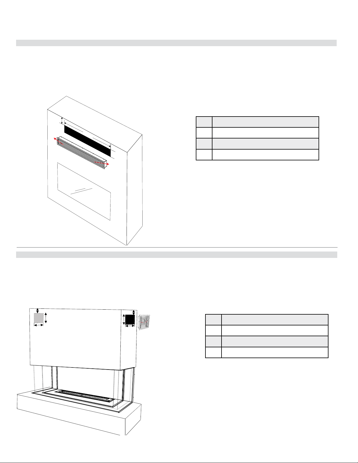
City Series CC40E-11 | 39
installation
Optional Front Grill Installation - Part #656-991 (Black)
A
B
C
B
A
C
Optional Side Grill Installation - Part # 656-992 (Set of 2/Black)
Unit may not be exactly as shown,
but the drawing dipicts the process.
A
C
B
DIMENSIONS
A 39-1/8'' (994mm)
B 4-3/8'' (111mm)
C Maximum 3'' (76mm) from top of enclosure.
Secure with screws from the front through the sides.
DIMENSIONS
A Maximum 3'' (76mm) from top of enclosure.
B 8-5/16'' (211mm)
C 8-5/16'' (211mm)
Secure with screws through louvers to the sides.
This optional grill meets the requirement of the 120 square inches required for the enclosure in all installations and is designed to keep the enclosure cool.
In this application, both the flange and screws to secure the grills are exposed as this grill is designed to be installed after the finished facing has been placed
on the wall.
To install the front grill - frame an opening of 4-3/8'' H x 39-1/8'' W (111mmm H x 994mm W).
The finished facing material should be attached and be the same size as the framed opening to eliminate gaps.
Install the grill and secure in place with one screw on either side, installed from the front.
These optional grills meet the requirement of the 120 square inches required for the enclosure in all installations and are designed to keep the enclosure cool.
In this application, both the flange and screws to secure the grills are exposed as this grill is designed to be installed after the finished facing has been placed
on the wall.
To install the side grills - frame an opening of 8-5/16'' H x 8-5/16'' W (211mm H x 211mm W).
The finished facing material should be attached and be the same size as the framed opening to eliminate gaps.
Install the grill and secure in place with one screw on either side, installed from the front through the louvers.
Repeat steps to install the second grill to the other side of the chase.
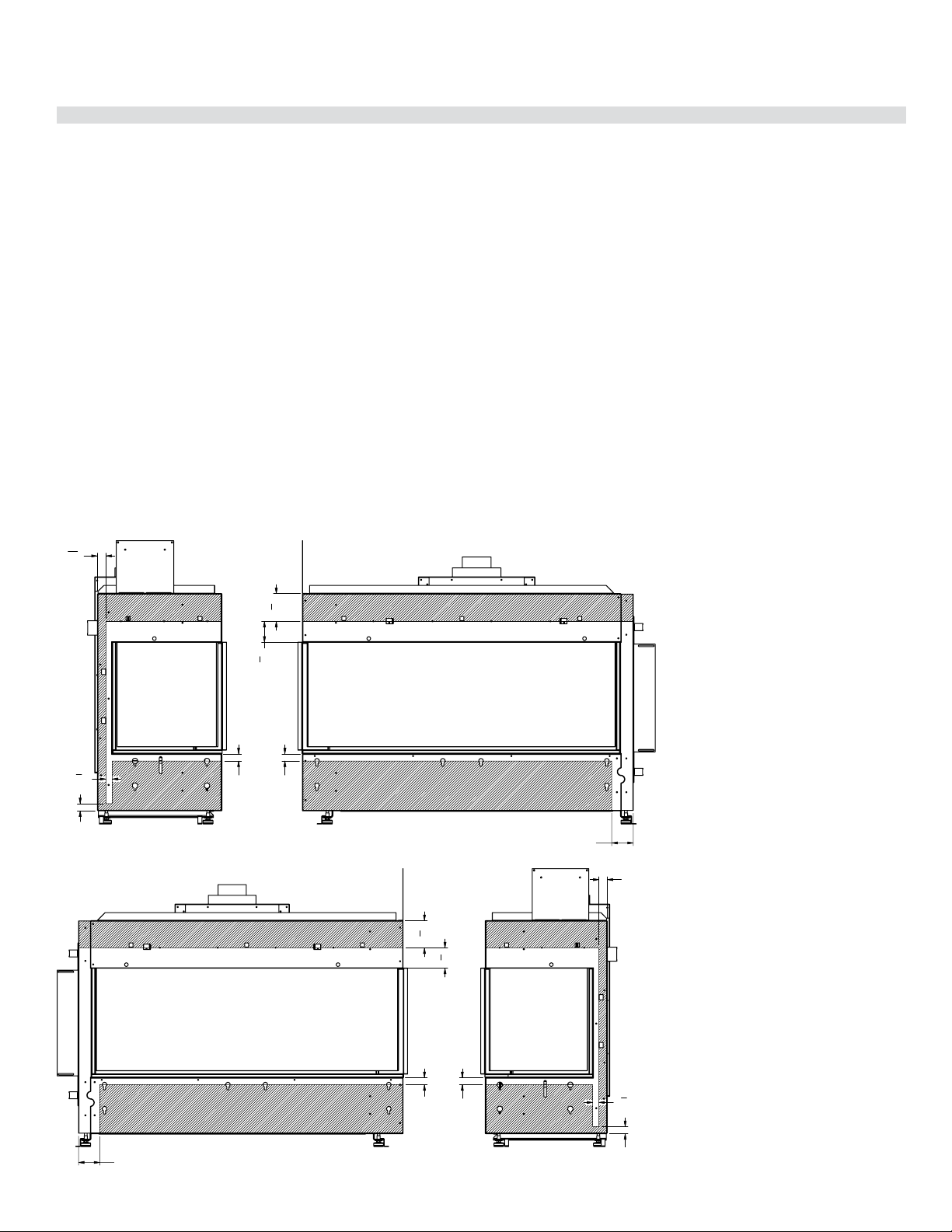
40 | City Series CC40E-11
installation
Wall Board/Drywall Installation
WARNING! Risk of Fire! Comply with all minimum clearances to combustibles as specified.
Finishing Instructions
It is important to follow the framing and finishing instructions to ensure proper placement of fireplace into the surrounding framing/finishing materials.
Wall board materials 1/2 in. thick are specified in this installation manual to properly align with the optional finishing methods offered with this appliance. The
CC40LE/CC40RE may be finished to the appliance opening with 1/2 inch thick drywall.
• Ensure that the back and side clearances are maintained.
WARNING! Risk of Fire! Maintain specified air space clearances to combustibles. Inadequate air space could cause overheating and fire.
DO NOT use screws more than 3/4 inch in length on the lower access cover panel. Longer screws may penetrate gas line or damage valve or electrical
components.
Note: It is acceptable to use a high temperature silicone sealant to adhere drywall to lower access cover panel.
The appliance is designed to be used with 1/2 in. wall sheathing materials such as drywall, plywood, wood composites, or non-combustible materials.
Thicker materials may be used. Refer to facing and finishing details in this manual.
Facing Material
• Facing and/or finishing materials must never overhang into the glass opening.
• Facing materials may be combustible or non-combustible
WARNING! Risk of Fire! DO NOT apply combustible materials beyond the minimum clearances. Comply with all minimum clearances to combustibles as
specified in this manual. Overlapping materials could ignite and will interfere with proper operation.
PAINTING
If desired finishing includes a painted wall, 100% acrylic latex, oil-based or standard acrylic paints may be used.
Follow paint manufacturer’s instructions for paint and primer application.
3
7
8
"
[99mm]
2
7
8
"
[73mm]
1"
[25mm]
3"
[76mm]
1"
[25mm]
1"
[25mm]
1
3
16
"
[30mm]
7
8
"
[22mm]
3
7
8
"
[99mm]
2
7
8
"
[73mm]
1"
[25mm]
3"
[76mm]
1.188
[30mm]
1"
[25mm]
7
8
"
[22mm]
1"
[25mm]
CC40LE - screws in shaded area only
CC40RE - screws in shaded area only
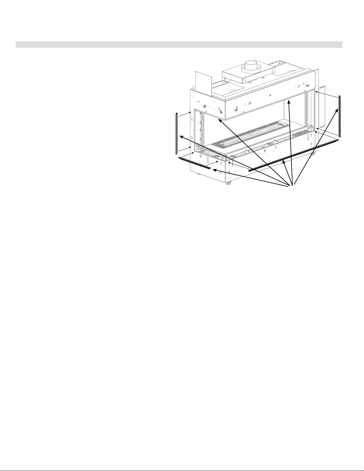
City Series CC40E-11 | 41
installation
1. Frame in the enclosure for the unit with framing material
Note: When constructing the framed opening ensure there is sufficient
access to install the gas lines,electrical. Also the wiring harness must be
wall mounted using the receptacle provided with the appliance. The wiring
harness will be located on the right hand side of the appliance if facing the
unit from the front. This must be done prior to any finishing.
2. For exterior walls, insulate the enclosure to the same degree as the rest
of the house, apply vapour barrier and drywall, as per local installation
codes. (Do not insulate the fireplace itself.)
WARNING: Failure to insulate and add vapor barriers to the inside of the
exterior wall will result in operational and performance problems including, but
not limited to: excessive condensation on glass doors, poor flame package,
carbon, blue flames etc. These are not product related issues.
3. IMPORTANT:
Exterior wall/Alcove enclosure: When installing into an exterior cav-
ity or alcove enclosure (ceiling, back and sides), regardless of where
appliance is placed within the home, requires the use of either drywall
or other means such as plywood, wood studs, etc. to prevent heat from
escaping anywhere above/through the enclosure other than the required
grill/ventilation openings.
Internal chase: When installing as an internal chase framing installa-
tion, regardless of where appliance is placed within the home, requires
the use of either drywall or other means such as plywood, on the rear
wall of the chase to eliminate heat escaping into the rear wall cavity. If
the chase is extended to the ceiling ,the ceiling will also need to be fin-
ished in a manner to prevent heat escaping into floor joist/attic space.
One of the following methods must be used to prevent the heat from
escaping:
a. If choosing drywall, ensure that the drywall is butt up tight with no
gaps.
b. Plywood, wood studs, etc. installed tightly with no gaps.
As this appliance has been designed with all hot air escaping through
the chase enclosure ventilation / grill openings only, if hot air is trapped
as a result of the hot air escaping through joints, crevasses, open studs,
or other openings within the enclosure above, this will change the clear-
ances within the enclosure causing the enclosure to overheat. It is vital
that all the hot air from within the enclosure exits through the ventilation
openings only.
Ensure that the ventilation openings are made as such to prevent debris,
objects from falling into the enclosure.
Warning: DO NOT cover or place objects in front of the ventilation open-
ing air outlet(s).
Note that in all applications while there is a zero clearance to combustibles
to the unit, all clearances to combustibles from the venting inside the chase
still applies. Please see venting clearances in the specific product manual.
4. Combustible material (drywall, wood, wood panels, etc.) may be brought
up to this appliance (top,bottom and sides)
5. Ensure that the material being used does not encroach anywhere in the
area of the glass. This would cause dangerous operating conditions.
6. This appliance comes with a 1/2" lip at top, sides and bottom to hide the
ends of the drywall. The 1/2" side and bottom, front and bottom side lips
supplied with the appliance can alternatively be removed and replaced
with J Style Trim or Metal Corner Bead purchased at your local hardware
store to cover cut/exposed edges of the combustible facing material or
any other finishing materials being used. Six (6) screws secure the bot-
tom front lip. Two (2) secure the bottom side lips and 2 secure the side
if deciding to remove these. These will be hidden so the outer panels (if
installed) will need to be removed to access the screws. See outer panel
removal in this manual.
7. This appliance can also be recessed (using combustible materials) with a
hearth in front of the appliance. This can also extend to the top.
8. The wall behind the unit must be closed off.
Framing and Finishing Inset Installations
**Combustible material may extend a minimum of 1/2" and to a maximum of
5-1/8" (130mm) from the Front top. See mantle clearance chart for details.
The base and side (with smaller glass) have no limit when it comes to how
far the combustible material may extend out from the appliance. Ensure
that no material encroaches anywhere in the area of the glass as these are
defined by the finishing lip above, below and to the sides of this appliance.
Note: an offset screwdriver is provided with the appliance for ease of removal/
installation.
Finishing lip
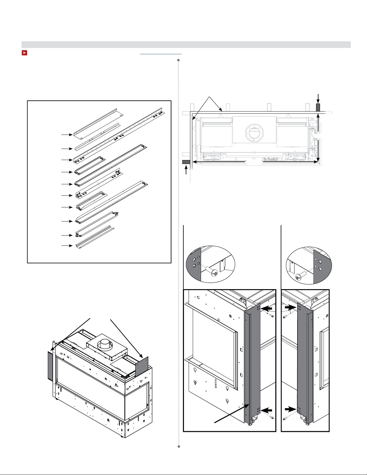
42 | City Series CC40E-11
installation
Optional Framing Kit Installation (Part # 656-953)
919-773a
01.21.19
CC40LE/CC40RE FRAMING KIT INSTALLATION
This framing kit is for the CC40LE/CC40RE. The parts are adaptable so
the same kit can be installed on either the right or left side units.
NOTE: CC40RE SHOWN IN DIAGRAMS
Installation is the same for CC40LE, please note that images will appear
fl ipped.
Unit nailing strips are not required and can be recycled when using the
framing kit.
2. Begin with the unit away from the wall. Install part A to the back of the
unit using holes next to appropriate shape (diamond or square depending
on which unit you have) using the diagrams below. Attach to the back
of the unit using 2 screws in locations shown below.
1. This framing kit requires the installation of two studs at locations shown
below. Be sure to install studs and walls to enclose chase (see Unit
Manual) prior to moving the unit into position.
Remove nailing fl anges
Shown for CC40RE
Measured from wall to stud center
CC40RE
Holes next to squares
CC40LE
Holes next to diamonds
A 656-391
B 656-392
2x C 656-393
D 656-396
E 656-394
F 656-398
G 656-397
H 656-395
J 656-399
K 656-400
18"
49 3/4"
Stud
Stud
A
NOTE: CC40LE use holes corresponding with diamond shape.
CC40RE use holes corresponding with square shape.
walls (ie. drywall)
1
CITY SERIES
To watch the framing kit installation video click here http://bit.ly/2qvHIsE
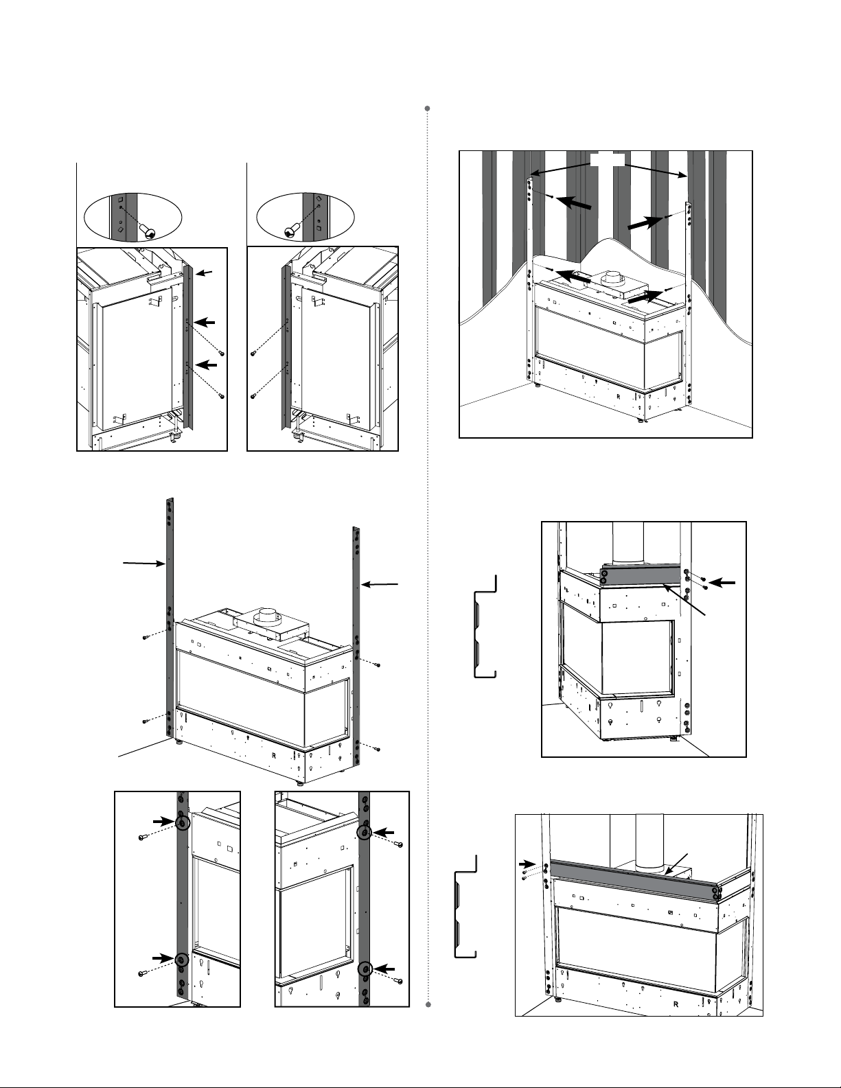
City Series CC40E-11 | 43
installation
919-773a
04.24.17
5. Slide unit against wall and line up part C's with studs in the wall.
Attach both part C's to studs with at least two screws each; one at
the top, and one near the unit (as seen below).
8. Identify E (see diagram below), attach E to front corner C with 2 screws
as shown below.
D
C
C
4. Install 2 x part C's onto parts A & B respectively, identify the holes to
be used, attach to the unit with 2 screws each.
Part D Profi le
3. Install B to the side of the unit, use the holes corresponding with the
appropriate shape (diamond or square depending on which unit you
have) using the diagrams below. Attach B to the side of the unit and
install 2 screws in locations shown below.
E
Part E Profi le
6. Install venting before proceeding further with framing kit construction.
Refer to manual for venting instructions.
7. Identify D, attach to back corner C with 2 screws as shown below.
B
CC40RE
Holes next to squares
CC40LE
Holes next to diamonds
Studs
2
CITY SERIES
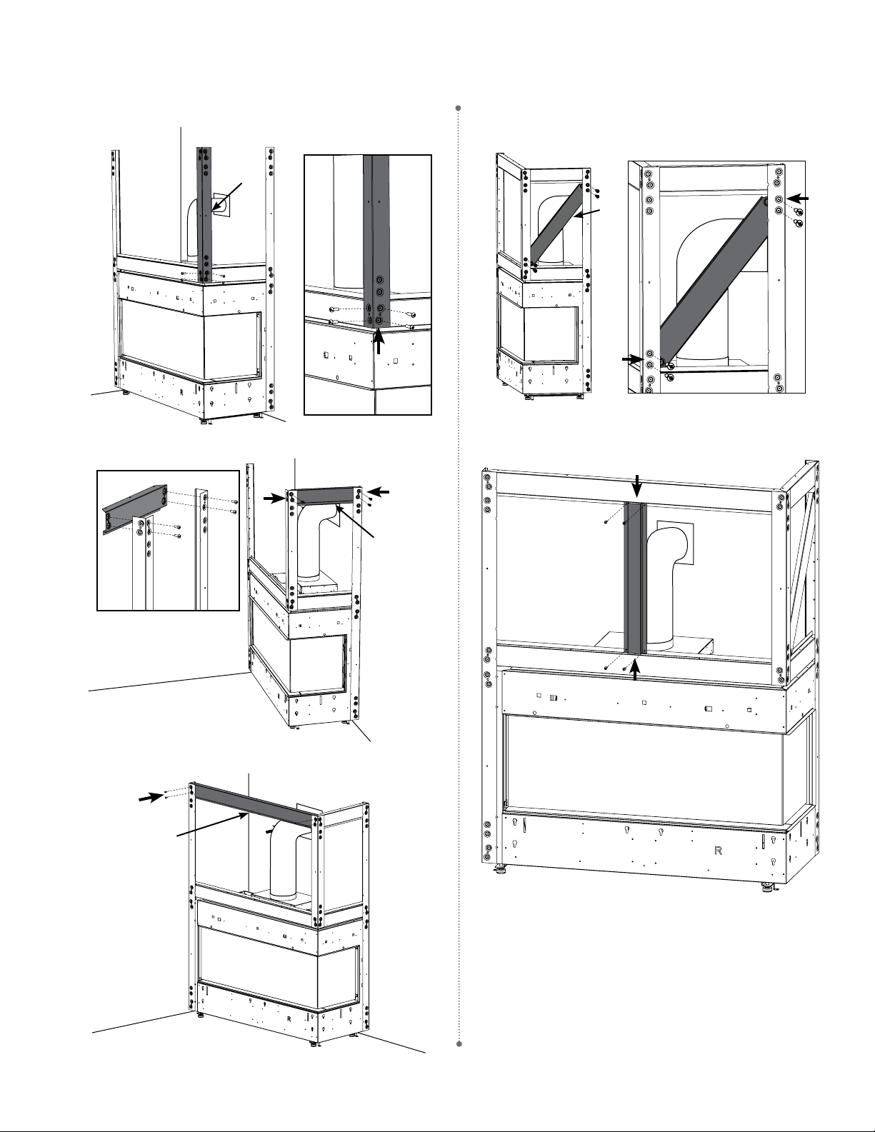
44 | City Series CC40E-11
installation
919-773a
04.24.17
9. Identify F and attach to both E and D with 2 screws on each side.
10. Identify G and attach to back corner C and front corner F with 2
screws on each side.
11. Identify H and attach to both front corners C and F with 2 screws
on each side.
12. Identify J (diagonal support) and attach to back corners C and front
corner F with 2 screws on each side.
13. Attach K (center support) to E and H with 2 screws each.
F
J
K
H
G
3
CITY SERIES
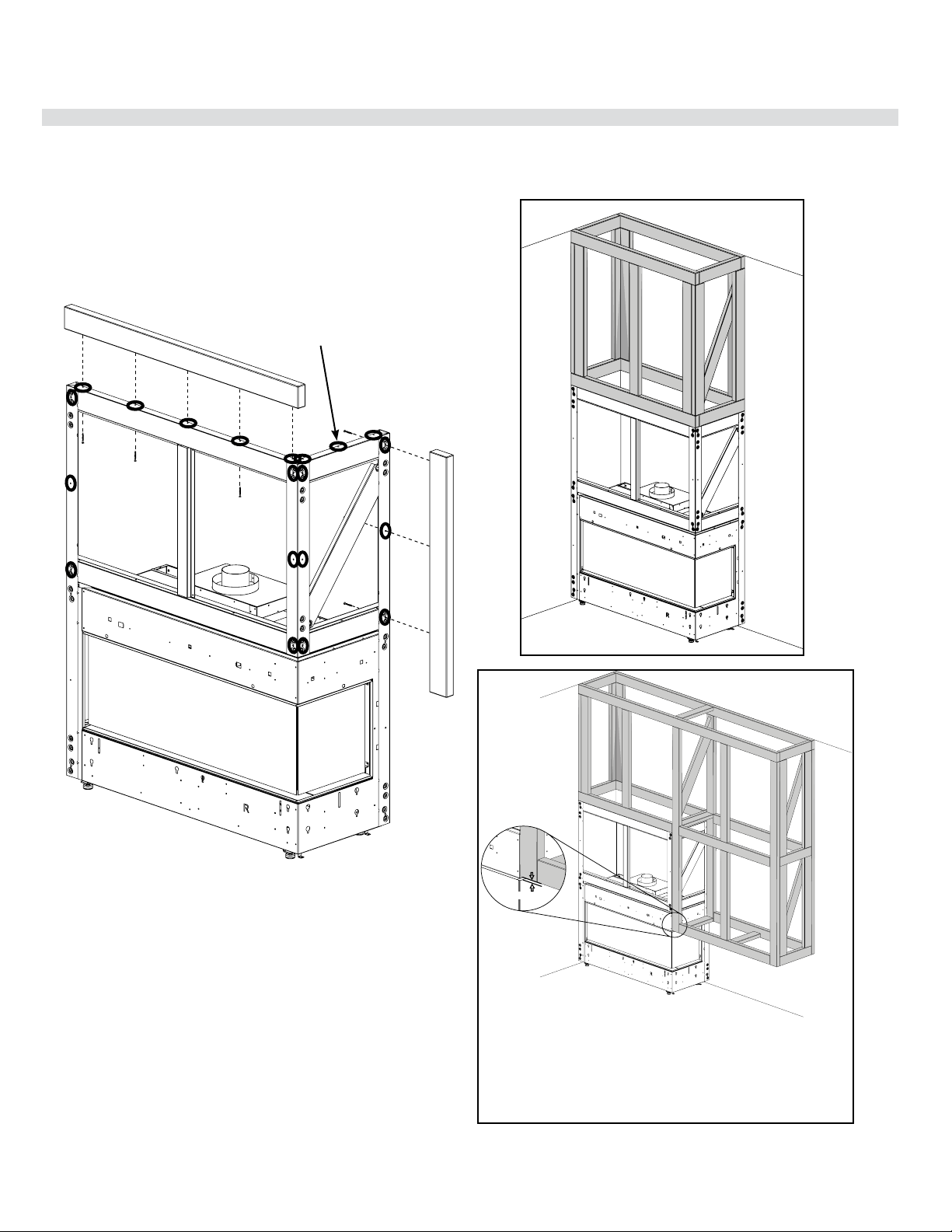
City Series CC40E-11 | 45
installation
Building Additional Framing Off of the Framing Kit
919-773a
04.24.17
Holes for fi xing additional
framing to kit
Potential Wood Framing installs
This framing kit is designed as a base in which to build additional
framing. Studs can be affi xed to all outer faces using the holes
identifi ed below. This will provide a stable surface that is fl ush with
the front of the fi replace, ready for drywall or other fi nishing material.
The framing must be strong enough to support the weight of all
fi nishing material and must not put any weight on the fi replace.
BUILDING FRAMING OFF OF THE KIT
1/2” for drywall
Leave gap between
framing and unit trim
for nishing material
4
CITY SERIES
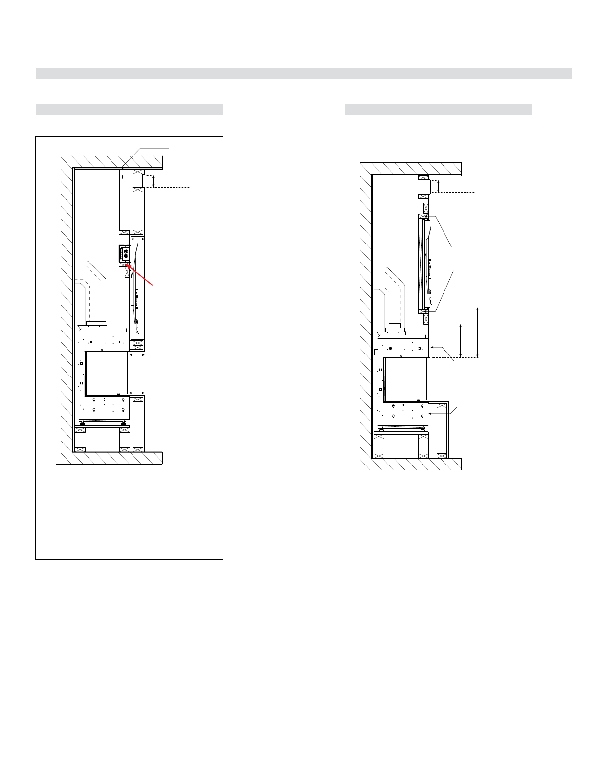
46 | City Series CC40E-11
installation
TV Recessed into Wall- Typical Installs
Maximum TV Recess TV Flush with Hearth
Max. 2 x 4 stud
Max. 2 x 4 stud
CB40 Typical Installs
MAXIMUM TV RECESS FLUSH TV WITH HEARTH
5/8”
4 (117 mm) maximum TV recess
using 1/2” (13 mm) drywall
Flush wall TV recess using 1/2" (13 mm) drywall
Max 36”
Hearth
1/8
Max 5 ”
Mantle
5/8
Max 4 ”
TV recess with drywall
up against unit
Max 3” (76 mm)
To Top of Enclosure
2
120in min
Chase vent opening
Header Stud
17.5
”
(445 mm)
min
12” min (305 mm)
Screws must not
penetrate unit more
than 1/2” (13 mm).
Adhere to “No Screw”
zones painted on unit.
Glue can be used
as an alternative.
Max 3” (76 mm)
To Top of Enclosure
2
120in min
Chase vent opening
(includes 1/2" drywall)
(117 mm)
(130 mm)
(914 mm)
Max. 2 x 4 stud
Max. 2 x 4 stud
CB40 Typical Installs
MAXIMUM TV RECESS FLUSH TV WITH HEARTH
5/8”
4 (117 mm) maximum TV recess
using 1/2” (13 mm) drywall
Flush wall TV recess using 1/2" (13 mm) drywall
Max 36”
Hearth
1/8
Max 5 ”
Mantle
5/8
Max 4 ”
TV recess with drywall
up against unit
Max 3” (76 mm)
To Top of Enclosure
2
120in min
Chase vent opening
Header Stud
17.5
”
(445 mm)
min
12” min (305 mm)
Screws must not
penetrate unit more
than 1/2” (13 mm).
Adhere to “No Screw”
zones painted on unit.
Glue can be used
as an alternative.
Max 3” (76 mm)
To Top of Enclosure
2
120in min
Chase vent opening
(includes 1/2" drywall)
(117 mm)
(130 mm)
(914 mm)
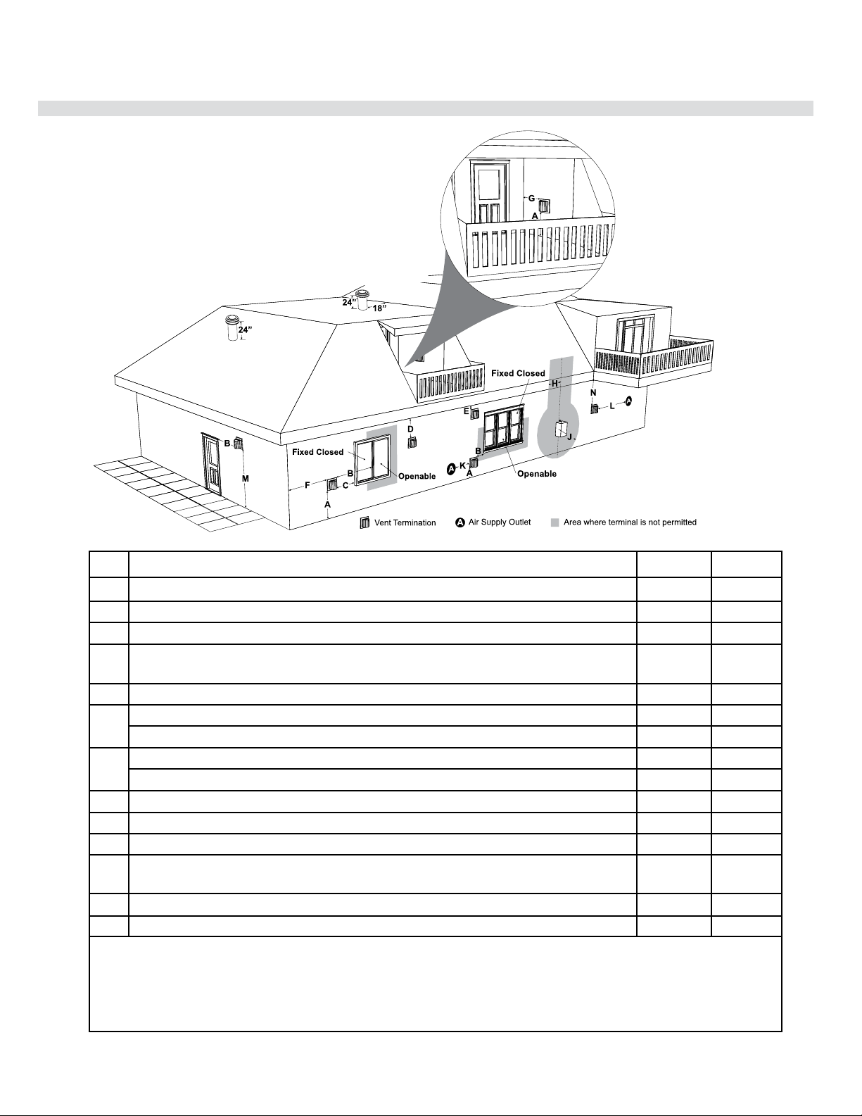
City Series CC40E-11 | 47
installation
Exterior Vent Termination Locations
Minimum Clearance Requirements
Canada
1
USA
2
A
Clearance above grade, veranda, porch, deck, or balcony 12"(30cm) 12"(30cm)
B
Clearance to window or door that may be opened 12"(30cm) 9" (23cm)
C
Clearance to permanently closed window * *
D
Vertical clearance to ventilated soffit located above the terminal within a horizontal distance of 2 feet (61cm)
from the center line of the terminal (check with the local code)
18"(46cm) 18"(46cm)
E
Clearance to unventilated soffit 20"(51cm) 20"(51cm)
F
Clearance to outside corner: with AstroCap Termination Cap. 6"(15cm) 6"(15cm)
Clearance to outside corner: with all other approved Termination Caps. 14"(36cm) 14"(36cm)
G
Clearance to inside corner: with AstroCap Termination Cap 6"(15cm) 6"(12cm)
Clearance to inside corner: with all other approved Termination Caps. 12"(30cm) 12"(30cm)
H
Clearance to each side of center line extended above meter/regulator assembly 36"(90cm)
a
*
J
Clearance to service regulator vent outlet 36"(90cm) *
K
Clearance to non-mechanical air supply inlet to building or the combustion air inlet to any other appliance 12"(30cm) 9" (23cm)
L
Clearance to a mechanical air supply inlet
#3' (91cm) above if within 10' (3m) horizontally.
72"(1.8m) 36"(90cm)
b
M
Clearance above paved sidewalk or a paved driveway located on public property 84"(2.1m)
┼
*
N
Clearance under veranda, porch, deck, or balcony 12"(30cm)
‡
*
1
In accordance with current CSA B149.1, Natural Gas and Propane Installation Code
2
In accordance with the current ANSI Z223.1/NFPA 54, National Fuel Gas Code
┼
A vent shall not terminate directly above a sidewalk or paved driveway which is located between two single family dwellings and serves both dwellings
‡ Permitted only if veranda, porch, deck, or balcony is fully open on a minimum of two sides beneath the floor
*
Clearance in accordance with local installation codes and the requirements of the gas supplier
a
3 feet (91cm) within a height of 15 feet (4.5m) above the meter / regulator assembly
b
3 feet (91cm) above - if within 10 feet (3m) horizontally
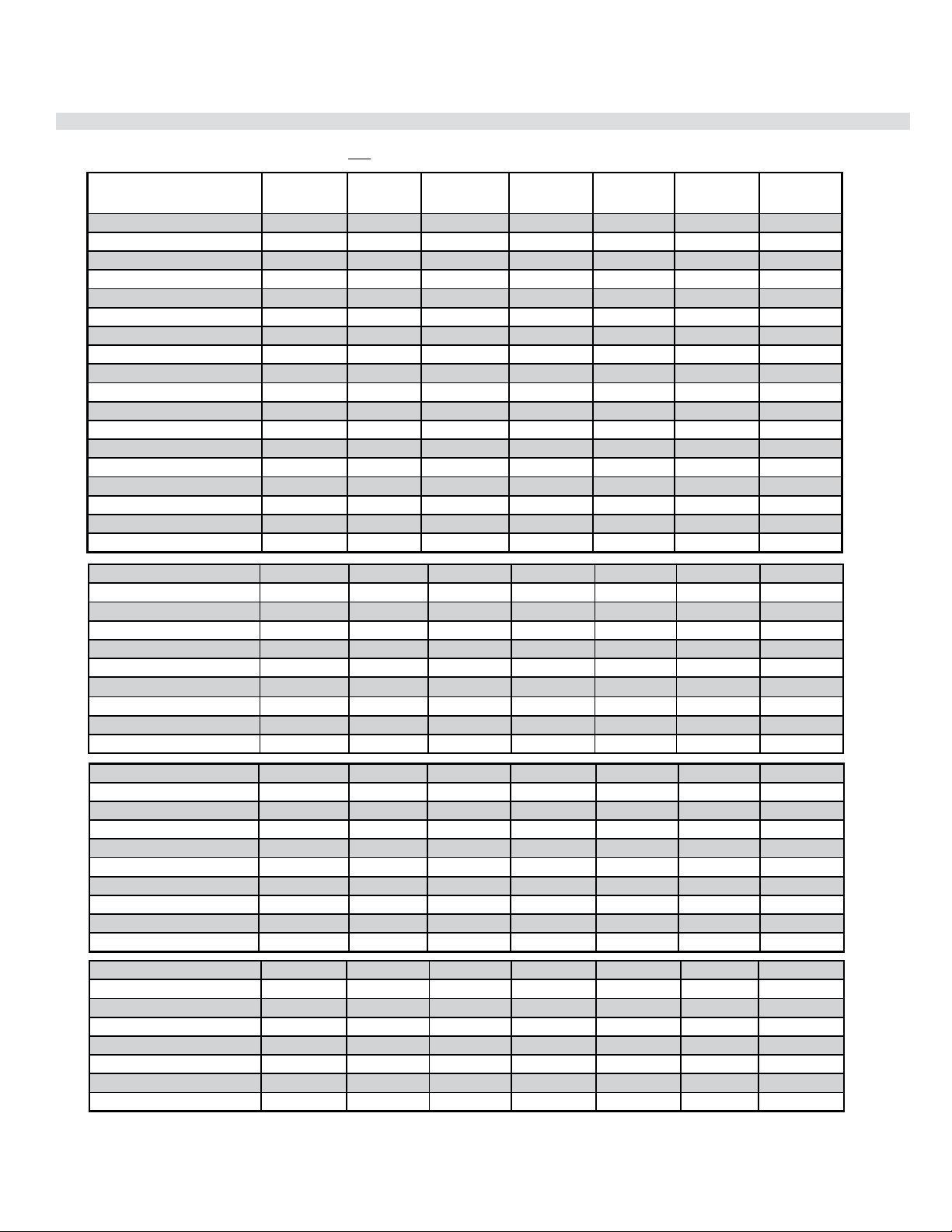
48 | City Series CC40E-11
installation
4” x 6-5/8” Rigid Pipe Cross Reference Chart
Components from different Manufacturers may not be mixed. Not All Rigid Pipe components are available directly from FPI.
* Olympia Ventis DV applicable for the following units only: B36XTE, B36XTCE, B41XTE, B41XTCE, P36, P36E
Description
Simpson
Direct Vent Pro
®
*Selkirk
Direct Temp™
*American Metal
Products®
Amerivent Direct
*Metal-Fab™
Sure Seal
*Security
Secure- Vent®
*ICC Excel
Direct
*Olympia
Ventis DV*
6" Pipe Length-Galvanized 46DVA-06 4DT-6 N/A 4D6 SV4L6 TC-4DL6 VDV-0406
6" Pipe Length-Black 46DVA-06B 4DT-6B N/A 4D6B SV4LB6 TC-4DL6B VDVB-0406
7" Pipe Length-Galvanized N/A N/A 4D7 N/A N/A N/A N/A
7" Pipe Length-Black N/A N/A 4D7B N/A N/A N/A N/A
9" Pipe Length-Galvanized 46DVA-09 4DT-9 N/A N/A N/A TC-4DL9 VDV-0409
9" Pipe Length-Black 46DVA-09B 4DT-9B N/A N/A N/A TC-4DL9B VDVB-0409
12" Pipe Length-Galvanized 46DVA-12 4DT-12 4D12 4D12 SV4L12 TC-4DL1 VDV-0412
12" Pipe Length-Black 46DVA-12B 4DT-12B 4D12B 4D12B SV4LB12 TC-4DL1B VDVB-0412
18" Pipe Length-Galvanized 46DVA-18 4DT-18 4D18 4D18 SV4LA TC-4DL18 VDV-0418
18" Pipe Length-Black 46DVA-18B 4DT-18B 4D18B 4D18B SV4LA TC-4DL18B VDVB-0418
24" Pipe Length-Galvanized 46DVA-24 4DT-24 4D24 4D24 SV4L24 TC-4DL2 VDV-0424
24" Pipe Length-Black 46DVA-24B 4DT-24B 4D24B 4D24B SV4LB24 TC-4DL2B VDVB-0424
36" Pipe Length-Galvanized 46DVA-36 4DT-36 4D36 4D36 SV4L36 TC-4DL3 VDV-0436
36" Pipe Length-Black 46DVA-36B 4DT-36B 4D36B 4D36B SV4LB36 TC-4DL3B VDVCB-0436
48" Pipe Length-Galvanized 46DVA-48 4DT-48 4D48 4D48 SV4L48 TC-4DL4 VDV-0448
48" Pipe Length-Black 46DVA-48B 4DT-48B 4D48B 4D48B SV4LB48 TC-4DL4B VDVB-0448
60" Pipe Length-Galvanized 46DVA-60 4DT-60 N/A N/A N/A N/A N/A
60" Pipe Length-Black 46DVA-60B 4DT-60B N/A N/A N/A N/A N/A
Adjustable Length 3"-10"-Galvanized N/A N/A N/A 4DAL N/A TC-4DLT N/A
Adjustable Length 3"-10"-Black N/A N/A N/A 4DALB N/A TC-4DLTB N/A
Adjustable Length 7"-Galvanized N/A N/A 4D7A N/A N/A N/A N/A
Adjustable Length 7"-Black N/A N/A 4D7AB N/A N/A N/A N/A
Extension Pipe 8-1/2"-Galvanized 46DVA-08A N/A N/A N/A N/A N/A N/A
Extension Pipe 8-1/2"-Black 46DVA-08AB N/A N/A N/A N/A N/A N/A
Adjustable Length 12"-Galvanized N/A N/A 4D12A N/A SV4LA12 TC-4dLSI N/A
Adjustable Length 12"-Black N/A N/A 4D12A N/A SV4LBA12 TC-4dLSIB N/A
Extension Pipe 16"-Galvanized 46DVA-16A N/A N/A N/A N/A N/A N/A
Extension Pipe 16"-Black 46DVA-16AB N/A N/A N/A N/A N/A N/A
45º Elbow-Galvanized 46DVA-E45 4DT-EL45 4D45L N/A N/A TE-4DE45 VDV-EL0445
45º Elbow-Black 46DVA-E45B 4DT-EL45B 4DT-EL45B N/A N/A TE-4DE45B VDVB-EL0445
45º Elbow Swivel-Galvanized See 46DVA-E45 N/A N/A 4D45L SV4E45 N/A N/A
45º Elbow Swivel-Black See 46DVA-E45B N/A N/A 4D45LB SV4EB45 N/A N/A
90º Elbow-Galvanized 46DVA-E90 4DT-EL90S 4DT-EL90S N/A N/A TE-4DE90 VDV-EL0445
90º Elbow-Black 46DVA-E90B 4DT-EL90SB 4DT-EL90SB N/A SV4EBR90-1 TE-4DE90B VDVB-EL0445
90º Elbow, Swivel-Galvanized See 46DVA-E90 N/A N/A 4D90L SV4E90-1 N/A N/A
90º Elbow, Swivel-Black See 46DVA-E90B N/A N/A 4D90LB SV4EB90-1 N/A N/A
90º Starter Elbow, Swivel-Galvanized
N/A N/A N/A 4D90A N/A N/A N/A
Adaptor* N/A N/A N/A 4D90L N/A N/A VDV-UAA04
4" X 6-5/8" RIGID PIPE CROSS REFERENCE CHART
Components from different Manufacturers may not be mixed. Not all rigid pipe components are available directly from Regency.
Note: The listed manufacturers may have other lengths not shown on this chart, which would also be approved.
Ceiling Support N/A 4DT-CS 4DSP 4DFSP SV4SD TM4-RDS VDV-SCR04
Cathedral Support Box 46DVA-CS 4DT-CSS 4DRSB 4DRS SV4CSB TM4-SDS VDV-CSS04
Wall Support/Band 46DVA-WS 4DT-WS/B 4DWS 4DWS SV4BM TM-SWS VDV-WS04
Offset Support 46DVA-ES
4DT-OS N/A N/A SV4SU TM-SOS N/A
Wall Thimble-Black 46DVA-WT 4DT-WT 4DWT 4DWT SV4RSM N/A VDV-WPT04
Wal
l Thimble Cover/Ceiling Support 46DVA-DC N/A N/A N/A SV4PF N/A N/A
Firestop Spacer 46DVA-FS 4DT-FS 4DFSP 4DFS SV4BF TM-4CS VDV-FS04
Trim Plate-Black N/A 4DT-TP 4DFPB 4DcP SV4LA TM-4TP VDV-WTC04
* Not available from Regency
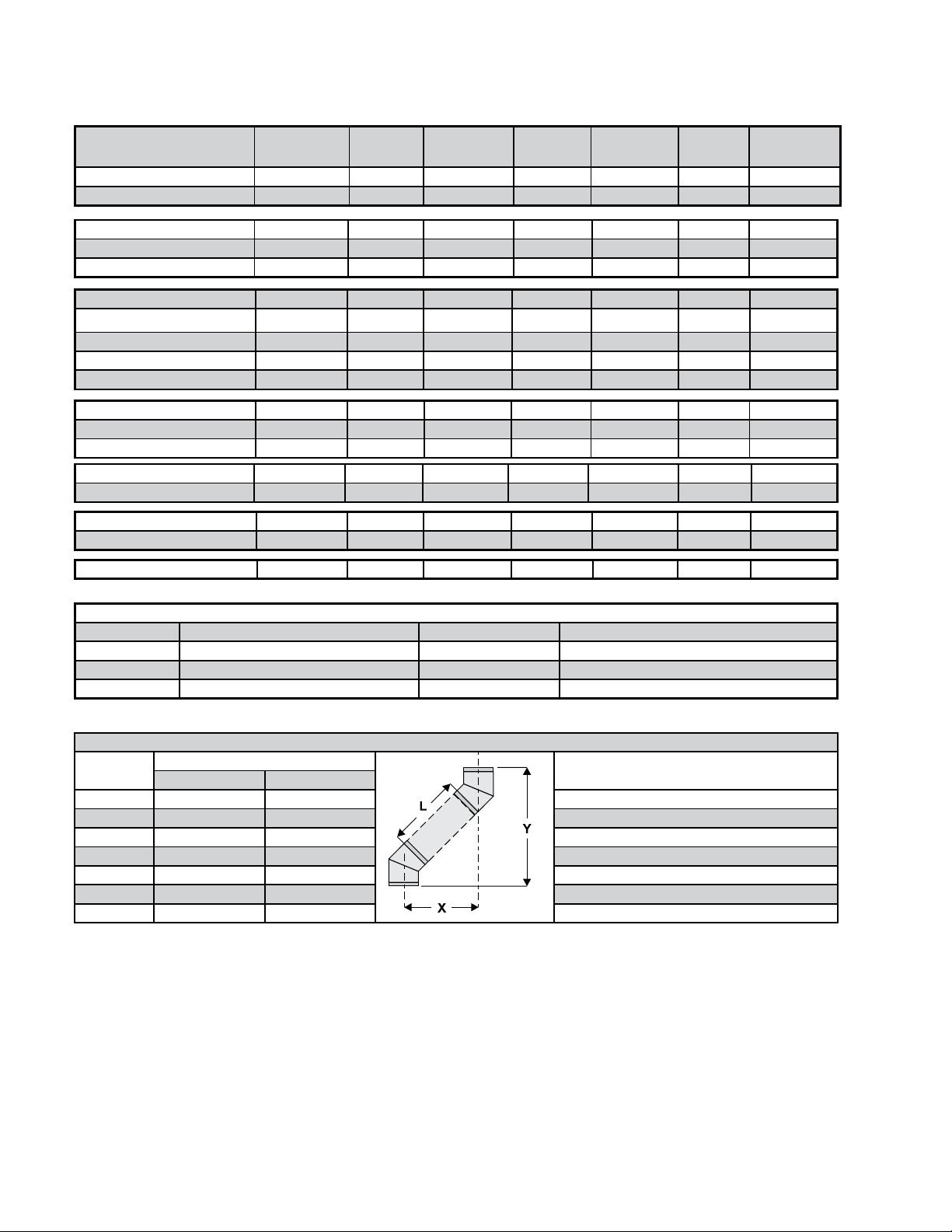
City Series CC40E-11 | 49
installation
Description
Simpson
Direct Vent Pro
®
*Selkirk
Direct Temp™
*American Metal
Products®
Amerivent Direct
*Metal-Fab™
Sure Seal
*Security
Secure- Vent®
*ICC Excel
Direct
*Olympia
Ventis DV*
Attic Insulation Shield 12" 46DVA-IS N/A 4DAIS12 DDIS SV4RSA N/A VDV-AIS04
Attic Insulation Shield - Cold Climates 36"
46DVA-KHA N/A 4DAIS12 N/A N/A TM-4AS N/A
Basic Horizontal Termination Kit (A) N/A 4DT-HKA 4DHTK2 4DHTKA SV-SHK TM4-HTK VDV-KW04
Horizontal Termination Kit (B) N/A 4DT-HKB 4DHTK1 4DHTKB SV-HK TM4-HTK VDV-K04
Vertical Termination Kit N/A 4DT-VKC 4DHTK 4DHTK SV-FK N/A N/A
High Wind Vertical Cap 46DVA-VCH N/A N/A N/A N/A TM-4VT VDV-VCHW04
High Wind Horizontal Cap N/A N/A N/A N/A N/A TM-4DHT N/A
Horizontal Square Termination Cap 46DVA-HC 4DT-HHC 4DHC 4DHT SV4CHC-1 TM-4HT VDV-HC04
Vertical Termination Cap 46DVA-VC 4DT-HVC 4DVC 4DVT SV4CGV-1 N/A N/A
Storm Collar 46DVA-SC 4DT-SC 4DSC 4DSC SV4FC TM-SC VDV-SC04
Wall Firestop 46DVA-WFS N/A N/A N/A N/A TM-4TR VDV-FS04
Flashing - Flat Roof 46DVA-FF N/A N/A N/A N/A N/A N/A
Adjustable Flashing 0/12-6/12 46DVA-F6 4DT-ST14 4D12S 4DF SV4STC14 TF-4FA VDV-F0406
Adjustable Flashing 6/12-12/12 46DVA-F12 4DT-ST36 4D36S 4DF12 SV4STC36 TF-4FB VDV-SSO
Vinyl Siding Standoff 46DVA-VSS 4DT-VS N/A 4DVS SV4VS TM-VSS N/A
Vinyl Siding Shield Plate N/A 4DT-VSP N/A N/A SV4VS N/A N/A
Snorkel Termination 14” 46DVA-SNK14 N/A N/A N/A N/A TM-4ST14 N/A
Snorkel Termination 36” N/A N/A N/A N/A N/A TM-4ST36 N/A
FPI
946-506/P Vent Guard (Optional) for AstroCap 946-205 Vinyl Siding Shield for Riser Vent Terminal
**510-994 Rigid Pipe Adaptor (Must use with all rigid piping) 946-208/P Vent Guard (Optional) for Riser Vent Terminal
640-530/P Riser Vent Terminal 946-523/P AstroCap Horizontal Cap
946-206 Vinyl Siding Standoff for AstroCap
Note: When using Metal-Fab Sure Seal Rigid Piping - please note that the Adaptor (4DDA) must be used in conjunction with FPI Rigid Pipe Adaptor (510-994).
Note: Horizontal runs of vent must be level, or have a 1/4” rise for every 1 foot of run towards the termination.
Never allow the vent to run downward - this could cause high temperatures and may present a possible fire hazard.
Offset Pipe Selection: Use this table to determine offset pipe lengths.
Pipe Length
(L)
4” x 6-5/8” Venting For specific instructions on venting components - visit the
manufacturers website listed below.
Run (X) Rise (Y)
0” (0mm) 4-7/8” (124mm) 13-7/8” (340mm) Simpson Direct Vent Pro: www.duravent.com
6” (152mm) 8” (203mm) 16-1/2” (419mm) Selkirk Direct-Temp: www.selkirkcorp.com
9” (229mm) 10-1/8” (257mm) 18-5/8” (473mm) American Metal Products: www.americanmetalproducts.com
12” (305mm) 12-1/4” (311mm) 20-3/4” (527mm) Metal-Fab Sure Seal: www.mtlfab.com
24” (610mm) 20-5/8” (524mm) 29-1/8” (740mm) Security Secure Vent: www.securitychimneys.com
36” (914mm) 29” (737mm) 37-1/2” (953mm) Industrial Chimney Company: www.icc-rsf.com
48” (1219mm) 37-7/16” (951mm) 45-15/16” (1167mm) Olympia Ventis DV: www.olympiachimney.com
* Not available from Regency
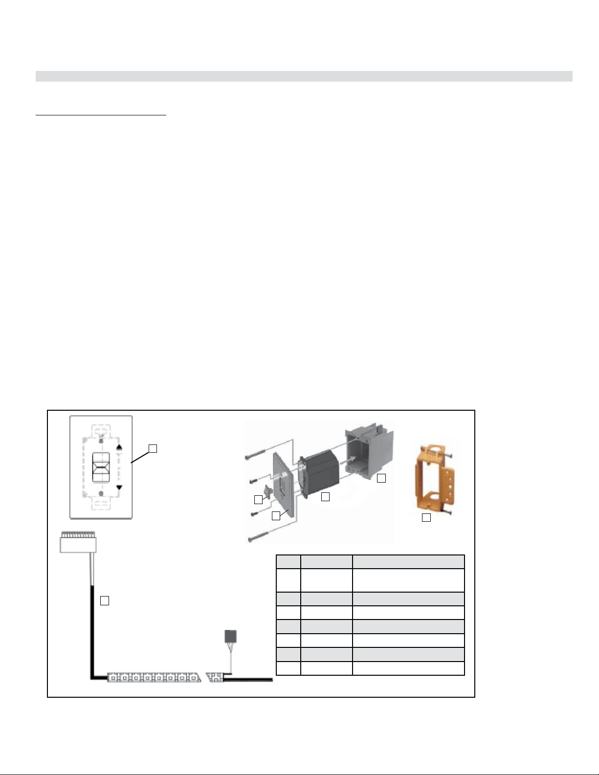
50 | City Series CC40E-11
installation
IMPORTANT INSTALLATION NOTE:
The battery holder must be placed inside the supplied (low voltage) junction type wall box and installed into
the wall only.
DO NOT INSTALL WITHIN THE CONFINES OF THE FIREPLACE
SWITCH MUST BE ACCESSIBLE
Battery Holder Installation
1. Install the low voltage junction box to the framing, at desired location within 11-1/2 ft. from fireplace.
2. Feed the 6 pin connector wiring harness through the opening at back of junction box. The wiring harness
is located on the right hand side and must be installed prior to finishing.
3. Connect the 6 pin connector to the back of the Battery Holder.
4. Install the Battery Holder in the Low Voltage Junction box.
5. Insert the 4 AA type batteries in the battery compartment with the correct polarity.
6. Place the slider into the cover plate.
7. Put the Battery Holder switch in the “OFF” position, to allow correct lineup for slider switch.
8. Make sure the Battery Holder and cover plate words “ON” and “UP” are on the same side.
9. Align the slider with the switch on the Battery Holder and couple the switch into the slider.
10. Align the screw holes.
11. Using the two (2) screws provided secure the cover plate to the Battery Holder.
12. For coding instructions, see full details in this manual.
Proflame Battery Holder
Wall Mount On / Off Switch and Battery Holder Installation
Required for all installations
ON
REMOTE
OFF
1
6
2
3
4
1
5
Item Part No. Description
1 N/A Slider Switch (included with
wall plate)
2 911-335 Wall Plate - White
911-343 Wall Plate - Black
3 911-337/P Battery Holder
4 N/A J-Box
5 910-369 Low Voltage Junction Box
6 911-181 Battery Holder Wire Harness
2
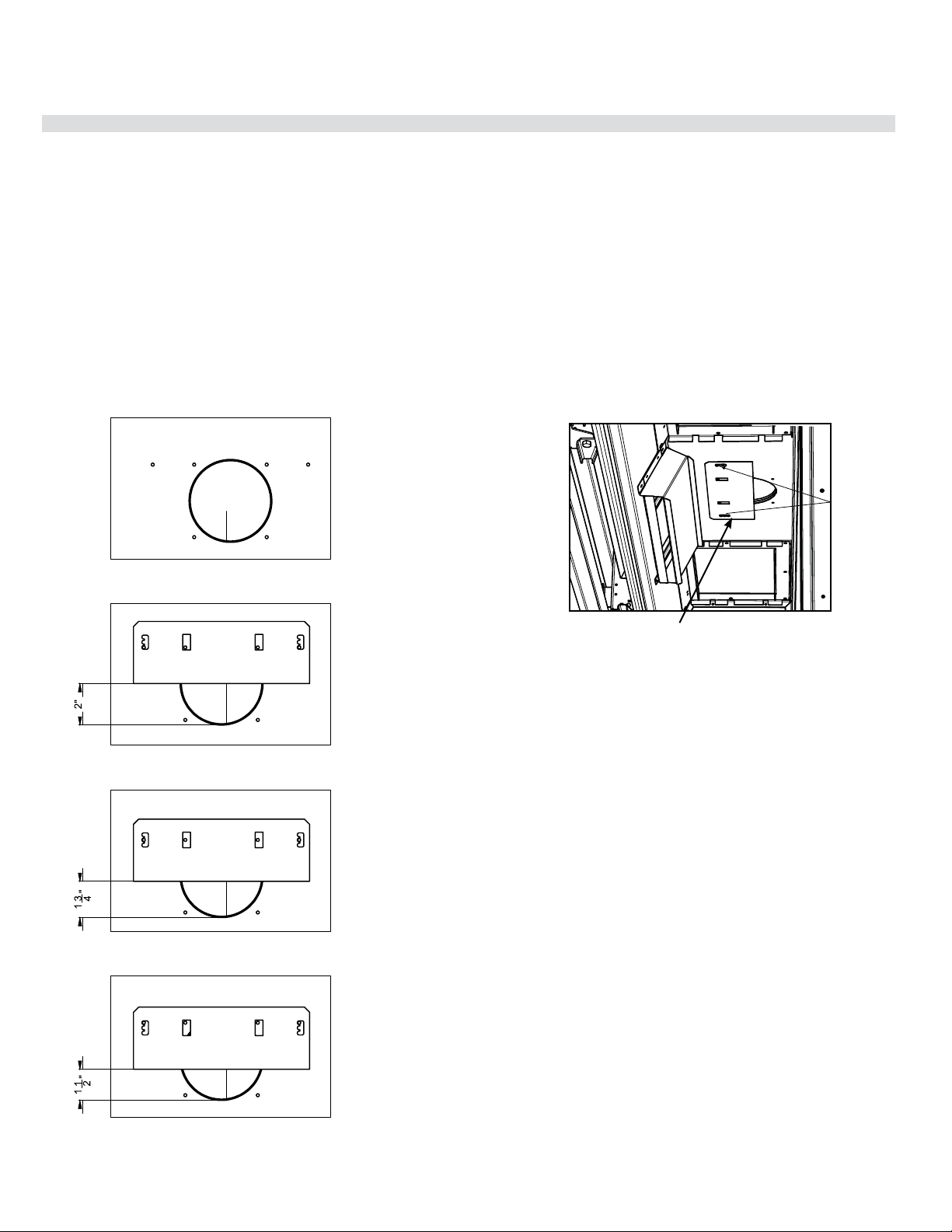
City Series CC40E-11 | 51
installation
Vent restriction is required for certain venting installations, see the diagrams in the "Venting
Arrangements" section to determine if they are required for your installation.
The Vent Restrictor plate is packed in the instruction manual package.
To set the vent restriction as indicated in the venting arrangements diagrams, refer to the following instructions;
1. Remove the safety glass and firebox glass - see instructions in this manual.
2. Remove the screws that hold the vent restrictor plate in place (see Diagram 1)
3. Adjust the vent restrictor plate to the required vent restrictor position as per the diagrams shown.
4. Once the vent restrictor plate is in the required position, secure with screws.
Vent Restrictor Position (Part # 656-017F)
Vent restrictor positions:
Set 0 (Full open) Factory set
Set 1 (Vent restrictor at 2”)
Set 2 (Vent restrictor at 1.75”)
Set 3 (Vent restrictor at 1.5”)
Vent restrictor location - inside top of firebox
Diagram 1
Screw
locations
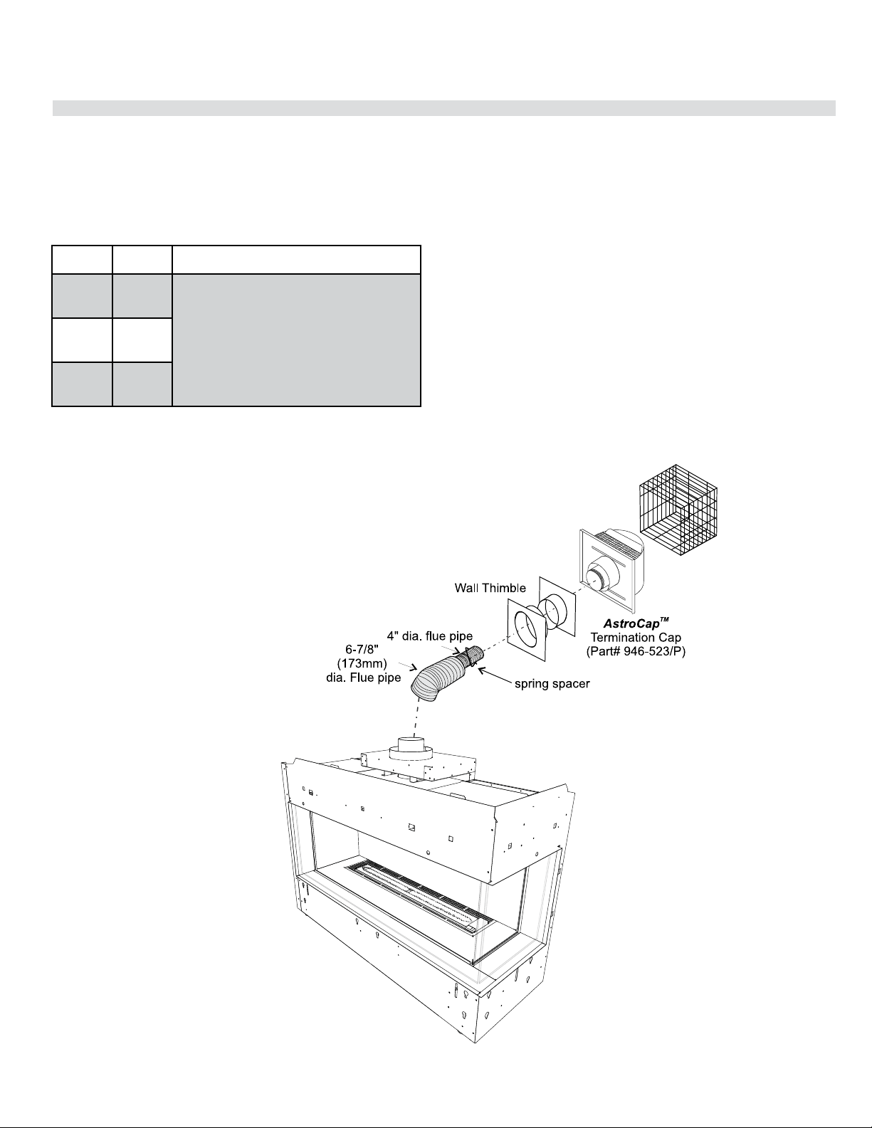
52 | City Series CC40E-11
installation
Vent Guard - if required*
(Part #946-506/P)
Notes:
1. Liner sections should be continuous without any joints
or seams.
2. Only Flex pipe purchased from Regency
®
may be used
for Flex installations
3. Horizontal vent must be supported every 3 feet.
4. Flex system can only be used up to a maximum
continuous vent length of up to 10 feet. If longer runs
are required, rigid pipe must be used.
Horizontal Terminations - Flex Vent 4" x 6-7/8"
These venting systems, in combination with the CC40LE/CC40RE Direct Vent Gas Fireplace, have been tested and listed as a direct vent heater system by
Intertek. The location of the termination cap must conform to the requirements in the Vent Terminal Locations diagram in "Exterior Vent Termination Locations"
section.
Regency
®
Direct Vent (Flex) System Termination Kits includes all the parts needed to install the CC40LE/CC40RE using a flexible vent.
FPI Kit # Length Contains:
#946-513 2 Feet 1. 6-7/8” flexible outer liner (Kit length)
2. 4” flexible inner liner (Kit length)
3. spring spacers
4. thimble
5. AstroCap termination cap
6. screws
7. tube of Mill Pac
8. plated screws
9. S.S. screws #8 x 1-1/2” drill point
#946-515 4 Feet
#946-516 10 Feet
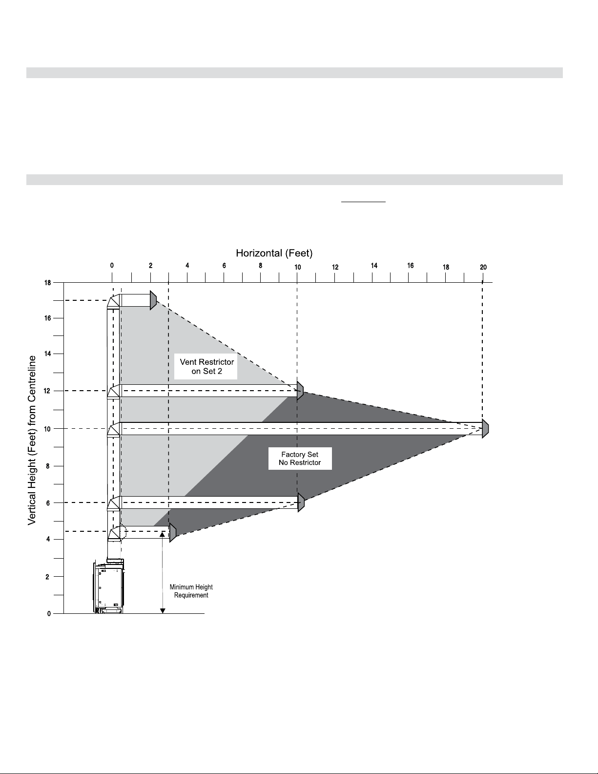
City Series CC40E-11 | 53
installation
Venting Introduction
The CC40LE/CC40RE uses the "balanced flue" technology Co-Axial system. The inner liner vents products of combustion to the outside while the outer
liner draws outside combustion air into the combustion chamber thereby eliminating the need to use heated room air for combustion and losing warm room
air up the chimney.
Note: These flue pipes must not be connected to any other appliance.
The gas appliance and vent system must be vented directly to the outside of the building, and never be attached to a chimney serving a separate solid fuel or
gas burning appliance. Each direct vent gas appliance must use it's own separate vent system. Common vent systems are prohibited.
Venting Arrangement for Horizontal Terminations
The diagram shows all allowable combinations of vertical runs with horizontal terminations, using one 90
o
(two 45
o
elbows equal one 90
o
elbow).
Note: When using rigid vent pie systems, the rigid pipe adapter (Part# 510-994) must be used in all applications.
• Maintain clearances to combustibles as listed in "Clearances" section
• Horizontal vent must be supported every 3 feet.
• Firestops are required at each floor level and whenever passing through a wall.
• A vent guard should be used whenever the termination is lower than the specified minimum or as per local codes.
• Flex system can only be used up to 10 feet - otherwise rigid venting must be used.
VENT RESTRICTOR SETTING:
Vent restrictor factory set at Set 0.
Refer to the "Vent Restrictor Position" section for details on how to change the vent restrictor from the factory setting of Set 0 to Set 2 if required.
NOTE: A minimum of 1' (305mm) vertical off the top of the unit is required before any horizontal runs can start.
Note: For horizontal terminations the Regency Direct Vent Flex System may be used for installations with a maximum continuous
vent length of up to 10 feet. If longer runs are required, rigid pipe must be used.
56-1/4” (1429mm)
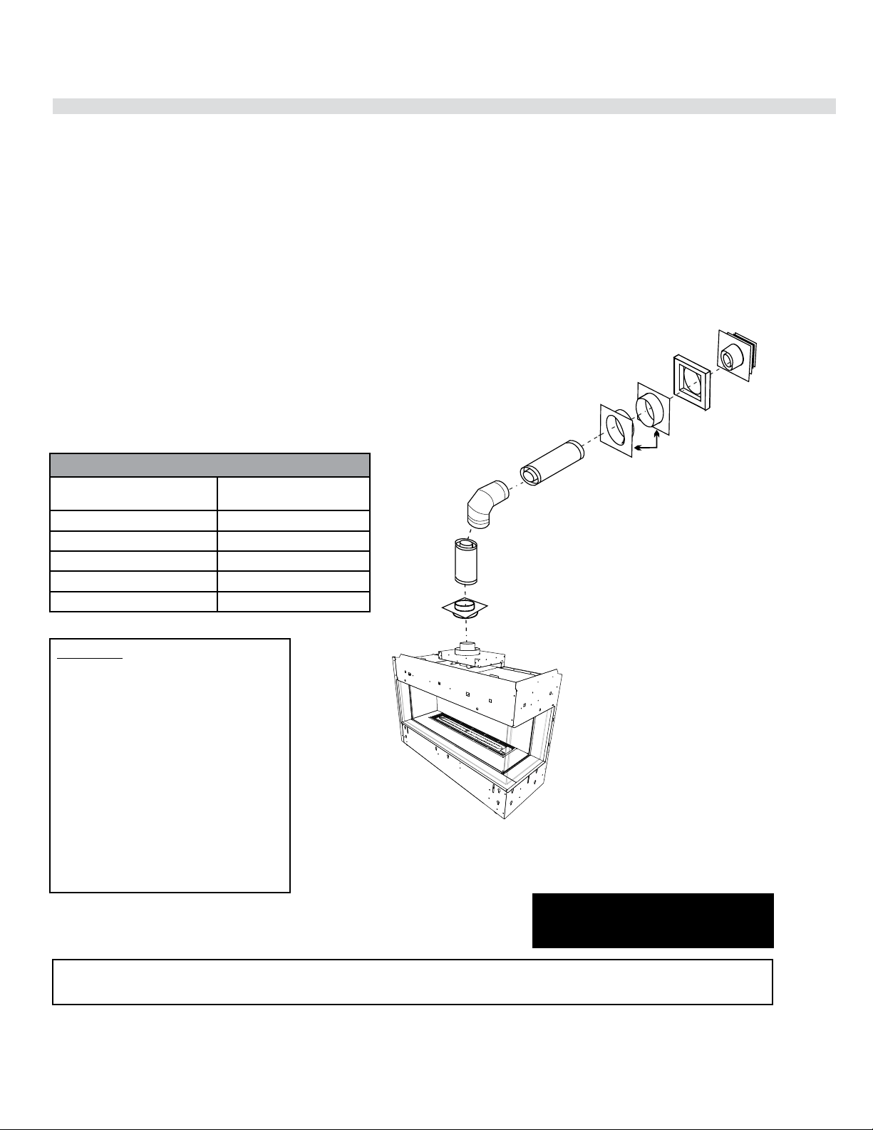
54 | City Series CC40E-11
installation
Horizontal Terminations - Rigid Pipe 4" x 6-5/8"
The minimum components required for a basic horizontal
termination are:
1 Horizontal Termination Cap
1 Rigid Pipe Adaptor (510-994)
1 Wall Thimble
1 Length of pipe to suit wall thickness
(see chart)
Wall thickness is measured from the back standoffs to the inside
mounting surface of termination cap. For siding other than vinyl
furring strips may be used instead of the vinyl siding standoff, to
create a level surface to mount the vent terminal. The Terminal
must not be recessed into siding. Measure the wall thickness
including furring strips.
If a Vinyl Siding Standoff is required (it must be used with vinyl
siding), measure to outside surface of wall without siding and
add 2 inches.
When using Rigid Vent other than
Simpson Dura-Vent, 3 screws must be
used to secure rigid pipe to adaptor.
This product has been evaluated by Intertek
for using a Rigid Pipe Adaptor in conjunction
with Duravent Direct-Vent, Selkirk Direct-Temp,
Ameri Vent Direct Venting, ICC Excel Direct,
Olympia Chimney and Security Secure Vent
systems. Use of these systems with the Rigid
Pipe adaptor is deemed acceptable and does
not affect the Intertek WHI listing of components.
WARNING:
Do not combine venting components from
different venting systems.
Use of the the AstroCap
TM
and FPI Riser is
acceptable with all systems.
The FPI AstroCap
TM
and FPI Riser Vent terminal are certified for installations using FPI venting systems as well as Simpson Dura-Vent
®
Direct Vent, American
Metal Products Ameri Vent Direct Vent, Security Secure Vent
®
, ICC Excel, Selkirk Direct-Temp and Olympia Chimney. AstroCap
TM
is a proprietary trade-
mark of FPI Fireplace Products International Ltd. Dura-Vent® and Direct Vent are registered and/or proprietary trademarks of Simpson Dura-Vent Co. Inc.
Flat Wall Installation
Wall Thickness
(inches)
Vent Length Required
(inches)
4" - 5-1/2" 6"
7" - 8-1/2" 9"
10" - 11-1/2" 12"
9" - 14-1/2' 11" - 14-5/8" Adj. Pipe
15" - 23-1/2" 17" - 24" Adj. Pipe
Pipe Length
Vertical Terminal
Storm Collar
Flashing
Ceiling Firestop
Adj.Pipe Length
Horizontal
Termination Cap
Wall Thimble
Vinyl Siding
Standoff (Optional)
Rigid Pipe Adapter
o
90 Elbow
Pipe Length
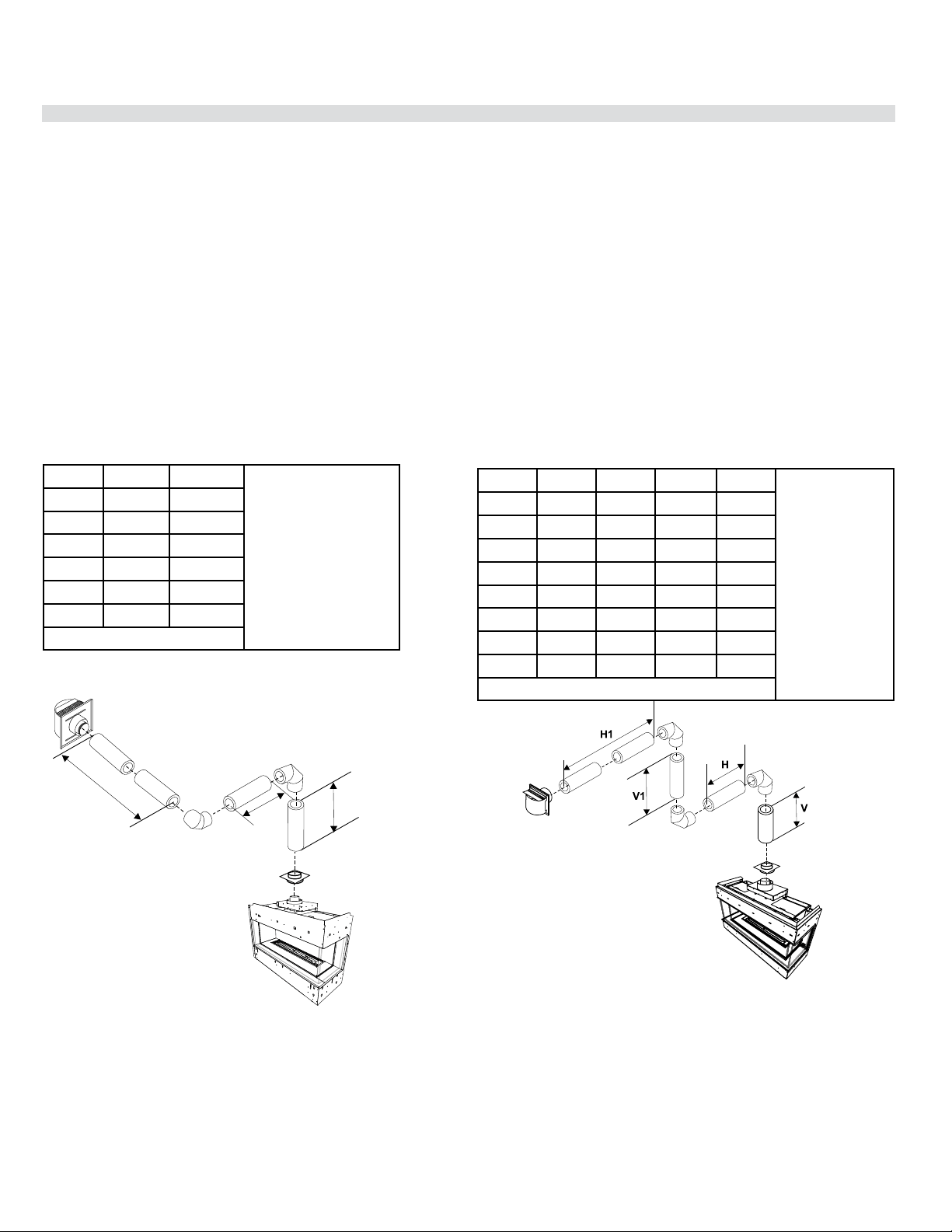
City Series CC40E-11 | 55
installation
Horizontal Terminations - Rigid Pipe 4" x 6-5/8"
The diagrams below show examples of horizontal termination arrangements using one, two, or three 90
o
elbows (two 45
o
elbows equal one 90
o
elbow)
1. A maximum of three 90
o
elbows are permitted.
2. Minimum distance between elbows is 1 ft. (305mm).
• Maintain clearances to combustibles as listed in the "Clearances" section.
• Horizontal vent must be supported every 3 feet.
• Firestops are required at each floor level and whenever passing through a wall.
• Must use optional rigid pipe adaptor (Part# 510-994) when using rigid pipe vent systems.
• A vent guard should be used whenever the termination is lower than the specified minimum or as per local codes.
• Flex system can only be used up to 10 feet - otherwise rigid venting must be used.
H
H1
V
Horizontal Venting with Two (2) 90
o
Elbows
One 90
o
elbow = Two 45
o
elbows.
Option V H + H1
With these options,
maximum total pipe length
is 30 feet with minimum
of 6 feet total vertical
and maximum 8 feet total
horizontal.
Please note minimum 1
foot between 90
o
elbows
is required.
A) 1' Min. 2' Max.
B) 2' Min. 4' Max.
C) 3' Min. 5' Max.
D) 4' Min. 6' Max.
E) 5' Min. 7' Max.
F) 6' Min. 8' Max.
Restrictor Set 0 - Factory Setting
Horizontal Venting with Three (3) 90
o
Elbows
One 90
o
elbow = Two 45
o
elbows.
Option V H V + V1 H + H1
With these options,
max. total pipe
length is 30 feet with
min. of 12 feet total
vertical and max. 9
feet total horizontal.
Please note min. 1
foot between 90
o
elbows is required.
A) 1' Min. 1' Max. 2' Min. 2' Max.
B) 1' Min. 2' Max. 3' Min. 3' Max.
C) 2' Min. 2' Max. 5' Min. 4' Max.
D) 3' Min. 2' Max. 7' Min. 5' Max.
E) 4' Min. 3 Max. 9' Min. 6' Max.
F) 5' Min. 4' Max. 10' Min. 7' Max.
G) 6' Min. 5' Max. 11' Min. 8' Max.
H) 7' Min. 6' Max. 12' Min. 9' Max.
Restrictor Set 0 - Factory Setting
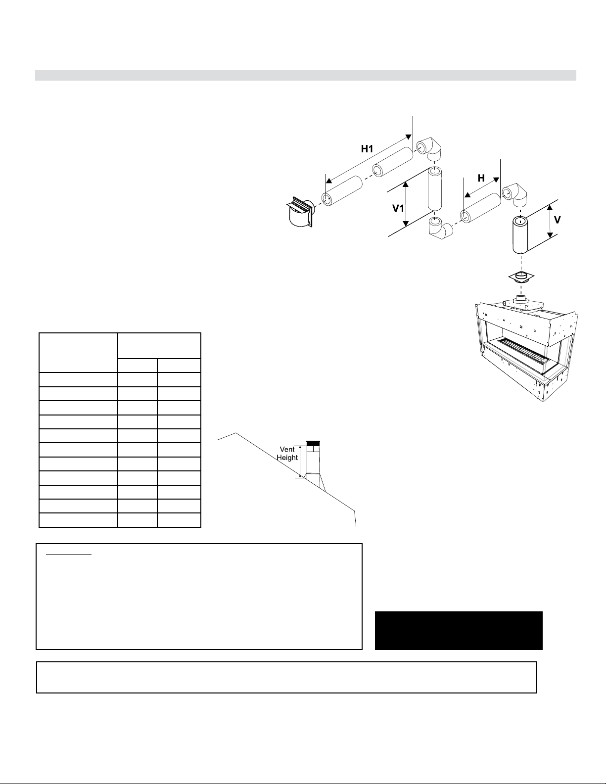
56 | City Series CC40E-11
installation
Vertical Terminations - Rigid Pipe 4" x 6-5/8"
The minimum components required for a basic vertical termination are:
1 Vertical Termination Cap
1 Rigid Pipe Adaptor (510-994)
1 Ceiling Firestop
1 Flashing
1 Storm Collar
1 Length of pipe to suit wall thickness
(see chart)
When using Rigid Vent other than
Simpson Dura-Vent, 3 screws must be
used to secure rigid pipe to adaptor.
This product has been evaluated by Intertek for using a Rigid Pipe Adaptor in conjunction
with Duravent Direct-Vent, Selkirk Direct-Temp, Ameri Vent Direct Venting, ICC Excel
Direct, Olympia Chimney, and Security Secure Vent systems. Use of these systems with
the Rigid Pipe adaptor is deemed acceptable and does not affect the Intertek WHI listing
of components.
WARNING:
Do not combine venting components from different venting systems.
Use of the the AstroCap
TM
and FPI Riser is acceptable with all systems.
The FPI AstroCap
TM
and FPI Riser Vent terminal are certified for installations using FPI venting systems as well as Simpson Dura-Vent
®
Direct Vent, American
Metal Products Ameri Vent Direct Vent, Security Secure Vent
®
, ICC Excel, Selkirk Direct-Temp and Olympia Chimney. AstroCap
TM
is a proprietary trade-
mark of FPI Fireplace Products International Ltd. Dura-Vent® and Direct Vent are registered and/or proprietary trademarks of Simpson Dura-Vent Co. Inc.
Galvanized pipe is desirable above the roofline due to its higher
corrosion resistance. Continue to add pipe sections through the
flashing until the height of the vent cap meets the minimum height
requirements specified in diagram 2 or local codes. Note that for
steep roof pitches, the vertical height must be increased. A poor
draft, or down drafting can result from high wind conditions near
big trees or adjoining roof lines, in these cases, increasing the
vent height may solve the problem.
Roof Pitch Minimum Vent
Height
Feet Meters
flat to 7/12 2 0.61
over 7/12 to 8/12 2 0.61
over 8/12 to 9/12 2 0.61
over 9/12 to 10/12 2.5 0.76
over 10/12 to 11/12 3.25 0.99
over 11/12 to 12/12 4 1.22
over 12/12 to 14/12 5 1.52
over 14/12 to 16/12 6 1.83
over 16/12 to 18/12 7 2.13
over 18/12 to 20/12 7.5 2.29
over 20/12 to 21/12 8 2.44
Diagram 2
Diagram 1

City Series CC40E-11 | 57
installation
Venting Arrangement for Vertical Terminations - Straight Vertical Venting and/or with a Max. of Two (2) 90
o
Elbows (1 - 90
o
= 2 - 45
o
)
The shaded area in the diagram shows all allowable combinations
of straight vertical and offset to vertical terminations, using two
90
o
elbows, with Rigid Pipe Venting Systems.
Two 45
o
elbows equal to one 90
o
elbow.
• Vent must be supported at offsets.
• Minimum distance between elbows is 1 ft. (305mm).
• Maintain clearances to combustibles as listed in the
"Clearances" section.
• Horizontal vent must be supported every 3 feet.
• Firestops are required at each floor level and whenever
passing through a wall.
• Must use optional rigid pipe adaptor (Part# 510-994) when
using rigid pipe vent systems.
• Refer to the "Vent Restrictor Position" section for details on
how to change the vent restrictor from the factory setting
of Set 0 through to Set 3 if required.
Maximum: 37 ft. (11.2m)
Minimum
8’6” (2.6m)
Min. 56-1/4”
(1429mm)
*Minimum length of pipe
between elbows 12” (305mm)
Maximum: 27 ft. (8.2m)
0
0
2
2
4
4
6
6
4
4
0
0
8
8
1
1
0
0
1
1
2
2
1
1
4
4
1
1
6
6
1
1
8
8
2
2
0
0
2
2
2
2
2
2
4
4
2
2
6
6
2
2
8
8
3
3
0
0
Vertical Height (Feet)
3
3
2
2
3
3
4
4
3
3
6
6
3
3
8
8
6
6
8
8
Horizontal (Feet)
2
2
0
0
4
4
1
1
0
0
1
1
2
2
1
1
6
6
1
1
8
8
1
1
4
4
2
200
Vent Restrictor on Set 2
Vent Restrictor on Set 3
Vent Restrictor on Set 1
*
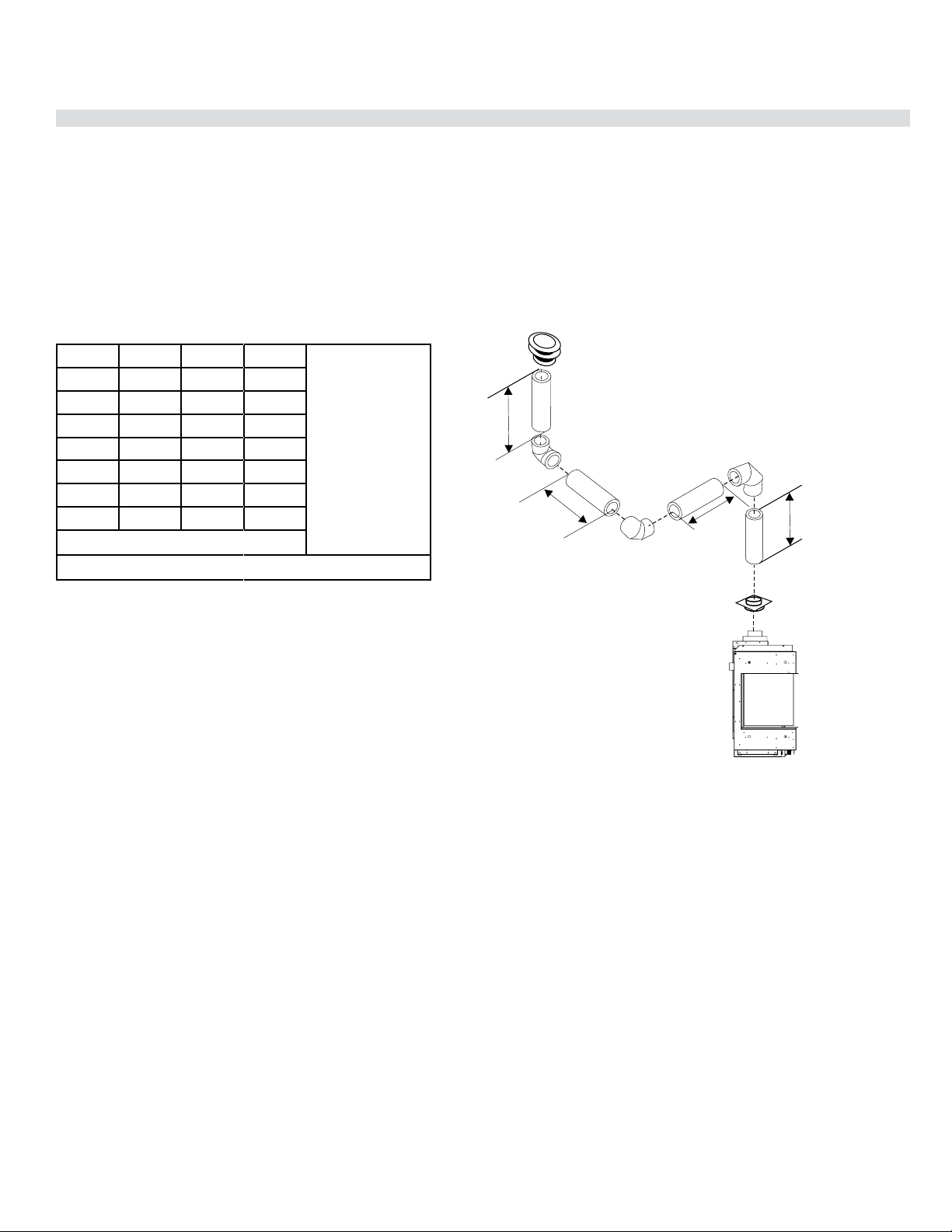
58 | City Series CC40E-11
installation
Vertical Terminations - Rigid Pipe 4" x 6-5/8"
• Two 45
o
elbows equal to one 90
o
elbow. Maximum of six 45
o
elbows allowed.
• Vent must be supported at offsets.
• Minimum distance between elbows is 1 ft. (305mm).
• Maintain clearances to combustibles as listed in the "Clearances" section.
• Horizontal vent must be supported every 3 feet.
• Firestops are required at each floor level and whenever passing through a wall.
• Must use optional rigid pipe adaptor (Part# 510-994) when using rigid pipe vent systems.
Vertical Venting with Three (3) 90
o
Elbows
One 90
o
elbow = Two 45
o
elbows.
V
H1
H
V1
Option V H + H1 V + V1
With these options,
max. total pipe length
is 30 feet with min. of
10 feet total vertical
and max. 8 feet total
horizontal.
Please note min. 1
foot between 90
o
elbows is required.
A) 1' Min. 2' Max 3' Min.
B) 2' Min. 3' Max 4' Min.
C) 3' Min. 4' Max 6' Min.
D) 4' Min. 5' Max 7' Min.
E) 5' Min. 6' Max 8' Min.
F) 6' Min. 7' Max 9' Min.
G) 7' Min. 8' Max 10' Min.
Lengths do not include elbow indicated
Restrictor Set 0 - Factory Setting
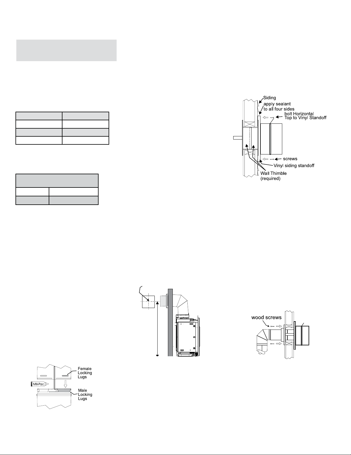
City Series CC40E-11 | 59
installation
C
L
C
L
56-1/4" (1429mm)
Min. height
(Rigid)
center
of hole
Diagram 4
Diagram 3
7. Ensure that the pipe clearances to combustible
materials are maintained (Diagram 3). Install
the termination cap.
Note: If installing termination on a vinyl
siding covered wall, a vinyl siding
standoff or furring strips must be
used to ensure that the termination
is not recessed into the siding.
The four wood screws provided should be
replaced with appropriate fasteners for stucco,
brick, concrete, or other types of sidings.
8. Before connecting the horizontal run of vent pipe
to the vent termination, slide the Wall Thimble
over the vent pipe. The wall thimble is required
for all horizontal terminations.
9. Slide the appliance and vent assembly towards
the wall carefully inserting the vent pipe into the
vent cap assembly. It is important that the vent
pipe extends into the vent cap sufficient distance
so as to result in a minimum pipe overlap of
1-1/4 inches (32mm). Secure the connection
between the vent pipe and the vent cap.
10. Install wall thimble in the center of the framed
hole and attach with wood screws (Diagram 4).
Install the vent system according to the manufacturer's
instructions included with the components.
1. Set the unit in its desired location. Check to
determine if wall studs or roof rafters are in the
way when the venting system is attached. If this
is the case, you may want to adjust the location
of the unit. Rough in the gas preferably on the
right side of the unit and the electrical (junction
block is on the left side) on the left.
2. Direct Vent pipe and fittings are designed with
special twist-lock connections to connect the
venting system to the appliance flue outlet. A
twist-lock appliance adaptor is required.
3. In conjunction with the Approved Vent system,
install the adaptor after the unit is set in its
desired location. Put a bead of Mill-Pac inside
the outer section of the adapter and a bead of
Mill-Pac on the inner collar. Slip the adapter over
the existing inner and outer flue collar. Fasten to
the outer collar only with the 3 supplied screws
(drilling pilot holes will make this easier).
4. Level the fireplace and fasten it to the framing
using nails or screws through the top and side
nailing strips.
Diagram 1
Note: For best results and optimum
performance with each approved
venting system, it is highly
recommended to apply Mill-Pac
sealant (supplied) to every inner
pipe connection. Failure to do
so may result in drafting or
performance issues not covered
under warranty.
Diagram 2
Horizontal runs of vent must be supported every
3 feet (0.9meter). Wall straps are available for
this purpose.
6. Mark the wall for a square hole.-see chart to left
for size. The center of the square hole should line
up with the center-line of the horizontal pipe. Cut
and frame the square hole in the exterior wall
where the vent will be terminated. See diagram
2 for center line requirements.
If the wall being penetrated is constructed of
non-combustible material, i.e. masonry block
or concrete, an 8" (203mm) diameter hole is
acceptable.
Note:
a) The horizontal run of vent must be level, or
have a 1/4 inch rise for every 1 foot of run
towards the termination. Never allow the
vent to run downward. This could cause
high temperatures and may present the
possibility of a fire.
b) The location of the horizontal vent
termination on an exterior wall must meet
all local and national building codes.
5. Assemble the desired combination of pipe and
elbows to the appliance adaptor and twist-lock
for a solid connection.
Recommended Framed Opening
Size
Vent Size Framing Size
4" x 6 - 5/8" 10" x 10"
Horizontal Top 3" (76mm)
Horizontal Side 2 " (51mm)
Horizontal Bottom 2" (51mm)
Vertical Vent 2" (51mm)
Minimum Vent Clearances
to Combustibles
Horizontal Termination - 4" x
6-5/8" Venting (Rigid Vent Sys-
tems)
Below are the recommended framing dimensions
(inside measurements) for the 4" x 6-5/8" rigid
vent terminations - for use with a firestop or wall
thimble.
Clearances noted below must be maintained; except
when passing through a wall, ceiling or at the termination
where the use of a firestop or wall thimble reduces
clearance to 1-1/2" (38mm).

60 | City Series CC40E-11
installation
Outside Wall
Mur extérieur
Furring
Strips
Fourrures en bois
Furstrp.eps
see also c34020a.eps
furstrpf.eps
french
1. Locate the unit in the framing, rough in the gas
(preferably on the right side of the unit). Locate
the centerline of the termination and mark wall
accordingly. Cut an square hole in the wall - see
chart (inside dimension).
Note: If installing termination on a siding covered
wall, a vinyl siding standoff or vinyl furring
strips must be used to ensure that the
termination is not recessed into the siding.
2. Level the fireplace and fasten it to the framing
using nails or screws through the nailing strips.
3. Assemble the vent assembly by applying Mill
Pac to the inner flue collar of the termination and
slipping the inner flex liner over it at least 1-3/8"
(35mm). Fasten with the 3 screws (drilling pilot
holes will make this easier). Apply Mill-Pac to
the outer flex pipe and slip it over the outer flue
collar of the vent terminal at least 1-3/8"(35mm)
and fasten with the 3 screws.
11”
11”
(294mm)
(294mm)
ASTROCAP
DIMENSIONS (946-523/P)
Minimum Vent Clearances
to Combustibles
Horizontal Termination - 4" x
6-5/8" Venting (Flex Vent Sys-
tems)
NOTE: Horizontal sections must be sup-
ported at intervals not exceeding
3 feet (0.9 meter). (Flame picture
and performance will be affected
by sags in the liner).
4. Separate the 2 halves of the wall thimble and
securely fasten the one with the tabs to the
outside wall making sure that the tabs are on
top and bottom. Fasten the other thimble half
to the inside wall. The thimble halves slip inside
each other and can be adjusted for 2 x 4 or 2
x 6 walls.
5. Slip the assembled liner and termination as-
sembly through the thimble making sure the
termination cap faces up (there are markings
on the cap indicating which way is up). This will
position the termination cap with proper down
slope for draining water. Fasten the cap to the
outer wall with the 4 supplied screws.
6. Pull the centre inner and outer flex liner out
enough to slip over the flue collars of the fire-
place. (You may wish to cut the liner shorter
to make it more workable.) Do not bend liner
more than 90o. The liners must slip over the
collars a minimum of 1-3/8".
7. Apply Mill Pac over the fireplace inner flue
collar and slip the inner flex liner down over it
and attach with 3 supplied screws.
8. Do the same with the outer flue collar and outer
flex liner.
9. Apply a bead of silicone between the thimble
and termination and around the outer edge of
the terminal at the wall in order to keep the
water out.
IMPORTANT: Do not locate termination hood
where excessive snow or ice buildup may
occur. Be sure to check vent termination
area after snow falls, and clear to prevent
accidental blockage of venting system. When
using snow blowers, make sure snow is not
directed towards vent termination area.
Clearances noted below must be maintained;
except when passing through a wall, ceiling or at
the termination where the use of a firestop or wall
thimble reduces clearance to 1" (25mm).
Recommended Framed Opening
Size
Vent Size Framing Size
4" x 6 - 5/8" 10" x 10"
Below are the recommended framing dimensions
(inside measurements) for the 4" x 6-5/8" rigid
vent terminations - for use with a firestop or wall
thimble.
Horizontal Top 3" (76mm)
Horizontal Side 2 " (51mm)
Horizontal Bottom 2" (51mm)
Vertical Vent 2" (51mm)
Termination
Cap
Wall Thimble 2 pieces
(10" (254mm)
Outer Diameter)
2” x 4” or 2” x 6”
6-7/8" (173mm)
dia. air intake
4" (102mm) dia. flue pipe
with spring spacer
Screws
(3 per
connection)
Screws
(4 per
connection)
C
L
56-1/4”
(1429mm)
Min.
of hole
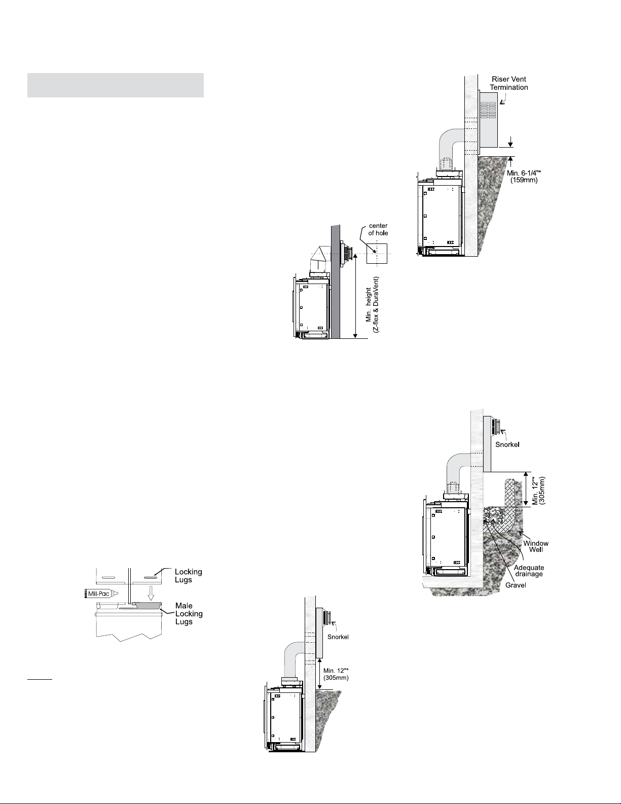
City Series CC40E-11 | 61
installation
56-1/4” (1429mm)
Diagram 4
6) The arrow on the vent cap should be
pointing up. Insure that the 1-1/2" clearances to
combustible materials are maintained (Diagram
4). Install the termination cap.
The four wood screws provided should be
replaced with appropriate fasteners for stucco,
brick, concrete, or other types of sidings.
NOTE: For Snorkel terminations in
ABOVE grade installations,
follow national or local code
requirements.
Below Grade Installation
If the Snorkel Termination must be installed below
grade, i.e. basement application, proper drainage
must be provided to prevent water from entering
the Snorkel Termination. Refer to Diagram 4. Do
not attempt to enclose the Snorkel within the wall,
or any other type of enclosure.
*Diagrams 3 & 4: As specified in CGA B149
Installation Code. Local codes or regulations
may require different clearances.
Dura-Vent Horizontal Termina-
tions
Install the vent system according to the
manufacturer's instructions included with the
components.
1) Set the unit in its desired location. Check to
determine if wall studs or roof rafters are in
the way when the venting system is attached.
If this is the case, you may want to adjust the
location of the unit. Rough in the gas preferably
on the right side of the unit and the electrical
(junction block is on the left side) on the left.
2) Direct Vent pipe and fittings are designed with
special twist-lock connections to connect the
venting system to the appliance flue outlet. A
twist-lock appliance adaptor is an available
option that must be used in conjunction with
the Simpson Dura-Vent Direct Vent system.
3) Put a bead of Mill-Pac inside the outer section
of the adaptor and on the inner collar. Slip the
adapter over the existing inner and outer flue
collar and fasten to the outer collar only with
the 3 supplied screws (drilling pilot holes will
make this easier). Level the fireplace and fasten
it to the framing using nails or screws through
the nailing strips.
4) Assemble the desired combination of pipe and
elbows to the appliance adaptor and twist-lock
for a solid connection.
Note: a) Twist-lock procedure: Four indentations,
located on the female ends of pipes and
fittings, are designed to slide straight onto
the male ends of adjacent pipes and fittings,
by orienting the four pipe indentations so
they match and slide in to the four entry slots
on the male ends, Diagram 1. Push the pipe
sections completely together, then twist-
lock one section clockwise approximately
one-quarter turn, until the two sections
are fully locked. The female locking lugs
will not be visible from the outside, on the
Black Pipe or fittings. They may be located
by examining the inside of the female ends.
Diagram 1
b) Horizontal runs of vent must be supported
every three feet. Wall straps are available
for this purpose.
5) Mark the wall for a 10" x 10" square hole. The
center of the square hole should line up with
the centerline of the horizontal pipe. Cut and
frame the 10 inch square hole in the exterior
wall where the vent will be terminated. If the
wall being penetrated is constructed of non-
combustible material, i.e. masonry block or
concrete, a 7"(178mm) dia. (7-1/2"(191mm)
dia. for flex) hole is acceptable.
Diagram 2
Note:
a) The horizontal run of vent must be level, or
have a 1/4 inch rise for every 1 foot of run
towards the termination. Never allow the
vent to run downward. This could cause
high temperatures and may present the
possibility of a fire.
b) The location of the horizontal vent
termination on an exterior wall must meet all
local and national building codes, and must
not be blocked or obstructed. For External
Vent Terminal Locations, see the "Exterior
Vent Termination Locations" section.
c) Snorkel Terminations:
For installations requiring a vertical rise on
the exterior of the building, 14-inch and 36-
inch tall Snorkel Terminations are available,
as well as the standard Riser Vent. Follow
the same installation procedures as used
for standard Horizontal Termination. NEVER
install the snorkel upside down.
Diagram 3a
Note: Riser Vent is
only for use in above
grade terminations.
NOTE: For best results and optimum perfor-
mance with each approved venting system, it is
highly recommended to apply “Mill-Pac” sealant
(supplied) to every inner pipe connection. Failure
to do so may result in drafting or performance
issues not covered under warranty.
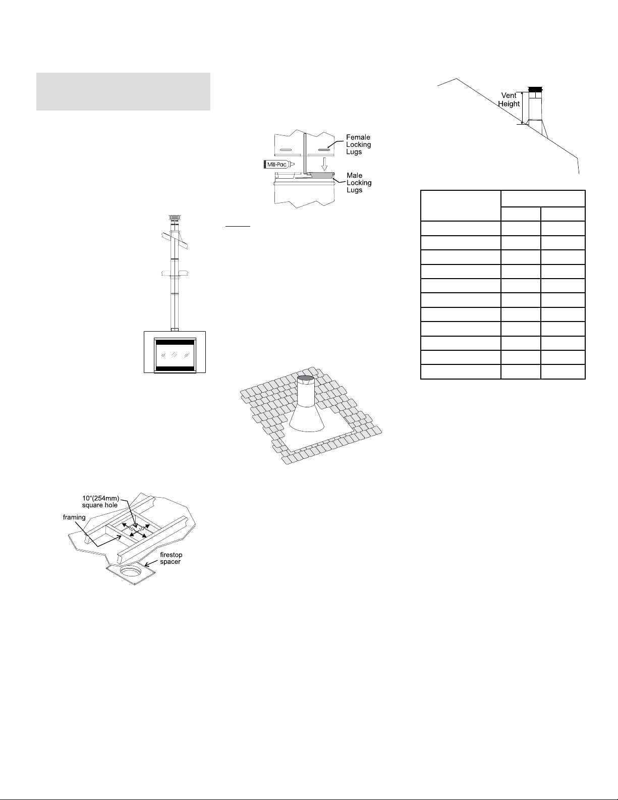
62 | City Series CC40E-11
installation
Diagram 4
Diagram 3: The upper half of the ashing is installed
under the roong material and not nailed down
until the chimney is installed. This allows for small
adjustments.
Diagram 2
Diagram 3
Dura Vent Vertical Termination
- 4" x 6-5/8" Venting (Rigid Vent
Systems)
1. Maintain the 1-1/2" clearances (air spaces) to
combustibles when passing through ceilings,
walls, roofs, enclosures, attic rafter, or other
nearby combustible surfaces. Do not pack
air spaces with insulation. Check "Venting"
Sections for the maximum vertical rise of the
venting system and the maximum horizontal
offset limitations.
2. Set the gas appliance in its desired location.
Drop a plumb bob down from
the ceiling to the position of
the appliance flue exit, and
mark the location where the
vent will penetrate the ceiling.
Drill a small hole at this point.
Next, drop a plumb bob from
the roof to the hole previously
drilled in the ceiling, and mark
the spot where the vent will
penetrate the roof.
3. A firestop spacer must
be installed in the floor or
ceiling of every level. To
install the Firestop spacer
in a flat ceiling or wall, cut a
10 inch square hole. Frame the hole as shown
in Diagram 2 and install the firestop.
NOTE: For best results and optimum perfor-
mance with each approved venting system, it is
highly recommended to apply “Mill-Pac” sealant
(supplied) to every inner pipe connection. Failure
to do so may result in drafting or performance
issues not covered under warranty.
4. Assemble the desired lengths of pipe and
elbows. Ensure that all pipes and elbow con-
nections are in the fully twist-locked position
and sealed.
5. Cut a hole in the roof centered on the small
drilled hole placed in the roof in Step 2. The hole
should be of sufficient size to meet the minimum
requirements for clearance to combustibles
of 1-1/2". Slip the flashing under the shingles
(shingles should overlap half the flashing) as
per Diagram 3.
6. Continue to assemble pipe lengths.
Note: If an offset is necessary in the attic
to avoid obstructions, it is important
to support the vent pipe every 3 feet,
to avoid excessive stress on the
elbows, and possible separation.
Wall straps are available for this
purpose.
Galvanized pipe is desirable above the roofline
due to its higher corrosion resistance. Continue
to add pipe sections through the flashing until the
height of the vent cap meets the minimum height
requirements specified in Dia. 4 or local codes.
Note that for steep roof pitches, the vertical
height must be increased. A poor draft, or down
drafting can result from high wind conditions
near big trees or adjoining roof lines, in these
cases, increasing the vent height may solve
the problem.
7. Ensure vent is vertical and secure the base of
the flashing to the roof with roofing rails, slide
storm collar over the pipe section and seal with
a mastic.
8. Install the vertical termination cap by twist-
locking it.
Note: Any closets or storage spaces, which
the vent passes through must be
enclosed.
Diagram 1
Note: All vertical terminations are vented
using 4" x 6-5/8" venting and rigid pipe
adaptor #510-994.
Roof Pitch Minimum Vent Height
Feet Meters
flat to 7/12 2 0.61
over 7/12 to 8/12 2 0.61
over 8/12 to 9/12 2 0.61
over 9/12 to 10/12 2.5 0.76
over 10/12 to 11/12 3.25 0.99
over 11/12 to 12/12 4 1.22
over 12/12 to 14/12 5 1.52
over 14/12 to 16/12 6 1.83
over 16/12 to 18/12 7 2.13
over 18/12 to 20/12 7.5 2.29
over 20/12 to 21/12 8 2.44

City Series CC40E-11 | 63
installation
Vertical Termination - 4" x 6-7/8" Venting - Vertical Flex Vent Kit (Part # 946-755)
919-695 08.10.16
Diagram 1: The upper half of the ashing is
installed under the roo ng material and not
nailed down until the chimney is installed.
This allows for small adjustments.
1. Maintain the 1-½” (38 mm) clearance (air space) to combustibles when
passing through ceilings, walls, fl oors, enclosures, attic rafters or other
nearby combustibles. Do not pack air spaces with insulation. Check
Venting sections for the maximum vertical rise of the venting system and
the maximum horizontal off set limitations.
Ensure that you maintain clearances around enclosures, walls, below
or above fl oors, fl oor joists, etc. Each appliance has diff erent clearance
requirements (top,sides,bottom). See specifi c appliance manual for details.
2. Set the appliance in its desired position. Drop a plumb bob down from
the ceiling/fl oor joist to the position of the appliance fl ue exit and mark
the location where the vent will penetrate the ceiling. Drill a small hole
at this point. Next drop a plumb bob from the roof to the hole previously
drilled at the ceiling level and mark the spot where the vent will penetrate
the roof.
6. Determine the overall height of the chimney from the top of the appliance
to the underside of the fl ashing. If required cut the fl exible inner and outer
pipe to the desired length up to a maximum of 20 feet (6.1 m).
7. Put a bead of Mill-Pac around the 4 inch (102 mm) collar on the appliance
and slide the inner fl ex pipe over the inner collar of the appliance and
secure with a minimum of 3 screws.
8. Install 4 inch spacers around 4 inch (102 mm) fl ex.
9. Repeat Step 7 to install the outer pipe to the outer collar of the appliance
Note: If an off set is necessary in the attic or fl oor joists it is important to
support the vent pipe every 3 feet (0.91 m) to avoid excessive stress
and sagging of the vent pipe. Wall straps are provided (3 in total)
for this purpose. All round/plumbers strapping may also be used if
further supports are required.
10. Attach the rigid pipe section to the adaptor by using Mill-Pac on the inner/
outer pipe. Use 3 screws to secure outer pipe.
3. Cut a hole in the roof centered on the small hole placed in the roof in
the previous steps. The hole should be a minimum of 10-¼ (260 mm)
inches. The hole may be round and or square.
4. Slip the fl ashing under the shingles and line up fl ashing so it is centered
to the hole (shingles should overlap half of the fl ashing) as per Diagram
1.
VERTICAL TERMINATION
4" X 6-7/8" VENTING - VERTICAL FLEX VENT KIT (946-755)
11. Secure inner fl ex pipe to pipe adaptor by using Mill-Pac over the adaptor.
Slide the inner pipe over adaptor and secure with 3 screws.
12. Repeat Step 11 to secure outer fl ex.
Diagram 4
14. Put a bead of caulking on the exterior between the outer pipe and fl ashing
to prevent water from penetrating the chimney system.
15. Slide storm collar over pipe length until it reaches the fl ashing.
16. Install termination cap by twist locking it.
17. Secure the fl ashing to the roof using screws
Note: Any closets or storage spaces which the vent passes through must
be enclosed.
Roof Pitch Minimum Vent Height
Feet Meters
fl at to 7/12 2 0.61
over 7/12 to 8/12 2 0.61
over 8/12 to 9/12 2 0.61
over 9/12 to 10/12 2.5 0.76
over 10/12 to 11/12 3.25 0.99
over 11/12 to 12/12 4 1.22
over 12/12 to 14/12 5 1.52
over 14/12 to 16/12 6 1.83
over 16/12 to 18/12 7 2.13
over 18/12 to 20/12 7.5 2.29
over 20/12 to 21/12 8 2.44
Diagram 3 Diagram 3a
Diagram 3b
13. Slide the fi nished length up towards the fl ashing ensuring the length of
pipe is a minimum of 2 feet (0,61 m) measured from the top of the roof.
Level the chimney and secure using the roof support provided with kit to
bottom side of the roof as shown using a minimum of 2 screws per side-
see Diagram 3b. See Diagram 4 for roof pitch and height requirements.
See Diagram 3a for securing method if 2 ft. (0,61 m) is insuffi cient and
additional lengths are required, this may be purchased separately. See
Simpson Duravent components list in the instruction manual for part
numbers.
Flex Pipe
Ceiling Firestop
Roof Support / Brace
Flashing
Storm Collar
Termination Cap
Ceiling Firestop
Enclosure
Flex Pipe
Ceiling Firestop
Roof Support
Flashing
Elbow Support
Termination Cap
Storm Collar
Ceiling Firestop
Support to prevent sagging
Enclosure
Ceiling firestop
Flashing
Termination Cap
Storm Collar
Roof support
Ceiling firestop
60
-1/4
Ceiling firestop
Diagram 2
Diagram 2a
Diagram 1
Enclosure
Ceiling firestop
Flashing
Termination Cap
Storm Collar
Roof support
Ceiling firestop
Firestop spacer to prevent
debris from falling into the
ceiling restop
5. A ceiling fi restop/fi restop spacer must be installed when passing through
each fl oor or ceiling level. To install the ceiling fi restop/fi restop spacer in
a fl at ceiling or fl oor joist cut a 10- ¼ (260 mm) inch square hole. Frame
the hole as show in Diagram 1 and install the ceiling fi restop. Slide the top
attic insulation spacer onto the top of the attic insulation shield/fi restop -
See Diagram 1a. Secure with 4 screws/nails. If more than one is required,
these can be purchased separately.
Note: The ceiling fi restop/fi restop spacer may be cut down to size if this
shield is too high for the application.
1
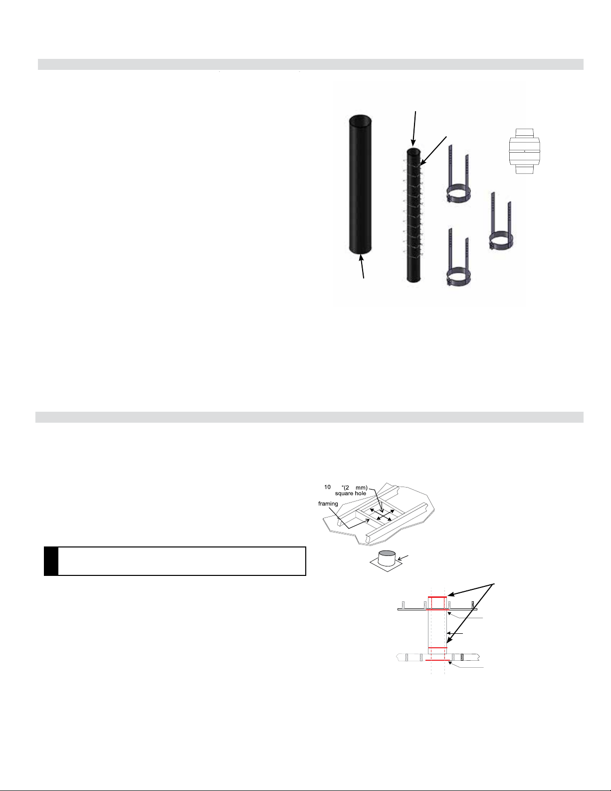
64 | City Series CC40E-11
installation
919-696 08.10.16
1. Stretch out both inner 4" (102 mm) and outer 6 7/8" (175 mm) pipe up to
a maximum of 20 feet.
Note :The inner and outer pipes may be cut if only a short length is required.
2. Install spring spacers around 4" (102 mm) inner pipe as shown.
Slide outer flex pipe over and all the way down the 4" pipe.
3. Apply a bead of Mill Pac around the perimeter of the 4" (102 mm)
inner collar of the flex adapter and slip the 4" (102 mm) inner flex pipe
from the Vertical termination kit over the flex adapter ensuring that the
inner flex pipe overlaps the collar by at least 1-3/8" (35 mm). Fasten with
3 screws.
4. Apply a bead of Mill Pac around the perimeter of the 6-7/8" (175 mm)
outer collar of the flue adapter and slip it over the 6-7/8" (175 mm) outer
flex pipe from the vertical termination kit ensuring that the outer flex pipe
overlaps the collar by at least 1-3/8" (35 mm). Fasten with the 3 screws.
5. Repeat steps to secure the other end of the flex adapter using the flex kit.
6. See Vertical Vent installation instructions for installation of the complete
vent system.
Note: If an offset is necessary in the attic or floor joists it is important to
sup-port the vent pipe every 3 feet (0.91 m) to avoid excessive stress and
sagging of the vent pipe. Wall straps are provided (3 in total) for this
purpose.
All round/plumbers strapping may also be used if further supports are
required.
VERTICAL FLUE EXTENSION KIT (PART # 946-756)
20 foot (6.1 m) Flex pipe Extension
(Used in conjunction with the 946-755 Vertical Flex kit and 948-367/P ex
to ex adaptor).
3 wall straps
ex adaptor
4" (102 mm) inner
pipe 20ft. (6.1 m)
6-7/8" (175 mm)
outer ex pipe
20 ft (6.1 m)
10 spring spacers
1
919-698
919-698
06.12.18
06.12.18
60
-1/4
Ceiling firestop
60
-1/4
Ceiling firestop
Diagram 1
Diagram 1
Diagram 1a
Diagram 1a
Enclosure
Ceiling firestop
Flashing
Termination Cap
Storm Collar
Roof support
Ceiling firestop
Enclosure
Ceiling firestop
Flashing
Termination Cap
Storm Collar
Roof support
Ceiling firestop
Firestop spacer to prevent
debris from falling into the ceiling
restop
CEILING FIRESTOP/FIRESTOP SPACER
( PART # 946-757)
Used in conjunction with the 946-755 Vertical Flex Kit and 946-756 Vertical
Flex Extension Kit/Horizontal Power Vent Kit.
CEILING FIRESTOP/FIRESTOP SPACER
( PART # 946-757)
Used in conjunction with the 946-755 Vertical Flex Kit and the 946-756 Verti-
cal Flex Extension Kit/Horizontal Power Vent Kit.
Firestop spacer to prevent
debris from falling into the ceiling
restop
A ceiling restop/restop spacer must be installed when passing through
each oor or ceiling level. To install the ceiling restop/restop spacer in
a at ceiling or oor joist, cut a 10- ¼ inch square hole, frame it as show
in Diagram 1, and install the ceiling restop. Slide the top attic insulation
spacer onto the top of the attic insulation shield/restop (see Diagram 1a).
Secure with 4 screws/nails. If more than one restop is required, these can
be purchased separately.
NOTE
• The ceiling restop/restop spacer may be cut down to size if the
shield is too high for the application.
NOTE
• The ceiling restop/restop spacer may be cut down to size if the
shield is too high for the application.
A ceiling restop/restop spacer must be installed when passing through
each oor or ceiling level. To install the ceiling restop/restop spacer in
a at ceiling or oor joist, cut a 10- ¼ inch square hole, frame it as show
in Diagram 1, and install the ceiling restop. Slide the top attic insulation
spacer onto the top of the attic insulation shield/restop (see Diagram 1a).
Secure with 4 screws/nails. If more than one restop is required, these can
be purchased separately.
1
1
Vertical Flue Extension Kit (Part #946-756)
Ceiling Firestop / Firestop Spacer (Part #946-757)
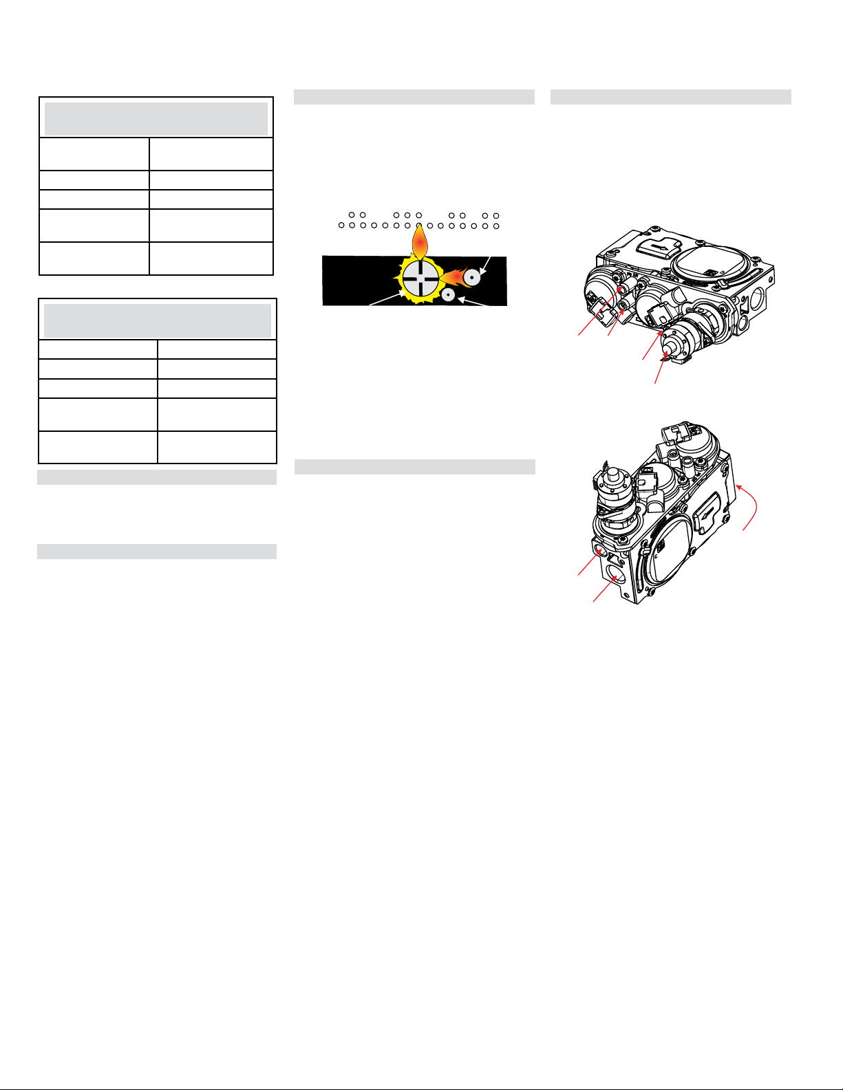
City Series CC40E-11 | 65
installation
Gas Pipe Pressure Testing
The appliance must be isolated from the gas sup-
ply piping system by closing its individual manual
shut-off valve during any pressure testing of the
gas supply piping system at test pressures equal
to or less than 1/2 psig. (3.45 kPa). Disconnect
piping from valve at pressures over 1/2 psig.
The manifold pressure is controlled by a regulator
built into the gas control, and should be checked
at the pressure test point.
Note: To properly check gas pressure, both
inlet and manifold pressures should
be checked using the valve pressure
ports on the valve.
1 Make sure the unit is in the "OFF" position.
2. Loosen the "IN" and/or "OUT" pressure tap(s),
turning counterclockwise with a
1/8" wide flat screwdriver.
3. Attach manometer to "IN" and/or "OUT" pres-
sure tap(s) using a 5/16" ID hose.
4. Turn the unit on with the remote or wall switch
5. The pressure check should be carried out with
the unit burning and the setting should be within
the limits specified on the safety label.
6. When finished reading manometer, turn off
the unit, disconnect the hose and tighten the
screw (clockwise) with a 1/8" flat screwdriver.
Note: Screw should be snug, but do not over
tighten.
High Elevation
This unit is approved for altitude 0 to 4500 ft. (CAN1
2.17-M91).
Gas Line Installation
Since some municipalities have additional local
codes it is always best to consult with your local
authorities and the CAN/CGA B149 installation
code.
For USA installations follow local codes and/or the
current National Fuel Gas Code, ANSI Z223.1.
When using copper or flex connectors use only
approved fittings. Always provide a union so that
gas lines can be easily disconnected for servicing.
Flare nuts for copper lines and flex connectors are
usually considered to meet this requirement.
NOTE: A shutoff / dante valve should be sup-
plied in or near the unit (or as per local codes)
for ease of servicing this appliance.
IMPORTANT: Always check for gas leaks with
a soap and water solution or gas leak detector.
Do not use open flame for leak testing.
CC40LE/CC40RE-11 NG Sys-
tem Data
Min. Supply
Pressure
5" WC (1.25 kpa)
Manifold Pressure 3.8" WC (0.94 kpa)
Orifice Size #42 DMS
Maximum Input 28,500 Btu/h
(8.33 kW)
Minimum Input 15,500 Btu/h
(4.54 KW)
CC40LE/CC40RE-11 LP System
Data
Min. Supply Pressure 11" WC (2.73 kpa)
Manifold Pressure 10.5" WC (2.62 kpa)
Orifice Size #53 DMS
Maximum Input 28,500 Btu/h
(8.35 kW)
Minimum Input 15,500 Btu/h
(4.54 KW)
Note: If you have an incorrect flame
pattern, contact your Regency
®
dealer for further instructions.
Incorrect flame pattern will have small, probably
yellow flames, not coming into proper contact
with the rear burner or flame sensor.
Burner
Flame Sensor
Pilot
Ignitor
Pilot Adjustment
Periodically check the pilot flames. Correct flame
pattern has two strong blue flames: 1 flowing
around the flame sensor and 1 flowing across
the burner (it does not have to be touching the
burner).
885 S.I.T. Valve Description
1) 6 Stage flame adjustment
2) Pilot adjustment
3) Outlet Pressure Tap
4) Inlet Pressure Tap
5) Pilot Outlet
6) Main Gas Outlet
7) Main Gas Inlet
1
2
3
4
6
5
7
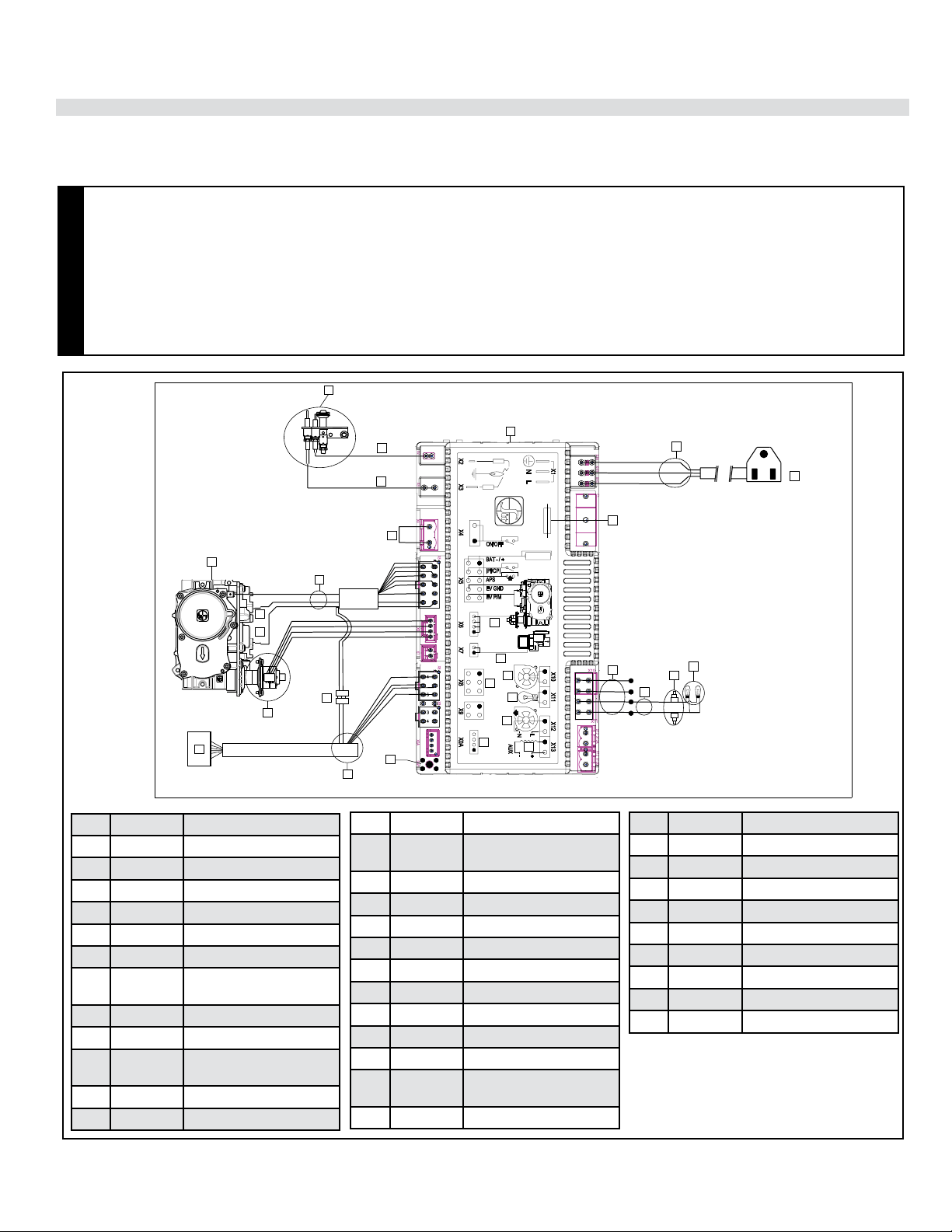
66 | City Series CC40E-11
installation
Wiring Diagrams
1
2
3
4
5
7
9
11
10
12
14
15
17
18
19
20
21
22
23
27
28
24
26
25
6
13
16
29
8
CAUTION
• Label all wires prior to disconnection when servicing controls. Wiring errors can cause improper and dangerous operation.
• Ensure that the wires do not touch any hot surfaces and are away from sharp edges.
• The IFC (Intermittent Fireplace Control) serves as the power source for this unit when plugged into a 120-volt receptacle.
The 4 x AA batteries in the battery holder are recommended as a backup in case 120-volt power is lost within the home.
• If replacing any of the wiring or wiring harnesses supplied with the appliance, you must purchase the same wiring or wiring
harnesses that came with the appliance. Do not substitute wiring.
• This appliance is equipped with a three-prong (grounding) plug for your protection against shock hazard and should be
plugged directly into a properly grounded three-prong receptacle. Do not cut or remove the grounding prong from this plug.
Item Part # Description
1 911-276 Pilot Assembly NG
911-277 Pilot Assembly LP
W840470 Pilot Gasket (not shown)
2 911-038 Spark Electrode
3 911-037 Flame Sensor Electrode
4 911-266/P PFII IFC Board
5 911-192 Power Harness w/Aux
Connector
6 N/A Main Line
7 911-182 Fuse
8 911-072 Halogen bulb
G9/120V/25W
9 911-208 Oven Lamp w/Wires
10 911-209 Wire 2 pos. IFC Fan
Item Part # Description
11 911-177 Wire 4 pos. IFC Fan &
Light
12 N/A Load
13 N/A Diagnostic Interface
14 N/A Combustion Blower
15 N/A Lamp
16 N/A User Interface
17 N/A Comfort Fan
18 N/A Split Flow
19 N/A Motor
20 N/A Switch
21 911-181 Battery Holder WIre Har-
ness
22 911-337/P Battery Holder
No electrical power supply is required for the gas control to operate. 120 Volt
AC power is needed for the lights. A receptacle box, receptacle and cover are
provided and located on the left hand side of the unit, under the outer base panel.
Electrical power must be brought to the appliance
by a licensed electrician.
Item Part # Description
23 911-190 Flame Modulator-NG
911-191 Flame Modulator LP
24 N/A Battery Connection
25 N/A Adjustment Screw
26 911-242 Gas Pressure Ports
27 911-173 Valve Wire Harness
28 911-188 Valve NG
28 911-189 Valve LP
29 911-193 Connector w/Jumper

City Series CC40E-11 | 67
installation
Inner Glass Panel (Firebox Glass) Installation / Removal
1. Remove outer safety glass panels if previously installed–see instructions
in this manual.
2. CC40LE/CC40RE Single sided & CC40LE/CC40RE 3 Sided Units—Re-
move outer panels installed in units - see panel removal section in this manual.
Single sided units–proceed to Step 5.
3. Ensure all 4 clamps on each side are open to allow clearance for the glass.
Lift up side panel using supplied vacuum clamp and tilt inward and upward
positioning into a top channel and lowering gently into the lower glass chan-
nel–slide the side glass panel firmly towards the back wall until the springs
at the back wall are compressed.
4. With the springs compressed, close the 2 clamps at the bottom and 2 clamps
at the top, by turning inward, to secure the glass in position. For the 3 sided
unit, repeat on the opposite side.
Top clamps in
open position
Bottom side clamps in
open position
CC40LE/CC40RE shown
CC40LE/CC40RE shown
Bottom
channel
Top clamps in
closed position
Bottom clamps in
closed position
Push side glass
panel firmly
to back wall
until springs are
compressed—
then close
clamps.
Important:
Prior to installing the inner glass, ensure that there is no media present in
the bottom channel as this can cause damage to the glass. Remove any
media from bottom channel prior to installing the glass.
WARNING: GLASS HANDLING
We recommend using the glass vacuum holders supplied by the manufac-
turer. Lower the glass to rest in a safe place, this is to prevent damage to the
glass edges. Extra care must be taken when removing/installing the glass.
Breakage or damage to the edge of the glass which occurs as a result of
careless handling will not be covered under warranty.
• We recommend handling the glass with supplied vacuum
clamps
• When removing glass–prepare a soft, scratch resistant
surface to place the glass
• Never clean or remove hot glass
Note: The suction cups may leave a round film on the glass
when used. Ensure that the glass is cleaned using a fireplace
glass cleaner prior to operating the appliance.
Note: glass panels must be installed to operate fireplace
To watch the firebox installation video click here http://bit.ly/2qfQwST

68 | City Series CC40E-11
installation
Note: Ensure that the front glass is centered and evenly spaced with side glass
(3 sided unit) - open to release glass clamps to remove from surface of glass.
CC40LE shown
Handle front panel with supplied vacuum clamps
tooltip
Open clamps
prior to plac-
ing front glass
panel
5. Ensure all 7 front clamps are in the open position to allow clearance for
the glass.
6. Lift up the front panel using the supplied vacuum clamps and position into
the lower front channel–ensure the front panel is accurately centered—with
the front panel in position—secure in place by closing the 3 lower clamps
and 4 upper clamps.
Open clamps to
release pressure on
the springs
Press glass vacuum clamps (part # 948-078/pair) in open position firmly onto
surface of glass. Bring handles together to close.
Open
Closed
7. Return to the side panel(s), and release the upper and lower clamps. The
springs will release and push the glass side panel forward slightly—this will
create a seal between the front and side panels. When the junction between
the front and side glass panels is sealed, close the clamps to secure the
side panel(s) in place.
8. To remove the glass panels—always remove the side panel(s) (for 3 sided
units) before removing the front panel.
9. Reverse steps to remove glass.
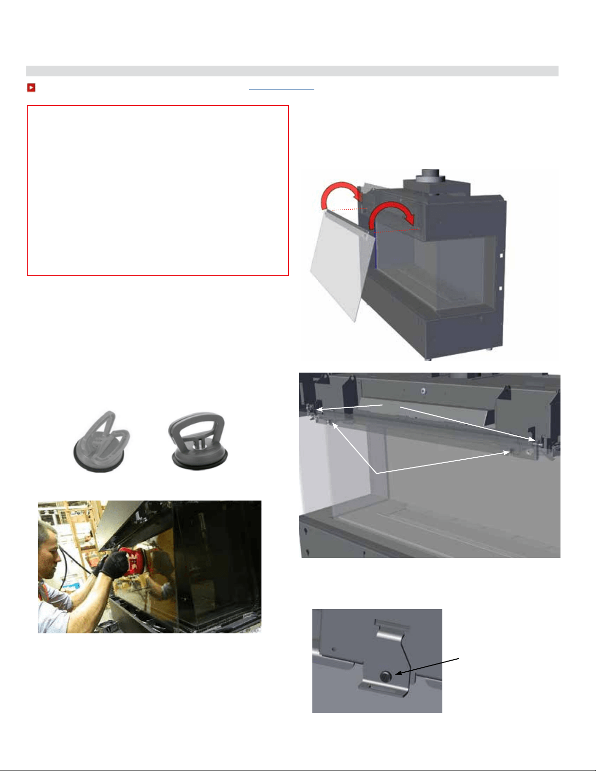
City Series CC40E-11 | 69
installation
To watch the safety barrier glass installation video click here http://bit.ly/2ryq0c0
Outer Safety Glass Panel (Barrier Glass) Installation / Removal
Outer glass safety panels to be installed during the initial installation after the
unit is in the final position.
Note: The outer safety panels come with plastic corners to protect these against
damage. These should be kept in place until such time the outer safety panels
are installed. Ensure these are removed prior to operating the appliance. Keep
the plastic corners in a safe place if ever removing the outer panels for servicing.
1. Carefully remove glass safety panels from packaging.
3. Tilt the top of the glass panel inward and lift up and underneath
the upper front panel of the outside frame. Hook the glass panel
onto the pins and also onto the two angle adjustment brackets lo-
cated on the frame in two locations as shown in the diagram below.
Note: The front frame upper panel is shown as transparent to better
illustrate the install (this area is not visible when installing glass).
Press glass vacuum clamp (part # 948-078/pair) in open position firmly onto
surface of glass. Bring handles together to close.
Open
Closed
NOTE: Inner glass panel shown in image - depicting proper handling
of glass.
WARNING: GLASS HANDLING
We recommend using the glass vacuum holders supplied by the manufac-
turer. Lower the glass to rest in a safe place, this is to prevent damage to the
glass edges. Extra care must be taken when removing/installing the glass.
Breakage or damage to the edge of the glass which occurs as a result of
careless handling will not be covered under warranty.
• We recommend handling the glass with supplied vacuum
clamps
• When removing glass–prepare a soft, scratch resistant
surface to place the glass
• Never clean or remove hot glass
Note: The suction cups may leave a round film on the glass
when used. Ensure that the glass is cleaned using a fireplace
glass cleaner prior to operating the appliance.
Note: If the outer safety glass panels do not sit at 90º and angle too far
inward or outward, remove the glass panel and adjust the screw of
the panel angle bracket. Turn the panel angle bracket screw in 1/4
increments—reinstall panel to check.
Angle adjustment brackets
Pins on body of unit
Panel angle bracket—to
adjust, turn screw:
Clockwise = bring panel in
Counter clockwise= bring
panel out
2. Using the supplied vacuum clamps, lift the large front glass panel and
position it front and centre by manoeuvering up and underneath the front
of the unit frame.
Note: safety glass panels must be installed to operate fireplace
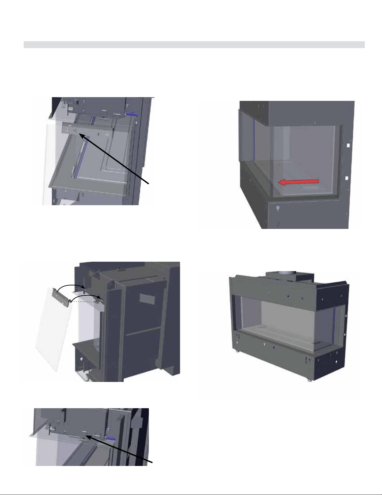
70 | City Series CC40E-11
installation
Outer Safety Glass Panel (Barrier Glass) Installation / Removal
Note: safety glass panels must be installed to operate fireplace.
Note: If the outer safety glass side panels angle too far inward or outward,
remove the side glass panel and adjust on the panel angle bracket,
see details on previous page.
5. Lift up the side panel with the supplied glass clamps (see procedure on
previous page). Tilt the side of the glass panel inward and lift up and under-
neath the upper side panel and hook the 2 outer hooks on to the pins, there
is also a panel angle adjustment bracket for the third hook.
Note: The side frame upper panel is shown as transparent to better
illustrate the install (this area is not visible when installing glass).
4. For 3 sided and corner units only:
With front panel installed, proceed to install the side panel(s).
Identify the left and right side panels before installing. Facing the front of
the unit, the right panel will show an arrow pointing to the front of the unit
as shown in the diagram below.
Note: The side frame upper panel was made transparent to better
illustrate the install (this area is not visible when installing glass).
Note: After the side panel has been adjusted so it is installed at 90º to the
unit and not flaring in or out, check to ensure there is no gap between
the front and side panel. If there is a gap as shown below, slide the side
panel to adjust the position and close the gap.
Direction arrow on side
panel bracket, should
point toward front of
unit
6. Repeat Steps 4 and 5 to install the opposite side panel.
7. Reverse Steps to remove all panels.
Note: When removing panels, we recommend using the supplied glass clamps.
Panel angle bracket
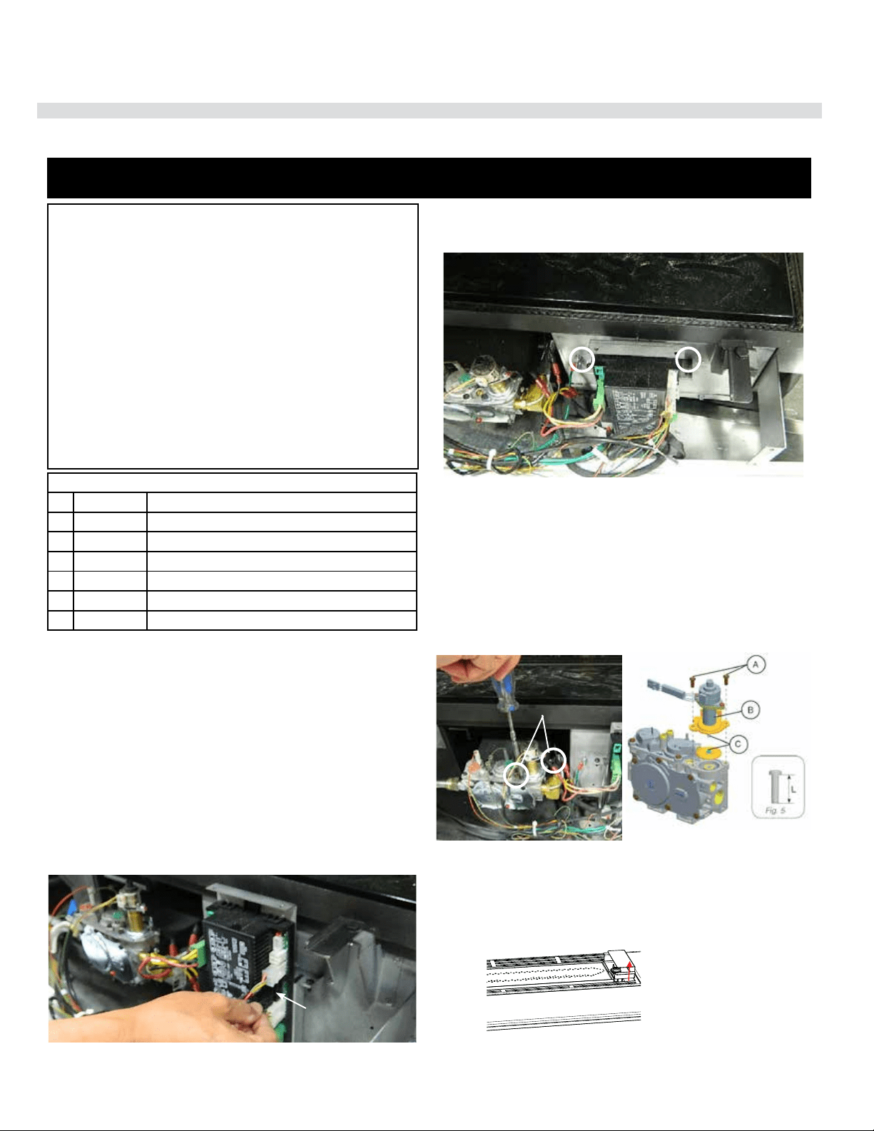
City Series CC40E-11 | 71
installation
LP Conversion Instructions
920-040
02.13.19
1
CITY SERIES
CONVERSION FROM NG TO LP
CV40E/ CB40E/CC40E-11 using SIT 885 NOVA Gas Valve
Caution: The gas supply shall be shut off prior to disconnecting the
electrical power, before proceeding with the conversion.
Always let the appliance cool to room temperature before servicing.
1. Remove the outer panels and safety glass — see manual.
2. Remove inner ceramic glass — see manual.
3. Remove inner panels — see manual.
4. Remove all media installed on burner (glass, logs or stones, etc).
5. Disconnect the Cable coming from the Pressure Regulator Motor.
6. If unable to access this Cable - undo 2 screws securing the IFC Board
and slide out of unit to access cable.
WARNING
This conversion kit shall be installed by a qualified
service agency in accordance with the manufac-
turer’s instructions and all applicable codes and
requirements of the authority having jurisdiction.
If these instructions is not followed exactly, a fire,
explosion or production of carbon monoxide may
result causing property damage, personal injury
or loss of life. The qualified service agency is re-
sponsible for the proper installation of this kit. The
installation is not proper and complete until the
operation of the converted appliance is checked as
specified in the manufacturer’s instructions sup-
plied with the kit.
THIS CONVERSION MUST BE DONE BY A QUALIFIED GAS FITTER
IF IN DOUBT DO NOT DO THIS CONVERSION!
Cable from motor
Conversion Kit 657-977 includes:
1 911-191 Stepper Motor LP for 885 SIT
1 904-947 Orifice #53
1 910-037 Pilot Orifice #30
1 918-590 Decal - Conversion to LP
1 908-528 Label Propane
1 904-529 5/32" long Allen Key
1 920-040 Instruction Sheet
7. Remove and discard 2 Pressure regulator screws (A)using a (T20 or slot
screwdriver,) Pressure Regulator (B) and Spring and Diaphragm (C)
(see below).
8. Ensure the rubber gasket, which is prefitted as part of the Assembly,
is properly positioned. Install the new Pressure Regulator using the 2x
M4 x .7 screws supplied. Tighten the screws to 25lb-in. In the event that
the screw threads are cross threaded or stripped, replace the valve as-
sembly.
Install the enclosed propane identification label to the valve body where it
can be easily seen.
Pressure
regulator
screws
9. Re-attach the Pressure Regulator wire (disconnected in Step 6), and re-
situate the IFC, secure the screws that fasten the IFC Mounting Brackets.
10. Remove pilot hood by lifting up and off.
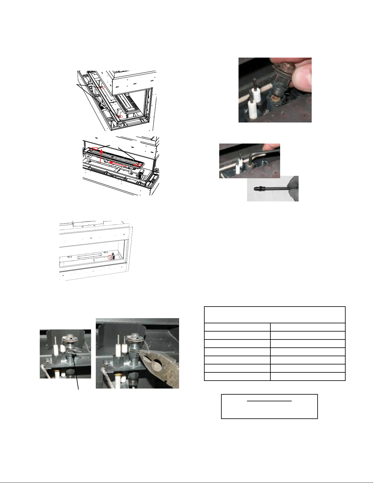
72 | City Series CC40E-11
installation
920-040 02.13.19
2
CITY SERIES
15. Reinstall pilot cap and pilot retainer clip.
16. Prior to installing burner—adjust aerations settings - to 1/4" for
LP.(CB40E/CC40E/CV40E/CB40EPV/CV40EPV/CC40EPV) or 3/8"
(CB40E-1/CC40E-1/CV40E-1) Reinstall burner (see Step 13).
17. Ensure the pilot light is in the correct orientation to the Burner. Recon-
nect the gas and electrical supply to the appliance. Start the appliance.
(see section on Lighting Instructions) Ensure that pilot and burner igni-
tion is completed without delay. Check both your inlet and outlet pres-
sures at full load. With a soapy solution, leak test the entire system.
Verify both the correct flame and pilot appearance.
18. See Gas Pipe Pressure Testing in manual.
13. Remove pilot retainer clip with pliers and pull off the pilot cap to expose
the pilot orifice.
14. Unscrew the pilot orifice with the allen key; then replace with the LPG
pilot orifice and the pilot cap, provided in the kit.
Installer Notice:
These instructions must be left
with the appliance
.
Pilot retainer clip
12. Remove burner orifice with a 3/8" wrench. Use another wrench to hold
on to the elbow behind the orifice. Discard orifice. Reinstall new burner
orifice LPG stamped #53 and tighten.
Burner Orice
Location
CV40E shown
11. Loosen 4 screws in locations shown below (2 at front and 2 at rear)—slide
burner to the left away from the orifice and lift out.
front
screw locations
back screw locations
City Series
LP SYSTEM DATA
Min. Supply Pressure 11" WC (2.73kpa)
Manifold Pressure - High 10.5" WC (2.62 kpa)
Manifold Pressure - Low 2.9" WC (0.72 kpa)
Orice Size #53 DMS
Maximum Input 28,500 Btu/h (8.35 kW)
Minimum Input 15,500 Btu/h (4.54 KW)
Altitude 0-4500 ft (0-1372m)
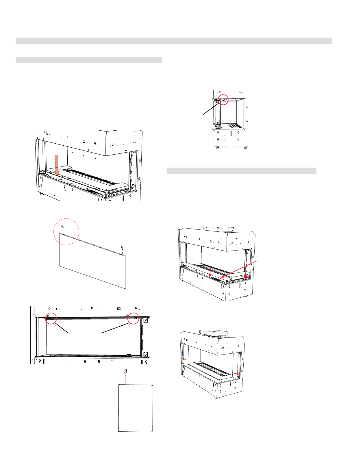
City Series CC40E-11 | 73
installation
919-742
11.07.16
CC40RE/CC40LE INNER PANELS
1. Install inner lower base panel.
2. Install panel clips into the slots at the top of the back panel as shown.
4. Install panel clip into the slots at the top of the
side panel as shown.
3. Manoeuvre in back panel to the back wall of the unit—secure in place
with 2 panel clips and 2 screws.
5. Manoeuvre in side panel to the side wall of the unit—secure in place
with 1 panel clips and 1 screws.
CC40RE/CC40LE OUTER PANELS
Outer side panel install
Outer base panel install
Note: Install inner safety glass prior to installation of outer panels-see
instructions in manual
1. Attach Regency logo to the right hand side of outer front panel. The
magnets will be positioned under the outer front base panel to secure
the logo. The logo should be about 3 inches from the right hand corner
of the outer base. Install outer front and side base panel.
2. Install side panels - the side panels are secured in place by existing
magnets in the unit.
The CC40RE/CC40LE can be equipped with optional steel inner panels.
There are 4 outer panels and 3 inner panels.
NOTE: CC40RE shown in diagrams—CC40LE panels install in the same
order. Installed panels for the CC40LE will appear as mirror images of
diagrams shown below.
Turn off unit and allow to cool to room temperature. Remove the safety
glass and firebox glass — see manual for instructions.
3. Install outer safety glass.
4. Reverse steps to remove panels.
6. Reverse steps to remove panels.
tooltip
Panel Clips
Panel Clip
Location of
Regency Logo
tooltip
1
CITY SERIES
Inner Panels
Outer Panels
Painted Panel Installation
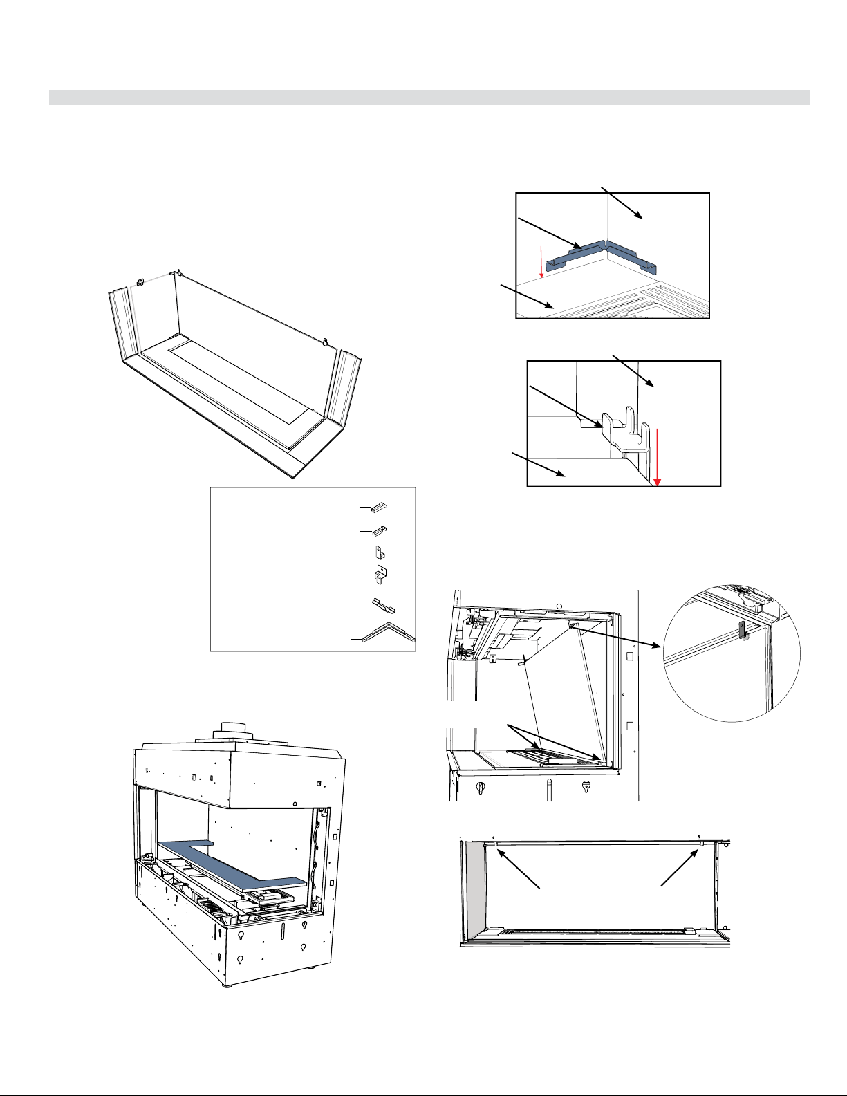
74 | City Series CC40E-11
installation
Glass Panel Installation
919-744a
01.10.17
CC40LE/CC40RE GLASS PANEL INSTALLATION
1. Tu rn off unit and allow to cool to room temperature. Remove the outer safety
glass and inner ceramic fi rebox glass panels and any media installed — see
manual for instructions. CC40RE shown in diagrams.
NOTE: CC40RE shown in diagrams—CC40LE panels install in the same or-
der. Installed panels for the CC40LE will appear as mirror images of diagrams
shown below.
2. Identify panels and order of installation.
bottom corner
brackets
5. Carefully manoeuvre the back glass panel (2) to the back wall of the fi rebox.
Center the glass panel and position bottom of panel into brackets installed in
step 4. Place the 2 top back brackets on the top edge of the glass and secure
to the unit with one screw on each side once back glass panel is in position.
4. Slide the supplied bottom corner bracket behind the small panel (1) and the
back and side walls, in the orientation shown below.
3. Install the inner base panel (1) around burner as shown below.
back wall of unit
bottom
corner bracket
656-206
base panel
Top back
bracket
orientation
656-202
back wall of unit
bottom
back bracket
656-218
base panel
Y5PQ$PSOFS#SBDLFU$$3
Y5PQ#BDL#SBDLFU
Y5PQ$PSOFS#SBDLFU$$-
Y5PQ4JEF#SBDLFU
Y#PUUPN#BDL#SBDLFU
Y#PUUPN$PSOFS#SBDLFU
Glass Panel Parts Layout
Top back
bracket location
656-202
1
CITY SERIES
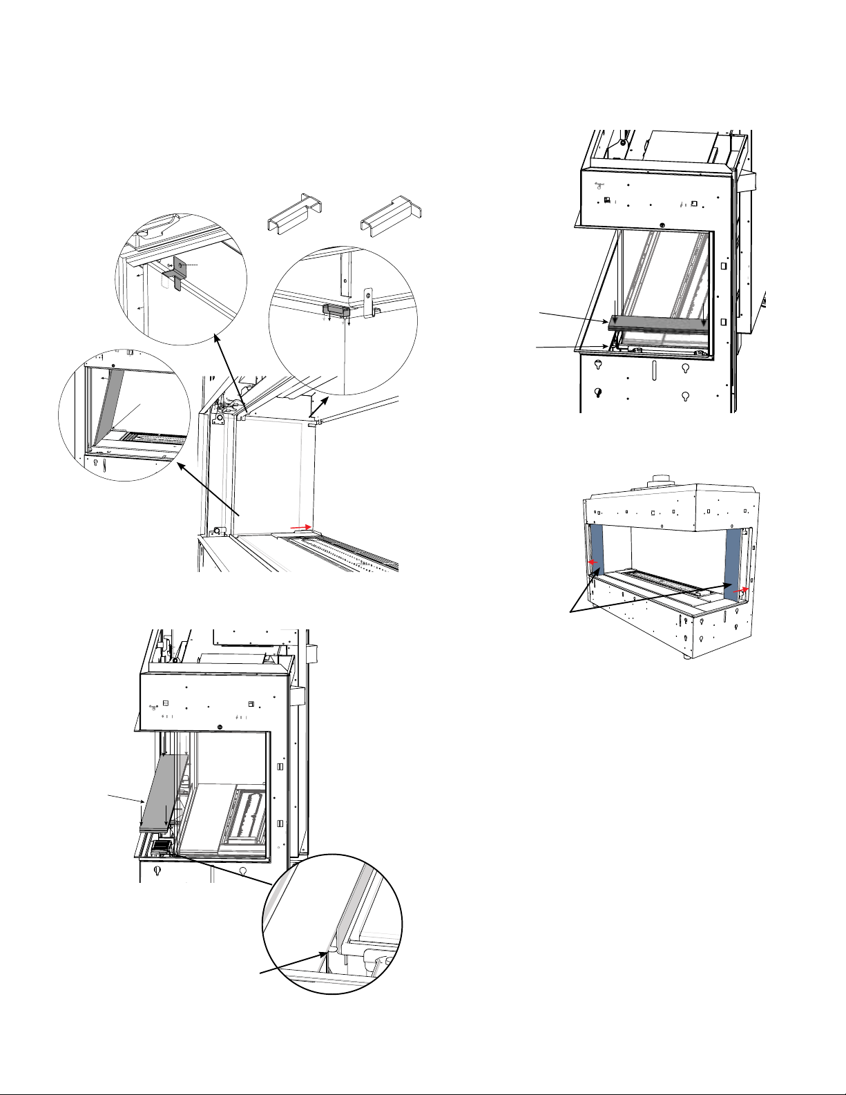
City Series CC40E-11 | 75
installation
919-744a 01.10.17
Outer side panels
(6, 7)
11. Install outer safety barrier glass (3 pieces). See manual for instructions.
12. Reverse Step 1 to reassemble unit.
13. Reverse steps to remove panels.
a
nel 6
P
anel 7
8. Install front outer base panel (4)
Note: there are tabs on panel 4 that should face inward.
Tab
Panel 6
6. Carefully manoeuver the Side Glass Panel (3) into the side of the fi re-
box. Position the bottom of the panel into the Bottom Corner Bracket
and secure the top using the Top Side Bracket as shown. Once in
position, secure the Top Side Bracket to the side wall with one screw.
Slide the appropriate Top Corner Bracket over the corner between the
Side and Back glass panels.
9. Install outer side base panel (5) — panel 5 rests on the tab of panel 4.
10. Install outer side panels (6, 7) — both panels are held in position with
magnets.
7. Reinstall inner ceramic fi rebox glass panels (see manual for instructions).
Bottom Side Bracket
Use with CC40L
Use with CC40R
Panel 4
Tab on Panel 4
Panel 5
656-205
656-203
656-203
656-202
656-204
2
CITY SERIES
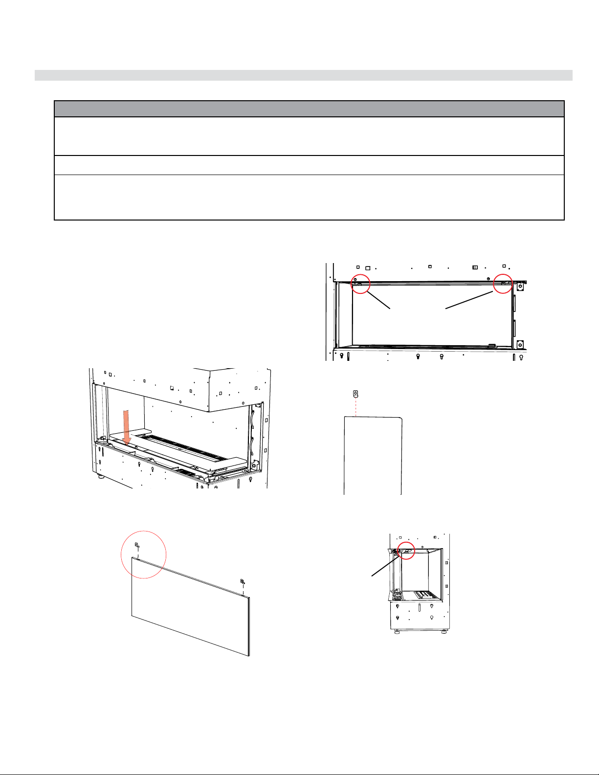
76 | City Series CC40E-11
maintenance
Enamel Panel Installation
919-743
11.25.16
CC40RE/CC40LE ENAMEL PANEL INSTALLATION
Black Enamel Panels — Handling Instructions
• Black Enamel panels must be inspected for scratches and dimples prior to installation.
All claims to be recorded at this time.
Claims for damage after installation will not receive consideration.
• Black Enamel panels will discolor a little during normal operation. This is normal and should not be considered a defect.
*
All hand and finger marks MUST be cleaned off with a soft cloth. Use an ammonia based cleaner (ie. glass cleaner) to remove any fingerprints before
applying heat to the unit.
Failure to do this will result in burn stain on panels which you will be unable to remove and will not be protected by product warranty.
1. Install inner lower base panel.
2. Install panel clips into the slots at the top of the back panel as shown.
4. Install panel clip into the slots at the top of the side panel as shown.
3. Manoeuvre in back panel to the back wall of the unit—secure in place
with 2 panel clips and 2 screws.
5. Manoeuvre in side panel to the side wall of the unit—secure in place
with 1 panel clip and 1 screw.
The CC40RE/CC40LE can be equipped with optional enamel panels.
There are 4 outer panels and 3 inner panels.
NOTE: CC40RE shown in diagrams—CC40LE panels install in the same
order. Installed panels for the CC40LE will appear as mirror images of
diagrams shown below.
Turn off unit and allow to cool to room temperature. Remove the safety
glass and firebox glass — see manual for instructions
6. Reverse steps to remove panels.
Panel Clips
Panel Clip
tooltip
CC40RE/CC40LE INNER PANELS
1
CITY LINE
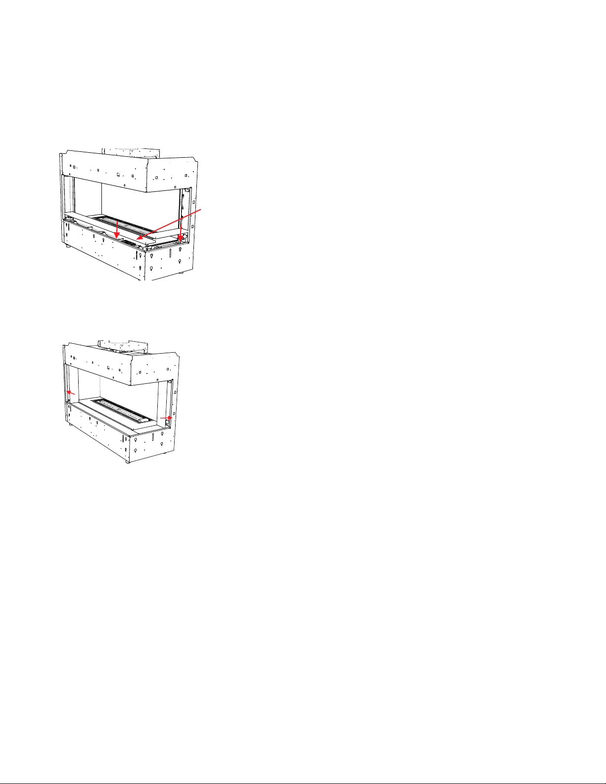
City Series CC40E-11 | 77
maintenance
919-743 11.25.16
CC40RE/CC40LE OUTER PANELS
Outer side panel install
Outer base panel install
Note: Install inner safety glass prior to installation of outer panels-see
instructions in manual
1. Attach Regency logo to the right hand side of outer front panel. The
magnets will be positioned under the outer front base panel to secure
the logo. The logo should be about 3 inches from the right hand corner
of the outer base. Install outer front and side base panel.
2. Install side panels - the side panels are secured in place by existing
magnets in the unit.
3. Install outer safety glass.
4. Reverse steps to remove panels.
Location of
Regency Logo
2
CITY LINE
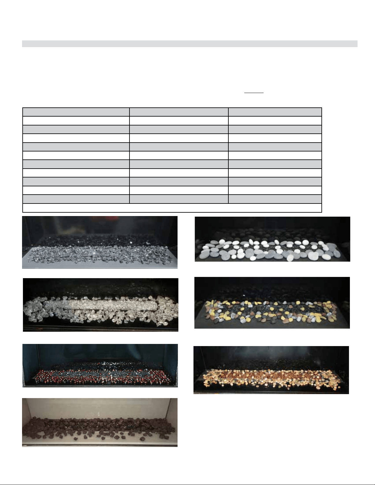
78 | City Series CC40E-11
installation
Burner and Firebox Media Options
Spread the media evenly over the burner. Ensure the glass/stones do not overlap excessively as this will affect the flame pattern.
IMPORTANT NOTE:
Only the supplied approved media are to be used with these fireplaces. Use of any other type of glass or stones can alter the unit's performance. Any damage
caused by the use of any unapproved glass or stones will not be covered under warranty.
When using Ceramic Spa/Volcanic Stones ensure required glass crystals/beads are used as a base. DO NOT overstack Ceramic Spa Stones or Volcanic
Stones on burner or in the pilot area. Media must be installed on and around burner only in amounts noted below.
CC40LE/CC40RE Approved Media*
Where Used Quantity
Fireglass (starfire, copper or black) On burner 1.5 lbs
Glowing embers/sea wool (supplied with unit) On burner 1 bag
Natural Stones Around burner 1 box = 15lbs
Ivory Natural Stones Around burner 1 box = 15lbs
3/4" Crushed black glass Around burner 3.5lbs
Crushed Iceburg chips Around burner 3.5lbs
Firebeads Around burner 3.5lbs
Spa stones Around burner 2 boxes
Lava Embers Around burner 6 packages
Stone River Pebbles Around burner 2 bags
* Media not supplied with unit - must be purchased separately.
3/4" Crushed black glass + Black Fireglass
Spa Stones + Fireglass
Stone River Pebbles + Fireglass
Natural / Ivory Stones + Fireglass
Starfire Fireglass + Iceburg chips
Fireglass + Firebeads
Lava Embers + Black Fireglass
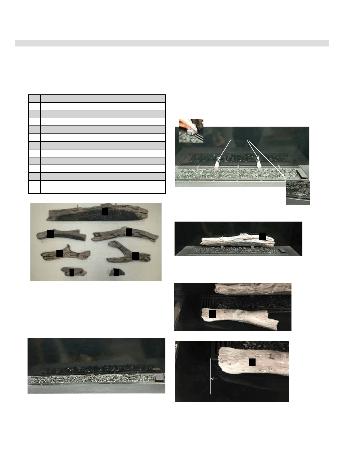
City Series CC40E-11 | 79
installation
919-651b
10.03.18
Read the instructions below carefully and refer to the images. If the logs are broken do not use the unit until they are replaced. Broken
logs can interfere with pilot operation.
Improper positioning of the logs may create carbon build-up and can alter the unit's performance which is not covered under warranty.
*Dark brown paint is included if touch ups are required.
1 Rear Log
2 Left Log
3 Right Log
4 Left Cross Log
5 Right Cross Log
6Front Left Log Piece
7Front Right Log Piece
Log Brackets (3)
Lava rock (purchased separately from log set)
1 lb Black Fireglass (purchased separately from log set)
Glowing wool (supplied with unit)
3/4" Crushed black glass or iceburg chips
(purchased separately from log set)
1
3
5
2
4
6 7
1. S hut off gas and electrical supply, allow unit to cool to room temperature.
2. Remove safety glass and fi rebox glass (see manual).
3. Carefully remove the logs from the packaging and unwrap them.
The logs are fragile, handle with care—never force into position.
4. Install Black Fireglass (1.5lb) and glowing wool on the burner as
shown below.
Log Guides - location of log guides,
2 rear - 1 front
5. Clip on the log guides - position the rear guides by centering over the
second and fourth vertical lines at the back of the burner. The front
log guide clips on to the front edge of the burner on the right side as
shown below.
Log 1 in position
Log 2 in position
Burner covered with Fireglass and glowing wool
1
Log guides
2
6. Centre Log 1 and rest on installed rear log guides—with pins facing up.
7. Position Log 2 on the burner— the leftmost edge should be 3/4 inches
away from the edge of the burner. The other end of the log on a slight
diagonal to the front of the fi rebox as shown.
2
3/4" away from the
edge of the burner
1
CITY LINE
CITY LINE - LOG INSTALLATION
Optional Driftwood Log Set Installation
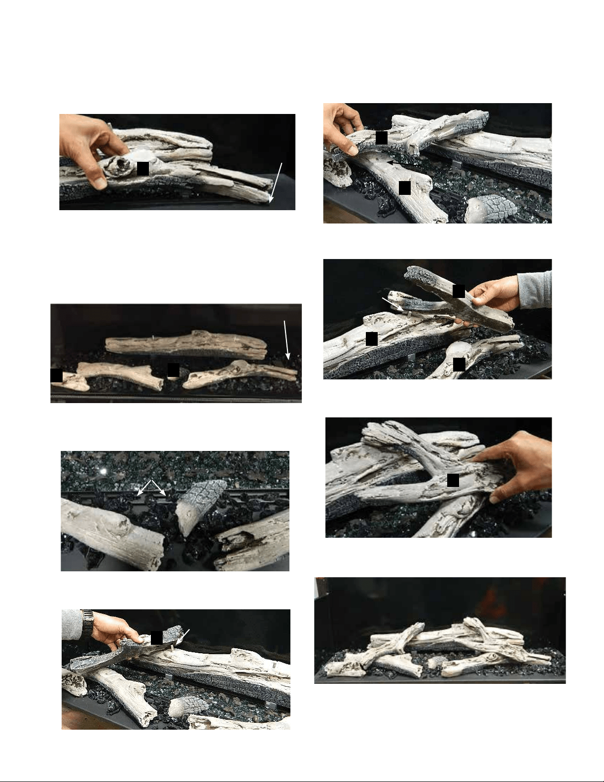
80 | City Series CC40E-11
installation
919-651b 10.03.18
Log 3 placement
Completed Install
3
4
2
5
5
3
1
8. Place the split end of Log 3 to the right front corner of the burner—angle
the log so that the other end is sitting approximately 1/2" (13mm) from
the edge of the burner tray.
7
6
4
9. Place Log 6 and Log 7 on the burner locations shown below.
10. Before placing the next log—spread the optional media evenly
throughout the burner tray as shown.
NOTE: Ensure the installed optional media doesn't completely block the
air fl ow—ensure more than 50% of the airfl ow is open (shown with 3/4"
crushed black glass).
11. Place Log 4—identify the pin locator and match with the left side
pin on Log 1.
Rest the other end of Log 4 on the indent in Log 2 as shown below.
12. Place Log 5—identify the pin locator and match with the right side
pin on Log 1.
Rest the other end of Log 5 on the indent in Log 3 as shown below.
Add lava rock sparsely around the perimeter of the burner.
Log to corner of
burner
Indent Log 2
3/4" crushed
black glass
Do not completely
block air fl ow
Pin in Log 1
Pin in Log 1
2
CITY LINE
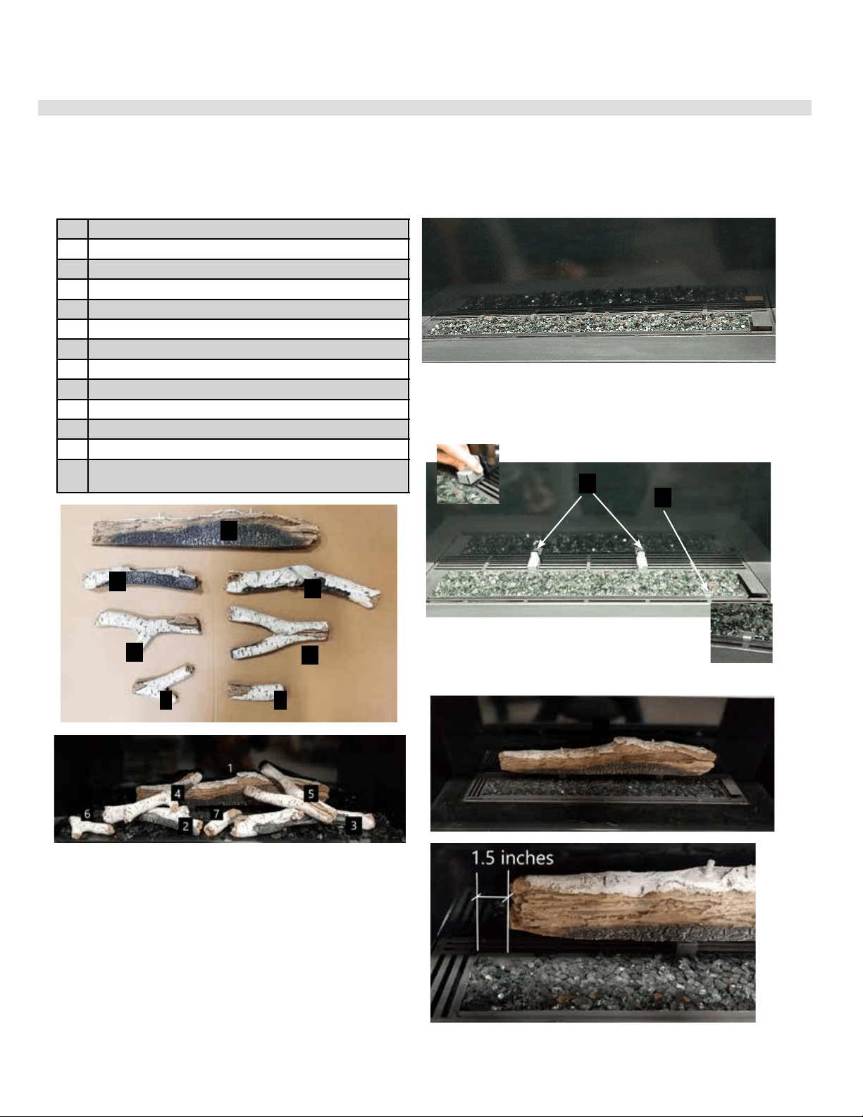
City Series CC40E-11 | 81
installation
Optional Birchwood Log Set Installation
920-074
02.28.19
Read the instructions below carefully and refer to the images. If the logs are broken do not use the unit until they are replaced. Broken
logs can interfere with pilot operation.
Improper positioning of the logs may create carbon build-up and can alter the unit's performance which is not covered under warranty.
*Dark brown paint is included if touch ups are required.
1 Rear Log
2 Left Log
3 Right Log
4 Left Cross Log
5 Right Cross Log
6 Front Left Log Piece
7 Front Right Log Piece
8 Log Brackets (2) Part # 656-047
9 Log Brackets (1) Part # 476-103/F
Lava rock (purchased separately from log set)
1.5 lb Black Fireglass (purchased separately from log set)
Glowing wool (supplied with unit) Part # 946-634
3/4" Crushed black glass or iceburg chips
(purchased separately from log set)
1
3
5
2
4
6 7
1. S hut off gas and electrical supply, allow unit to cool to room temperature.
2. Remove safety glass and firebox glass (see manual).
3. Carefully remove the logs from the packaging and unwrap them.
The logs are fragile, handle with care—never force into position.
4. Install Black Fireglass (1.5lb) and glowing wool on the burner as
shown below.
Log Guides - location of log guides,
2 rear - 1 front
5. Clip on the log guides - position the rear guides by centering over the
second and fourth vertical lines at the back of the burner. The front
log guide clips on to the front edge of the burner on the right side as
shown below.
Log 1 in position
Burner covered with Fireglass and glowing wool
1
6. Centre Log 1 and rest on installed rear log guides—with pins facing up.
8
9
1
CITY LINE
OPTIONAL BIRCHWOOD LOG SET INSTALLATION
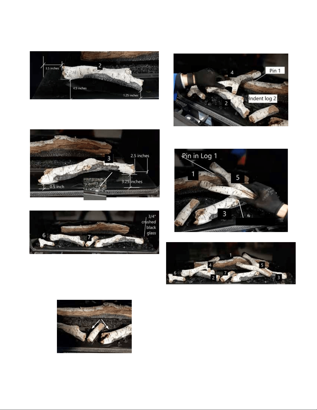
82 | City Series CC40E-11
installation
920-074 02.28.19
Log 2 in position
Completed Install
6. Place Log 1 on the top of the installed rear log guides. Follow the
measurements as shown below.
7. Position Log 2 as shown and follow the measurements.
8. Place Log 3 to the right front corner of the burner. Follow the measure-
ments as shown. Make the edge of the log sit on top of the log guide.
11. Place Log 4—identify the pin locator and match with the left side
pin on Log 1. Rest the Log 4 on the indent in Log 2 as shown below.
12. Place Log 5—identify the pin locator and match with the right side
pin on Log 1. Rest the Log 5 on the indent in Log 3 as shown below.
10. Before placing the next log—spread the optional media evenly
throughout the burner tray as shown.
NOTE: Ensure the installed optional media doesn't completely block the
air flow—ensure more than 50% of the airflow is open (shown with 3/4"
crushed black glass).
9. Place Log 6 and Log 7 on the burner locations shown below.
Do not completely
block air flow
log guide
Log 3 Indent
2
CITY LINE
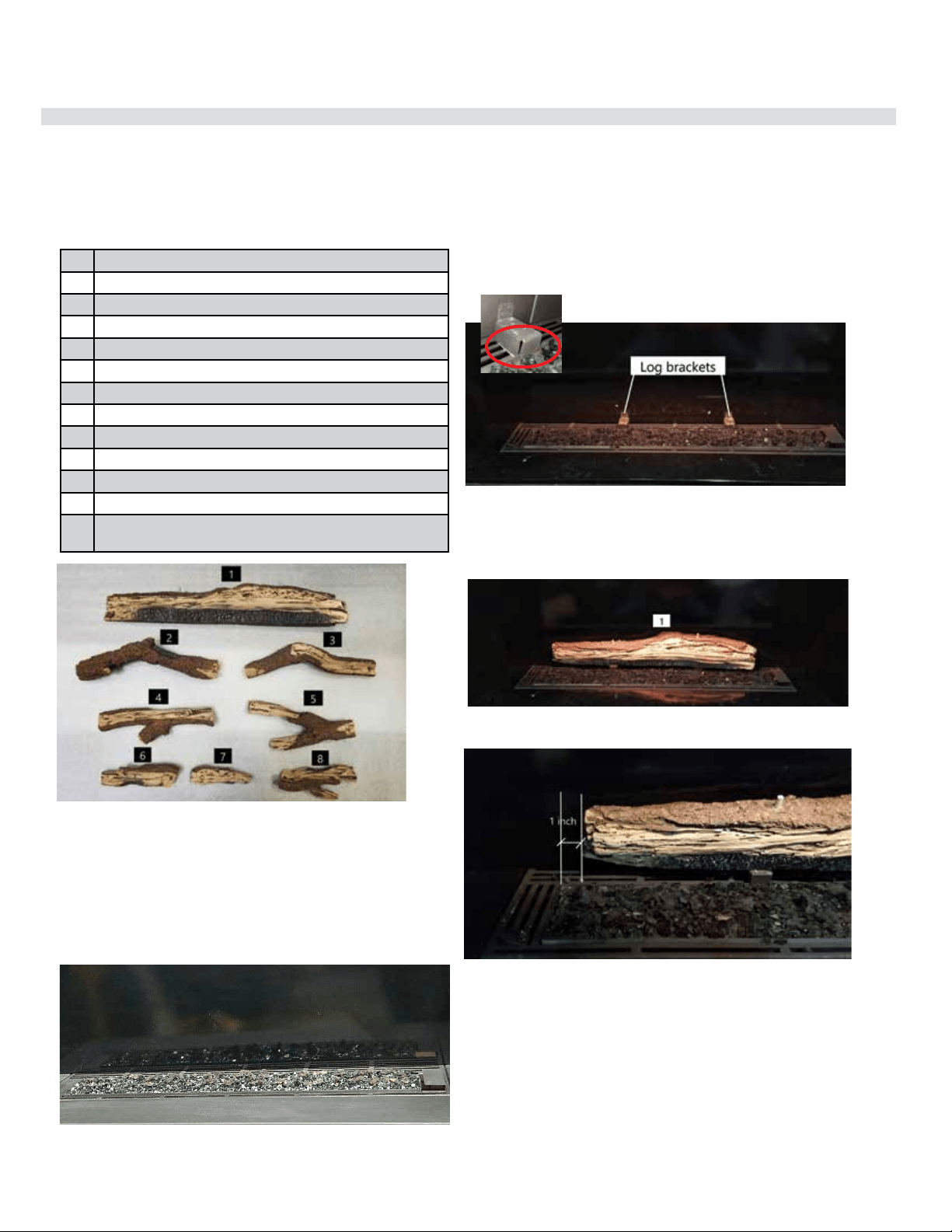
City Series CC40E-11 | 83
installation
Optional Splitwood Log Set Installation
920-086
08.26.19
Read the instructions below carefully and refer to the images. If the logs are broken do not use the unit until they are replaced. Broken
logs can interfere with pilot operation.
Improper positioning of the logs may create carbon build-up and can alter the unit's performance which is not covered under warranty.
*Dark brown paint is included if touch ups are required.
1 Rear Log
2 Left Log
3 Right Log
4 Left Cross Log
5 Right Cross Log
6Front Left Log Piece
7Front Middle Log Piece
8Front Right Log Piece
Log Brackets (2)
Lava rock (purchased separately from log set)
1.5 lb Black Fireglass (purchased separately from log set)
Glowing wool (supplied with unit)
3/4" Crushed black glass or iceburg chips
(purchased separately from log set)
1. S hut off gas and electrical supply, allow unit to cool to room temperature.
2. Remove safety glass and fi rebox glass (see manual).
3. Carefully remove the logs from the packaging and unwrap them.
The logs are fragile, handle with care—never force into position.
4. Install Black Fireglass (1.5lb) and glowing wool on the burner as
shown below.
5. Clip on the log brackets - position the rear guides by centering over the
second and fourth vertical lines at the back of the burner.
Log 1 in position
Log brackets
Burner covered with Fireglass and glowing wool
6. Place Log 1 on the top of the installed rear log guides. Center it on the
burner, as shown below.
Log 1 in position
1
CITY LINE
OPTIONAL SPLITWOOD LOG SET INSTALLATION
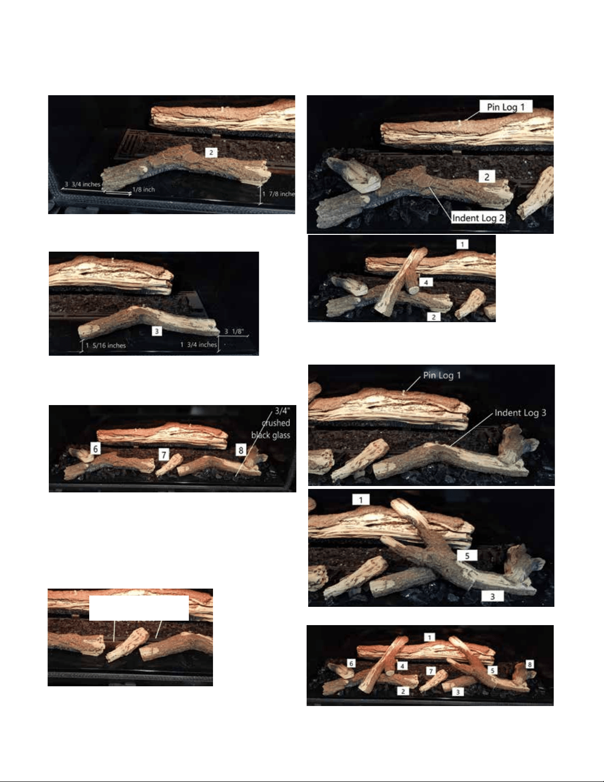
84 | City Series CC40E-11
installation
920-086 08.26.19
Completed Install
7. Position Log 2 as shown and follow the measurements. 11. Place Log 4—identify the pin locator and match with the left side
pin on Log 1. Rest the Log 4 on the indent in Log 2 as shown below.
9. Place Log 6, Log 7 and Log 8 on the burner locations shown below.
10. Before placing the next log—spread the optional media evenly
throughout the burner tray as shown.
NOTE: Ensure the installed optional media doesn't completely block the
air fl ow—ensure more than 50% of the airfl ow is open (shown with 3/4"
crushed black glass).
8. Place Log 3 to the right front corner of the burner. Follow the mea-
surement as shown.
12. Place Log 5—identify the pin locator and match with the right side
pin on Log 1. Rest the Log 5 on the indent in Log 3 as shown below.
Do not completely block
air fl ow
Log 2 in position
Log 3 in position
Log 4 in position
Log 5 in position
Log 6, 7, and 8 in position
2
CITY LINE
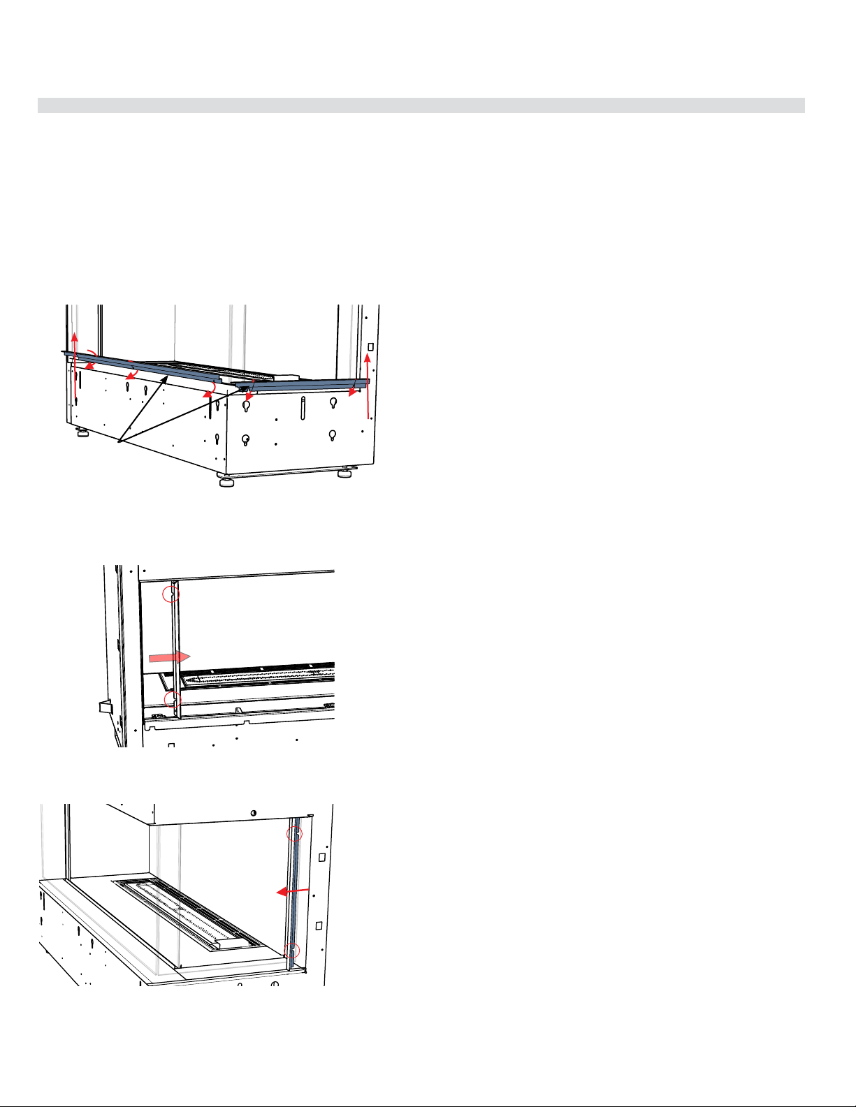
City Series CC40E-11 | 85
installation
Removable Drywall Guides
(when using 1/2" drywall)
An optional finishing trim is available to finish the edges of the installation on
the CC40RE/CC40LE unit. Installation is as follows:
1. Remove the outer safety glass and outer front and side panels - see in-
structions in manual.
2. Loosen 3 screws inside the lower front edge of the unit to release existing
lower drywall guide and remove guide.
Note : an offset screwdriver is provided with the appliance for ease of removal/
installation of the lip and finishing trim.
tooltip
tooltip
Loosen and tighten screws on drywall guide from inside front panel
Loosen 2 screws from inside the firebox to remove the side drywall trim
pieces
Lower drywall
guides
3. Loosen 2 screws from inside the firebox to release the existing side drywall
guide, remove guide and recycle.
4. Loosen 2 screws from inside the firebox to release the existing side drywall
guide, remove guide and recycle.
5. Reverse steps to reinstall drywall guides (if applicable). If discarding, please
recycle.
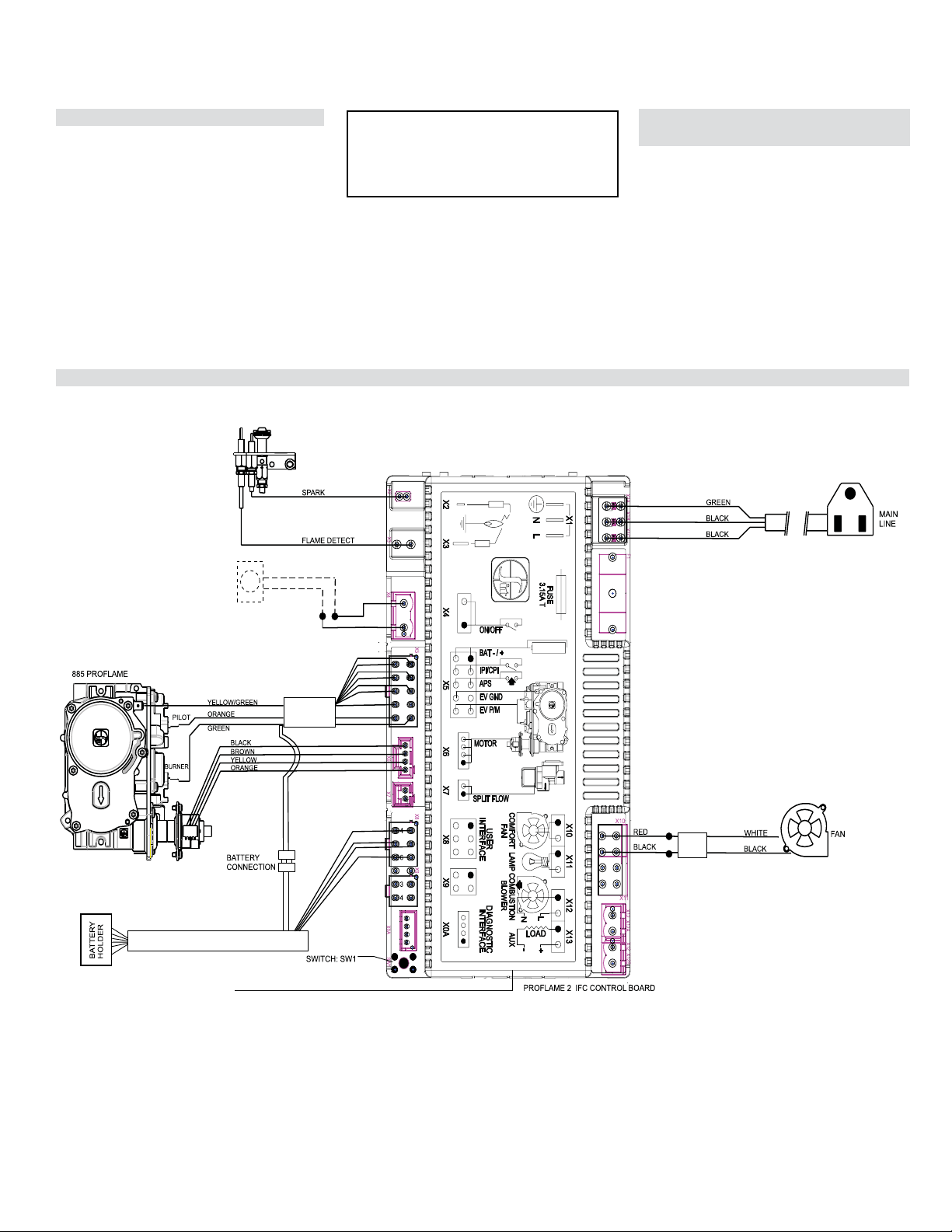
86 | City Series CC40E-11
installation
Optional Wall Thermostat
A wall thermostat may be installed if desired.
Connect the wires as per the wiring diagrams.
Note: Preferable if the thermostat is installed
on an interior wall.
Regency
®
offers an optional programmable
thermostat but any 250-750 millivolt rated non-
anticipator type thermostat that is CSA, ULC or
UL approved may be used.
CAUTION
Do not connect the millivolt
wall thermostat wires
to the 120V wires.
Wiring Diagram with Optional Thermostat
GREY
GREY
Thermostat( Optional)
(Millivolt)
EXTERNAL ANTENNA
Operation Using an Optional Wall
Thermostat
This unit ships with a full function remote control as
standard equipment. This allows for basic on/off
function as well as the ability to operate as a ther-
mostat. With the addition of an optional wall cradle
(820-477-AWT available from an authorized dealer)
the remote can reside on a wall and carry out all
the functions of a typical millivolt wall thermostat as
well as being able to control the fan speed, and the
flame height. This is the recommended procedure
for operating the unit with a thermostatic set point.
If a millivolt wall thermostat is required for bedroom
installation or as preferred method of controlling the
stove, see noted option.
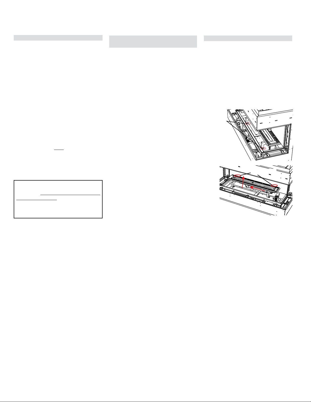
City Series CC40E-11 | 87
operating instructions
Aeration Adjustment
The burner aeration is factory set but may need
adjusting due to either the local gas supply or
altitude. Open the air shutter for a blue flame or
close for a more yellow flame.
1. Remove outer safety glass and inner glass
panels plus outer and inner base panels - see
instructions in this manual.
3. Reverse steps to reinstall burner.
Minimum Air Shutter Opening:
NG 1/16"
NG with Logs 1/16"
NG with Stones 1/16"
LP 3/8"
LP with Logs 3/8"
LP with Stones 3/8"
Note: Any damage due to carboning
resulting from improperly setting
the aeration controls is NOT covered
under warranty.
2. Loosen 4 screws in locations shown below (2 at
front and 2 at rear)—slide burner to the left away
from the orifice and lift out.
Front
screw locations
Back screw locations
Normal Operating Sounds of
Gas Appliances
It is possible that you will hear some sounds from
your gas appliance. This is perfectly normal due to
the fact that there are various gauges and types
of steel used within your appliance. Listed below
are some examples. All are normal operating
sounds and should not be considered as defects
in your appliance.
Burner Tray:
The burner tray is positioned directly under the
burner tube(s) media and logs and is made of a
different gauge material from the rest of the firebox
and body. Therefore, the varying thicknesses of
steel will expand and contract at slightly different
rates which can cause "ticking" and "cracking"
sounds. You should also be aware that as there
are temperature changes within the unit these
sounds will likely re-occur. Again, this is normal
for steel fireboxes.
Pilot Flame:
While the pilot flame is on it can make a very slight
"whisper" sound.
Gas Control Valve:
As the gas control valve turns ON and OFF, a
dull clicking sound may be audible, this is normal
operation of a gas regulator or valve.
Unit Body/Firebox:
Different types and thicknesses of steel will expand
and contract at different rates resulting in some
"cracking" and "ticking" sounds will be heard
throughout the cycling process.
During the first few fires, a white film may
develop on the glass front as part of the curing
process. The glass should be cleaned after the
unit has cooled down or the film will bake on
and become very difficult to remove. Use a
non-abrasive cleaner and DO NOT ATTEMPT
TO CLEAN THE GLASS WHILE IT IS HOT.
The FIRST FIRE in your fireplace is part of the paint
curing process. To ensure the paint is properly cured,
it is recommended you burn your fireplace for at
least four (4) hours the first time.
When first operated, the unit will release an odour
caused by the curing of the paint and the burning
off of any oils remaining from manufacturing. Smoke
detectors in the house may go off at this time. Open
a few windows to ventilate the room for a couple of
hours. The glass may require cleaning.
NOTE: When the glass is cold and the appli-
ance is lit, it may cause condensation
and fog the glass. This condensation
is normal and will disappear in a few
minutes as the glass heats up.
DO NOT ATTEMPT TO CLEAN THE GLASS
WHILE IT IS STILL HOT!
DO NOT BURN THE UNIT WITHOUT THE
GLASS IN PLACE.
First Fire
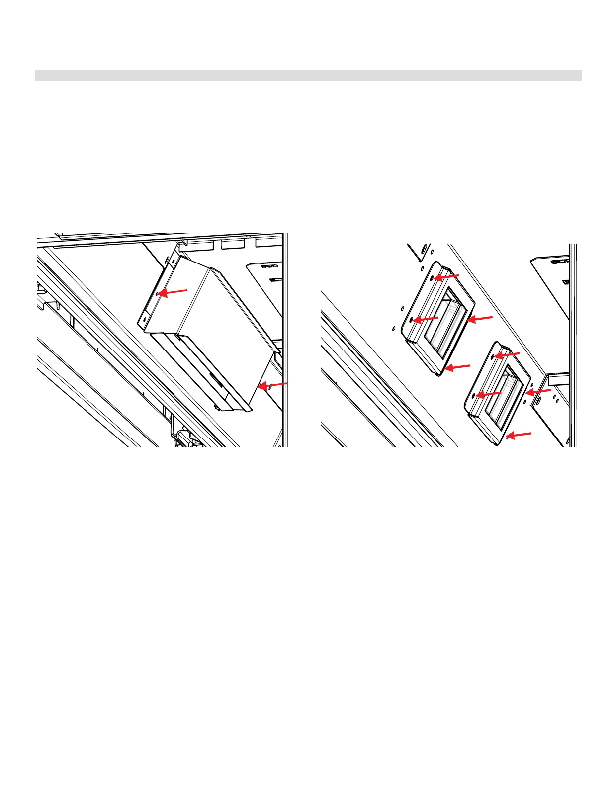
88 | City Series CC40E-11
maintenance
Bulb Replacement
1. Turn off unit and allow to cool to room temperature.
2. Remove outer safety glass panels and inner panels (firebox glass)–see
instructions in this manual.
3. Loosen 2 outer screws on each side to remove outer light cover — located
in the upper inside front of the firebox and remove.
4. Loosen 2 screws on each side of individual inner light cover and remove.
5. Remove glass cover by using a flat head screwdriver to pry the tab securing
the glass assembly in place.
6. Replace bulb and reverse steps to complete procedure.
NOTE: Do not handle bulb with bare hands. Use packaging or a tissue to hold
new bulb when replacing.
Regency Part# 911-208 Oven Lamp Assembly G9 120V/25W
Regency Part# 911-072 Replacement Bulb G9 120 Volt/25 watt
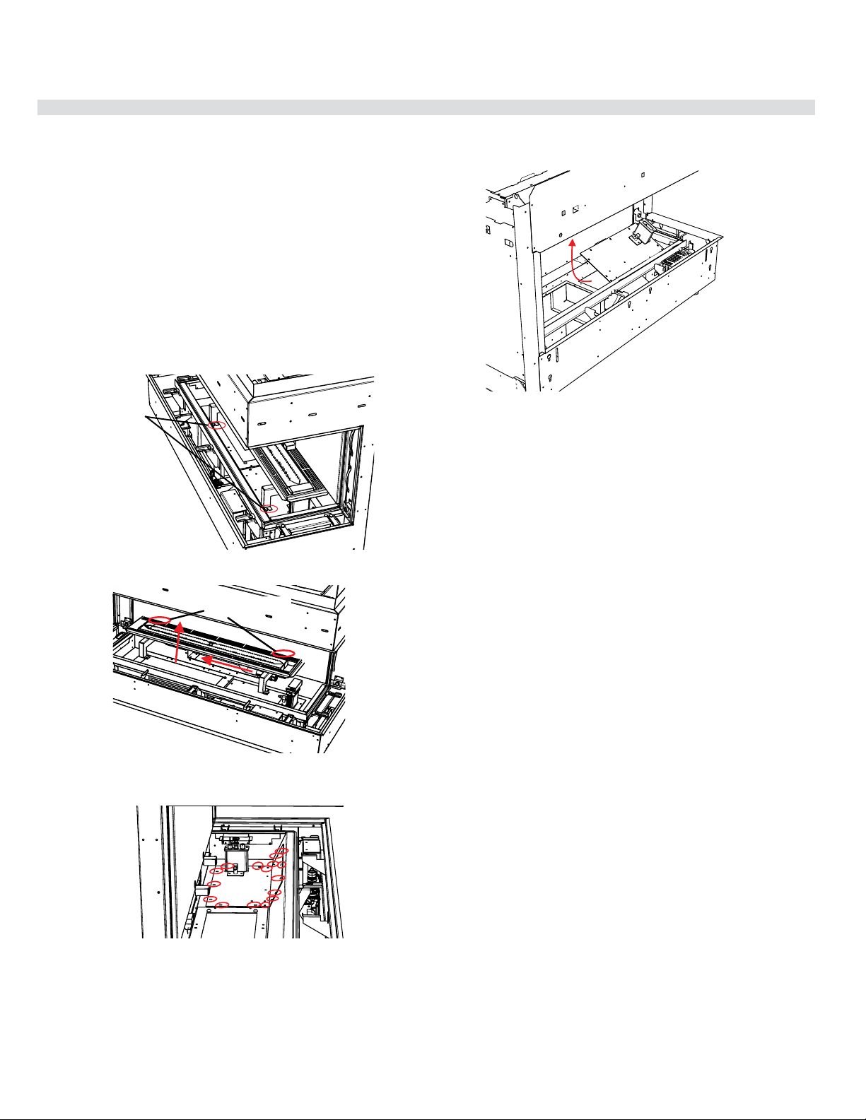
City Series CC40E-11 | 89
maintenance
Valve Replacement
Important: Always shut off gas supply/120 volt power prior to servicing the
gas valve.
1. Turn off unit and allow to cool to room temperature.
2. Remove outer enamel or steel panels—see instructions in the panel removal
section in this manual
3. Remove outer safety glass panels and inner panels (firebox glass)–see
instructions in this manual.
4. Remove all media and logs (if installed) — set aside.
6. Remove 16 screws in locations shown below.
7. Lift valve tray by out partially and disconnect flexible gas connection on the
valve inlet side, remove valve tray- replace with new valve tray.
8. Reverse steps 6-1 to complete.
tooltip
Remove 16 screws securing valve tray
5. Loosen 4 screws in locations shown below (2 at front and 2 at rear)—slide
burner to the left away from the orifice and lift out.
Front
screw locations
Back screw locations

90 | City Series CC40E-11
maintenance
Gas Maintenance - Recommended Annual Routine
Gas Maintenance
09.14.201920-324
Inspect
• Pilot assembly
• Burner
• Pressure relief gaskets/doors
• Flue connector gasket if present
• Door seal
• Firebox
• Venting
• Batteries (remote handheld, remote receiver,
DC sparker, change as needed)
• Burner media (change as needed)
• Air shutter setting
• Wiring
Clean
• Glass
• Interior bricks / panels
• Burner ports & burner air shutter
• Fan blades
• Log set
• Pilot orifices
• Pilot hood (change as needed)
• Flame sensor (electronic ignition models)
• Flame electrode
• Burner orifice
• Thermocouple (millivolt models)
• Thermopile (millivolt models)
Recommended Annual Routine Maintenance for Gas Fireplaces, Stoves and Inserts
In order for your Regency appliance to continue to provide comfort to your home periodic maintenance must be performed to ensure it is
operating at peak efficiency. The items in the list should be checked by a licensed gas service technician during the annual service check.
Your unit may require more frequent maintenance checks if you notice any changes in how it operates. Operational changes to look for
can include, but are not limited to, extended start up time, increased fan noise, residue/carbon build up, white build up on the glass/firebox,
increased operating noise etc. Should any of these or other conditions arise, discontinue use and schedule a service check with your
local licensed gas technician. The list below shows items your licensed service technician will need to check and service at least annually.
Check
• Voltage on thermocouple/thermopile (mil-
livolt models)
• Ohms reading on flame sense (electronic
ignition models)
• Inlet/outlet fuel pressures as per rating plate
• Voltage/ohms readings on gas valve
• Ohms reading to on/off switch circuit (Mili-
volt models)
Gas Leak Tests
• Check main gas line connection to valve
• Check shut off valve connections
• Check connection at gas valve outlet
• Check connection at main burner orifice
• Check pilot fuel line at valve and at pilot
assembly
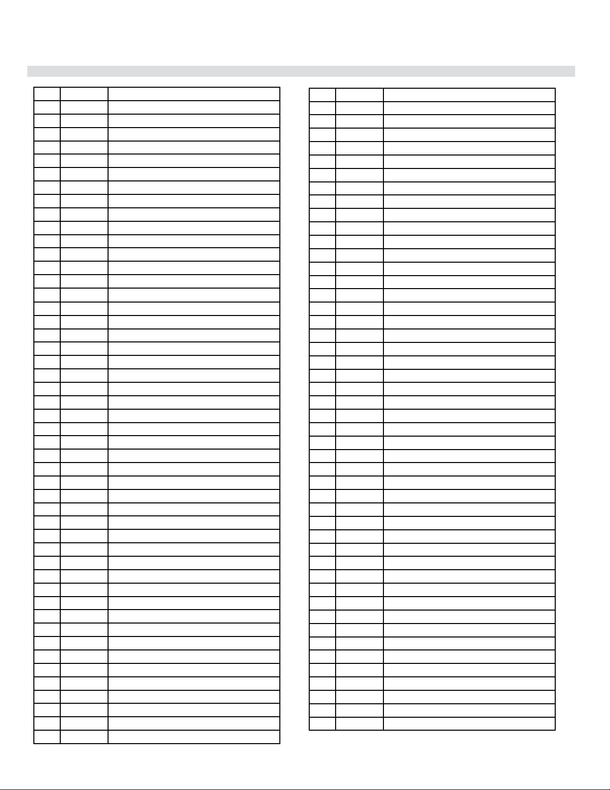
City Series CC40E-11 | 91
parts list
Main Assembly
1 657-525 Burner Assembly - NG/LP
2 656-046 Pilot Cover/Shield
4 911-276 Pilot Assembly IPI NG 2 Flame
4 911-277 Pilot Assembly IPI LP 2 Flame
5 911-188 Novasit Valve Only - NG 885 SIT IPI 0.885.009
5 911-189 Novasit Valve Only - LP 885 SIT IPI
6 657-276 IFC Cover/Shield
6A 911-266/P IFC Board Complete 584.625
7 656-045 Burner Surround
8 940-486/P Outer Barrier Tempered Glass Assembly - Large
9 940-436/P Flush Inner Ceramic Glass - Large
N/S 656-062 Outer Base Cover Black
10 940-440/P Outer Safety Glass Side - Tempered Small
11 940-437/P Flush Inner Ceramic Glass Small
17 656-574/P Valve Assembly - NG
17 656-776/P Valve Assembly - LP
18 656-033F Bottom Cover Access Plate
18 656-034 Bottom Cover Access Gasket
19 656-309 Removable Drywall Finishing
20 656-124 Removable Drywall Finishing Trim
22 911-190 Stepper Motor NG SIT 0.907.015
22 911-191 Stepper Motor LP SIT 0.907.015
23 656-125 Removable Drywall Vertical Finishing Trim Left/Right
24 656-241F Nailing Strip Side
25 656-247F Nailing Strip Top
N/S 936-219 Gasket 5/8 (09) Sewn Rope Graphite 3/4 PSA 10
(Sold per Foot 10 Feet Required)
N/S 904-943 Bracket Dormont Orifice Mount 10-BZ001-19.5
N/S 936-220 Gasket Tape 2" Wide Graphite Wrap
N/S 656-051 Baffle Cover (Each)
N/S 904-996 Burner Orifice #42 NG (PO512)
N/S 904-947 Burner Orifice #53 LP (PO512)
N/S 910-036 Pilot Orifice SIT - NG #51 977.165
N/S 910-037 Pilot Orifice SIT - LP #30 977.167
N/S 911-037 Flame Sensor 0.915.905
N/S 911-038 Flame Electrode 0.915.020
N/S 910-432 Novasit Pilot Tubing With Nuts
N/S 911-039 Two Way Pilot Hood
N/S 911-137 Pilot Hood Clip
N/S 904-658 Inlet Flex Line Gas SS Steel 24 inch
N/S 904-606 Fitting 90 Street Elbow Extruded
N/S 904-165 Fitting 3/8 Male Flarex Mpt Strt Adaptor
N/S W840470 Pilot Assembly Gasket
N/S 656-040 Valve Assembly Gasket
N/S 656-039 Burner Orifice Mount Gasket
N/S 911-175 Hand Held Remote Control GTMFL SIT 0.584.042
N/S 911-337/P Remote Receiver/Battery Holder 584.103
N/S 911-335 Cover Wall Mount White 0.584.813
N/S 911-343 Cover Wall Mount Black 0.584.812
N/S 911-173 Wire Harness IFC No CPI Switch 584.924
N/S 911-177 Wire 4 Position IFC Fan & Light
N/S 911-181 Wire Harness Battery Box Proflame II
N/S 911-192 Power Cord 120 Volts With Connector
N/S 911-193 Connector With Jumper
N/S 911-209 Wire 2 Position IFC to Lights
N/S 910-369 Receptacle Box Low Voltage SC100A
N/S 910-428 Receptacle Duplex White
N/S 910-429 Receptacle Box Duplex Metal
N/S 910-430 Receptacle Cover Duplex Metal
N/S 904-687 Connector Clamp 3/8 CI-804
N/S 948-078 Glass Suction Cup (Each)
N/S 904-790 Magnet Round 1/2 inch (Each)
N/S 904-970 Magnet Cup 1/2 inch (Each)
N/S 948-223 Logo Plate Plastic Regency/Flame Silver
N/S 656-550 Logo Mounting Bracket
N/S 656-017F Restrictor Plate
N/S 656-018 Pressure Relief Base
N/S 656-023 Pressure Relief Base Gasket
N/S 656-019 Pressure Relief Bracket Right
N/S 656-020 Pressure Relief Bracket Left
N/S 656-021F Pressure Relief Door
N/S 656-022 Pressure Relief Door Gasket
N/S 656-075F Rear Standoff (Each)
N/S 911-208 Oven Lamp Assembly G9 120V 25W
N/S 656-086 Light Glass Bracket
N/S 911-072 Replacement Bulb G9 120 Volt/25 watt
N/S 656-087 Light Rear Louver
N/S 656-088 Light Cover Plate
N/S 656-089 Light Deflector Shield
N/S 656-085 Gasket Light Cover Gasket
N/S 656-079 Top Glass Clamp Left (Each)
N/S 656-080 Top Glass Clamp Right (Each)
N/S 656-269 Lower Glass Clamp (Each)
N/S 656-052 Lower Glass Clamp Bracket (Each)
N/S 656-617 Pressure Relief Door Frame Assembly/Includes Gasket
Optional Accessories
11 656-926* Inner Panel Glass Black
11 656-927* Inner Panel Black (Painted)
11 656-928* Inner Panel Enamel Black
* Sold only as complete sets
N/S 656-202 Top Rear Panel Clip (Used on the 656-926)
N/S 656-203 Top Corner Bracket (Used on the 656-926)
N/S 656-205 Glass Panel Top Side Bracket (Used on the 656-926)
N/S 656-205 Lower Corner Glass Bracket (Used on the 656-926)
N/S 656-218 Rear Base Panel Bracket (Used on the 656-926)
N/S 656-291 Inner Top Panel Clip (Used on the 656-927)
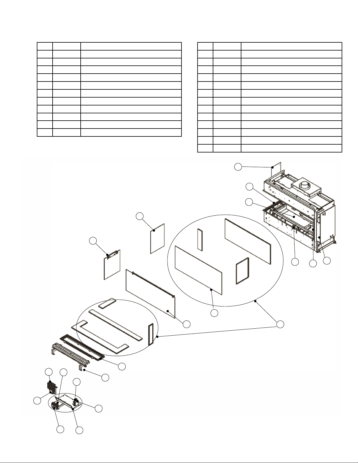
92 | City Series CC40E-11
parts list
9
20
18
19
12
8
11
10
7
1
4
17
5
2
22
6a
6
25
23
24
May not be exactly as shown
N/S 656-059 Inner Top Panel Clip (Used on the 656-928)
N/S 656-930/P Driftwood Log Set
N/S 657-977 Conversion Kit - LP
N/S 656-991 Chase Vent Front Black
N/S 656-995 Adaptor Heat Wave
N/S 946-556 Heatwave Kit
N/S 946-672 Stones - River Pebbles
N/S 946-674 Stones - Ceramic Spa (70 stones)
N/S 946-675 Fireglass Black Reflective 1/4in.1Lb Pkg
N/S 946-676 Fireglass Copper 1/4 in. 1Lb Pkg
N/S 946-677 Fireglass Starfire 1/4 in. 1Lb Pkg
N/S 946-775 Fireglass Black Reflective 1/4in.5Lb Pkg
N/S 946-776 Fireglass Copper 1/4 in. 5Lb Pkg
N/S 946-777 Fireglass Starfire 1/4 in. 5Lb Pkg
N/S 946-780 Crushed Glass Coal Black 3/4in. 3.5 Lbs
N/S 946-781 Crushed Glass Iceberg Chips 3/4in. 3.5 Lbs
N/S 946-735 Firebeads Black 1 Lb Pkg
N/S 946-736 Firebeads Sangria Luster 1 Lb Pkg
N/S 946-737 Firebeads Glacier Ice 1 Lb Pkg
N/S 946-738 Firebeads Caramel Luster 1 Lb Pkg
N/S 946-739 Firebeads Black 5 Lb Pkg
N/S 946-740 Firebeads Sangria Luster 5 Lb Pkg
N/S 946-741 Firebeads Glacier Ice 5 Lb Pkg
N/S 946-742 Firebeads Caramel Luster 5 Lb Pkg
N/S 946-710 Stones -Slate/Grey Basalt Natural 15 lbs
N/S 946-711 Stones - Ivory/Tan Basalt Natural 15 lbs
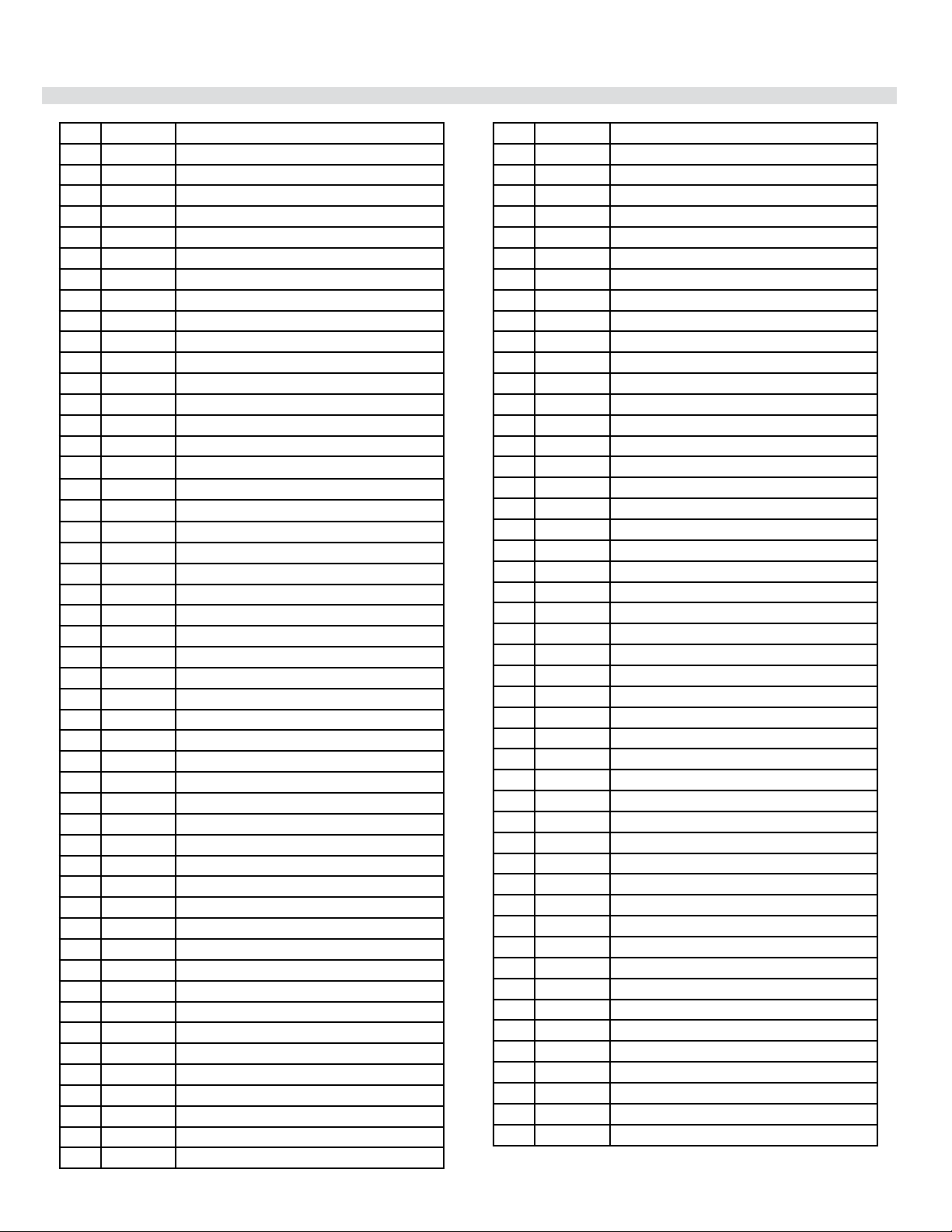
City Series CC40E-11 | 93
parts list
Main Assembly
1 657-525 Burner Assembly - NG/LP
2 656-046 Pilot Cover/Shield
4 911-006 Pilot Assembly IPI NG 2 Flame 0.199.050
4 911-277 Pilot Assembly IPI LP 2 Flame
5 911-188 Novasit Valve Only - NG 885 SIT IPI 0.885.009
5 911-189 Novasit Valve Only - LP 885 SIT IPI
6 657-009 IFC Cover/Shield
6A 911-266/P IFC Board Complete 584.625
7 656-045 Burner Surround
8 940-485/P Outer Barrier Tempered Glass Assembly - Large
9 940-436/P Flush Inner Ceramic Glass - Large
N/S 656-062 Outer Base Cover Black
10 940-439/P Outer Safety Glass Side - Tempered Small
11 940-437/P Flush Inner Ceramic Glass Small
12 936-219 Gasket 5/8 (09) Sewn Rope Graphite 3/4 PSA 10
(Sold per Foot 10 Feet Required)
N/S 936-220 Gasket Tape 2" Wide Graphite Wrap
17 656-574/P Valve Assembly - NG
17 656-776/P Valve Assembly - LP
18 656-033F Bottom Cover Access Plate
18 656-034 Bottom Cover Access Gasket
19 656-127 Removable Drywall Finishing Trim
20 656-293 Removable Drywall Finishing Trim
22 911-190 Stepper Motor NG SIT 0.907.015
22 911-191 Stepper Motor LP SIT 0.907.015
23 656-125 Removable Drywall Vertical Finishing Trim Left/Right
24 656-241F Nailing Strip Side
25 656-247F Nailing Strip Top
N/S 904-943 Bracket Dormont Orifice Mount 10-BZ001-19.5
N/S 656-051 Baffle Cover (Each)
N/S 904-996 Burner Orifice #42 NG (PO512)
N/S 904-947 Burner Orifice #53 LP (PO512)
N/S 910-100 Pilot Orifice SIT - NG #62 977.166
N/S 910-037 Pilot Orifice SIT - LP #30 977.167
N/S 911-037 Flame Sensor 0.915.905
N/S 911-038 Flame Electrode 0.915.020
N/S 910-432 Novasit Pilot Tubing With Nuts
N/S 911-039 Two Way Pilot Hood
N/S 911-137 Pilot Hood Clip
N/S 904-658 Inlet Flex Line Gas SS Steel 24 inch
N/S 904-606 Fitting 90 Street Elbow Extruded
N/S 904-165 Fitting 3/8 Male Flarex Mpt Strt Adaptor
N/S W840470 Pilot Assembly Gasket
N/S 656-040 Valve Assembly Gasket
N/S 656-039 Burner Orifice Mount Gasket
N/S 911-175 Hand Held Remote Control GTMFL SIT 0.584.042
N/S 911-337/P Remote Receiver/Battery Holder 584.103
N/S 911-335 Cover Wall Mount White 0.584.813
N/S 911-343 Cover Wall Mount Black 0.584.812
N/S 911-173 Wire Harness IFC No CPI Switch 584.924
N/S 911-177 Wire 4 Position IFC Fan & Light
N/S 911-181 Wire Harness Battery Box Proflame II
N/S 911-192 Power Cord 120 Volts With Connector
N/S 911-193 Connector With Jumper
N/S 911-209 Wire 2 Position IFC to Lights
N/S 910-369 Receptacle Box Low Voltage SC100A
N/S 910-428 Receptacle Duplex White
N/S 910-429 Receptacle Box Duplex Metal
N/S 910-430 Receptacle Cover Duplex Metal
N/S 904-687 Connector Clamp 3/8 CI-804
N/S 948-078 Glass Suction Cup (Each)
N/S 904-790 Magnet Round 1/2 inch (Each)
N/S 904-970 Magnet Cup 1/2 inch (Each)
N/S 948-223 Logo Plate Plastic Regency/Flame Silver
N/S 656-131 Logo Mounting Bracket
N/S 656-017F Restrictor Plate
N/S 656-018 Pressure Relief Base
N/S 656-023 Pressure Relief Base Gasket
N/S 656-019 Pressure Relief Bracket Right
N/S 656-020 Pressure Relief Bracket Left
N/S 656-021F Pressure Relief Door
N/S 656-022 Pressure Relief Door Gasket
N/S 656-075F Rear Standoff (Each)
N/S 911-208 Oven Lamp Assembly G9 120V 25W
N/S 656-086 Light Glass Bracket
N/S 911-072 Replacement Bulb G9 120 Volt/25 watt
N/S 656-087 Light Rear Louver
N/S 656-088 Light Cover Plate
N/S 656-089 Light Deflector Shield
N/S 656-085 Gasket Light Cover Gasket
N/S 656-079 Top Glass Clamp Left (Each)
N/S 656-080 Top Glass Clamp Right (Each)
N/S 656-269 Lower Glass Clamp (Each)
N/S 656-052 Lower Glass Clamp Bracket (Each)
N/S 656-617 Pressure Relief Door Frame Assembly/Includes Gasket
Optional Accessories
11 656-926* Inner Panel Glass Black
11 656-927* Inner Panel Black (Painted)
11 656-928* Inner Panel Enamel Black
* Sold only as complete sets
N/S 656-202 Top Rear Panel Clip (Used on the 656-926)
N/S 656-203 Top Corner Bracket (Used on the 656-926)
N/S 656-205 Glass Panel Top Side Bracket (Used on the 656-926)
N/S 656-205 Lower Corner Glass Bracket (Used on the 656-926)
N/S 656-218 Rear Base Panel Bracket (Used on the 656-926)
N/S 656-291 Inner Top Panel Clip (Used on the 656-927)
N/S 656-059 Inner Top Panel Clip (Used on the 656-928)
N/S 656-930/P Driftwood Log Set
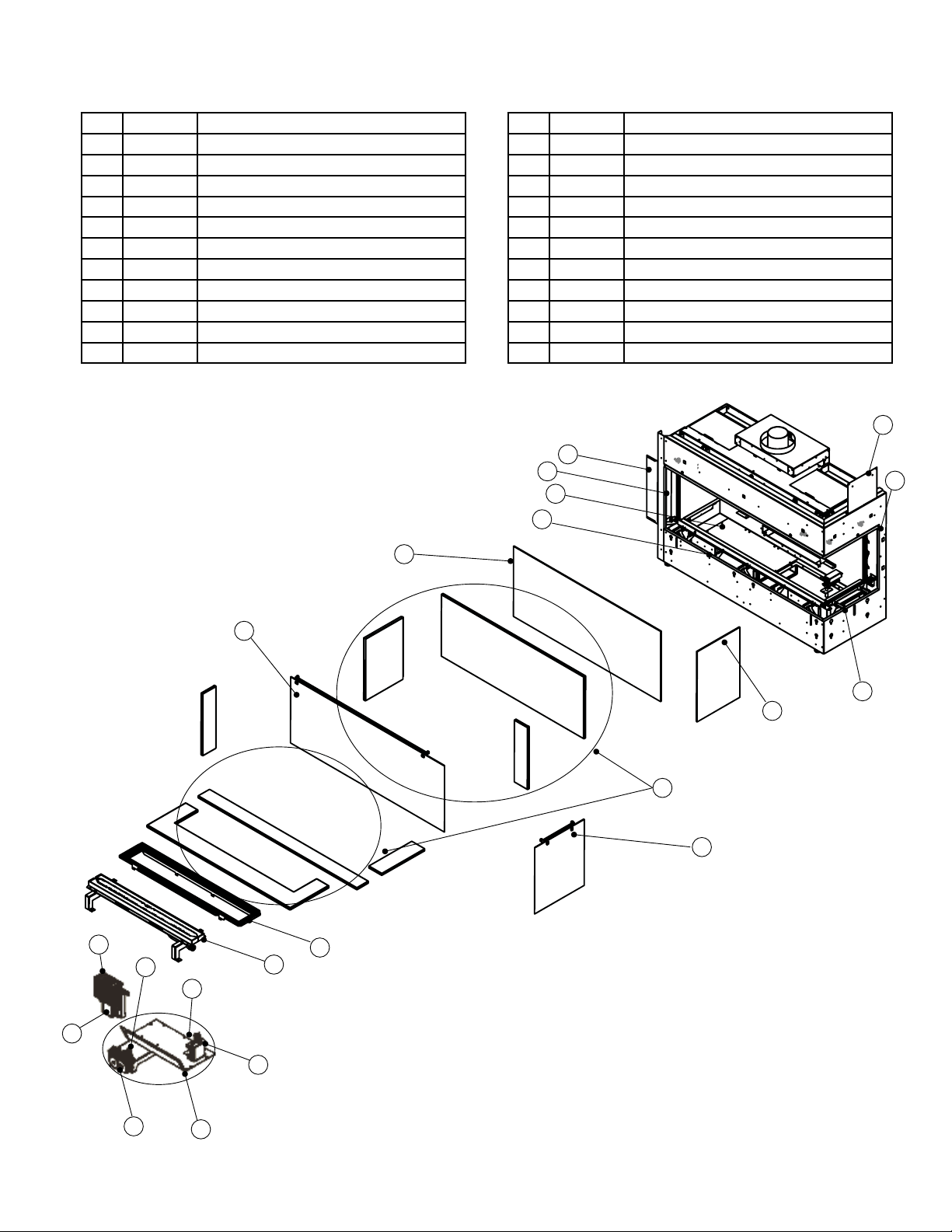
94 | City Series CC40E-11
parts list
4
17
5
22
6a
6
2
10
12
11
20
18
19
9
8
7
1
May not be exactly as shown
25
23
24
23
N/S 657-977 Conversion Kit - LP
N/S 656-991 Chase Vent Front Black
N/S 656-995 Adaptor Heat Wave
N/S 946-556 Heatwave Kit
N/S 946-672 Stones - River Pebbles
N/S 946-674 Stones - Ceramic Spa (70 stones)
N/S 946-675 Fireglass Black Reflective 1/4in.1Lb Pkg
N/S 946-676 Fireglass Copper 1/4 in. 1Lb Pkg
N/S 946-677 Fireglass Starfire 1/4 in. 1Lb Pkg
N/S 946-775 Fireglass Black Reflective 1/4in.5Lb Pkg
N/S 946-776 Fireglass Copper 1/4 in. 5Lb Pkg
N/S 946-777 Fireglass Starfire 1/4 in. 5Lb Pkg
N/S 946-780 Crushed Glass Coal Black 3/4in. 3.5 Lbs
N/S 946-781 Crushed Glass Iceberg Chips 3/4in. 3.5 Lbs
N/S 946-735 Firebeads Black 1 Lb Pkg
N/S 946-736 Firebeads Sangria Luster 1 Lb Pkg
N/S 946-737 Firebeads Glacier Ice 1 Lb Pkg
N/S 946-738 Firebeads Caramel Luster 1 Lb Pkg
N/S 946-739 Firebeads Black 5 Lb Pkg
N/S 946-740 Firebeads Sangria Luster 5 Lb Pkg
N/S 946-741 Firebeads Glacier Ice 5 Lb Pkg
N/S 946-742 Firebeads Caramel Luster 5 Lb Pkg
N/S 946-710 Stones -Slate/Grey Basalt Natural 15 lbs
N/S 946-711 Stones - Ivory/Tan Basalt Natural 15 lbs

City Series CC40E-11 | 95
notes
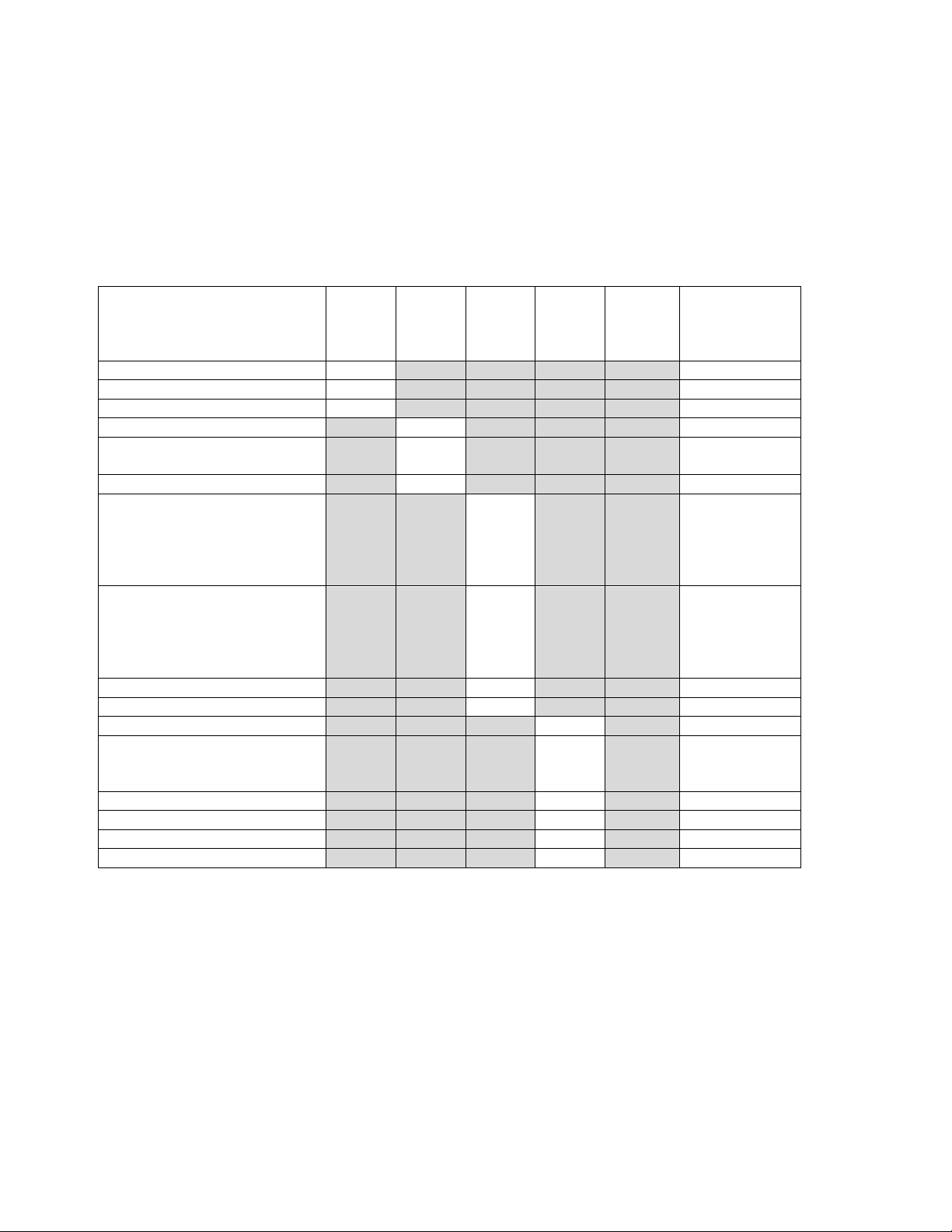
96 | City Series CC40E-11
warrant y
Revision Date: February 2019
Regency Gas Products Warranty
Limited Lifetime Warranty
FPI Fireplace Products International Ltd. (for Canadian customers) and Fireplace Products U.S., Inc. (for U.S.
customers) (collectively referred to herein as “FPI”) extends this Limited Lifetime Warranty to the original
purchaser of this appliance provided the product remains in the original place of installation. The items covered by
this limited warranty and the period of such coverage is set forth in the table below.
Some conditions apply (see below).
The policy is not transferable, amendable or negotiable under any circumstances.
Indoor Gas Products
Part
Supplier
Labor
Coverage
Warranty Coverage
Parts and Labor
Lifetime 5 years 2 years 1 year Warranty (Years)
Firebox and Heat Exchanger
3
Steel Burner Tube
3
Glass Thermal breakage only
3
All Surrounds/Inlays Finishes
3
Brick Panels/Log sets/Ceramic
Burners
3
All Castings
3
Valve assembly and all gas control
components, (Pilot assembly,
flame sensors, Spark Electrode,
Pilot Tubing, Orifices,
Thermocouple, Thermopile)
2
All Other Electrical
components,(Ignition Control
Boards, Wiring, Switches, Blowers,
Blower Control Module, Battery
Pack, Remote Control Systems)
2
Enamel Panels
1
Venting/Venting Components
1
All Stainless steel surrounds
1
All Firebox Media (Crystals,
Firebeads, Volcanic,
Ceramic & Spa Stones)
1
All hardware
1
Mesh/Glass Safety Barriers
1
Accent Light Bulbs
1
Glass (Crazing)
1
Conditions:
Warranty protects against defect in manufacture or FPI factory assembled components only, unless herein
specified otherwise.
Any part(s) found to be defective during the warranty period as outlined above will be repaired or replaced at FPI’s
option through an accredited distributor, dealer or pre-approved and assigned agent provided that the defective
part is returned to the distributor, dealer or agent for inspection if requested by FPI. Alternatively, FPI may at its
own discretion fully discharge all of its obligations under the warranty by refunding the verified purchase price of
the product to the original purchaser. The purchase price must be confirmed by the original Bill of Sale.
The authorized selling dealer, or an alternative authorized FPI dealer if pre-approved by FPI, is responsible for all
in-field diagnosis and service work related to all warranty claims. FPI is not responsible for results or costs of
workmanship of unauthorized FPI dealers or agents in the negligence of their service work.

City Series CC40E-11 | 97
warrant y
Revision Date: February 2019
Regency Gas Products Warranty
At all times FPI reserves the right to inspect reported complaints on location in the field claimed to be defective
prior to processing or authorizing of any claim. Failure to allow this upon request will void the warranty.
All warranty claims must be submitted by the dealer servicing the claim, including a copy of the Bill of Sale (proof
of purchase by you). All claims must be complete and provide full details as requested by FPI to receive
consideration for evaluation. Incomplete claims may be rejected.
Unit must be installed according to all manufacturers’ instructions as per the manual.
All Local and National required codes must be met.
The installer is responsible to ensure the unit is operating as designed at the time of installation.
The original purchaser is responsible for annual maintenance of the unit, as outlined in the owner’s manual. As
outlined below, the warranty may be voided due to problems caused by lack of maintenance.
Repair/replacement parts purchased by the consumer from FPI after the original coverage has expired on the unit
will carry a 90 day warranty, valid with a receipt only. Any item shown to be defective will be repaired or replaced
at our discretion. No labor coverage is included with these parts
Exclusions:
This Limited Lifetime Warranty does not extend to paint, rust or corrosion of any kind due to a lack of maintenance
or improper venting, combustion air provision, corrosive chemicals (i.e. chlorine, salt, air, etc.), door or glass
gasketing.
Malfunction, damage or performance based issues as a result of environmental conditions, location, chemical
damages, downdrafts, installation error, installation by an unqualified installer, incorrect chimney components
(including but not limited to cap size or type), operator error, abuse, misuse, use of improper fuels , lack of regular
maintenance and upkeep, acts of God, weather related problems from hurricanes, tornados, earthquakes, floods,
lightning strikes/bolts or acts of terrorism or war, which result in malfunction of the appliance are not covered
under the terms of this Limited Lifetime Warranty.
FPI has no obligation to enhance or modify any unit once manufactured (i.e. as products evolve, field modifications
or upgrades will not be performed on existing appliances).
This warranty does not cover dealer travel costs for diagnostic or service work. All labor rates paid to authorized
dealers are subsidized, pre-determined rates. Dealers may charge homeowner for travel and additional time
beyond their subsidy.
Any unit showing signs of neglect or misuse will not be covered under the terms of this warranty policy and may
void this warranty. This includes units with rusted or corroded fireboxes which have not been reported as rusted or
corroded within three (3) months of installation/purchase.
Units which show evidence of being operated while damaged, or with problems known to the purchaser and
causing further damages will void this warranty.
Units where the serial no. has been altered, deleted, removed or made illegible will void this warranty.
Minor movement, expansion and contraction of the steel is normal and is not covered under the terms of this
warranty.
FPI is not liable for the removal or replacement of facings or finishing in order to repair or replace any appliance in
the field.
Freight damages for products or parts are not covered under the terms of the warranty.
Products made or provided by other manufacturers and used in conjunction with the FPI appliance without prior
authorization from FPI may void this warranty.

98 | City Series CC40E-11
warrant y
Revision Date: February 2019
Regency Gas Products Warranty
Limitations of Liability:
The original purchaser’s exclusive remedy under this warranty, and FPI’s sole obligation under this warranty,
express or implied, in contract or in tort, shall be limited to replacement, repair, or refund, as outlined above. IN
NO EVENT WILL FPI BE LIABLE UNDER THIS WARRANTY FOR ANY INCIDENTAL OR CONSEQUENTIAL COMMERCIAL
DAMAGES OR DAMAGES TO PROPERTY. TO THE EXTENT PERMITTED BY APPLICABLE LAW, FPI MAKES NO EXPRESS
WARRANTIES OTHER THAN THE WARRANTY SPECIFIED HEREIN. THE DURATION OF ANY IMPLIED WARRANTY IS
LIMITED TO DURATION OF THE EXPRESSED WARRANTY SPECIFIED ABOVE. IF IMPLIED WARRANTIES CANNOT BE
DISCLAIMED, THEN SUCH WARRANTIES ARE LIMITED IN DURATION TO THE DURATION OF THIS WARRANTY.
Some U.S. states do not allow limitations on how long an implied warranty lasts, or allow exclusion or limitation of
incidental or consequential damages, so the above limitations or exclusions may not apply to you.
Customers located outside the U.S. should consult their local, provincial or national legal codes for additional
terms which may be applicable to this warranty.
How to Obtain Warranty Service:
Customers should contact the authorized selling dealer to obtain warranty service. In the event the authorized
selling dealer is unable to provide warranty service, please contact FPI by mail at the address listed below. Please
include a brief description of the problem and your address, email and telephone contact information. A
representative will contact you to make arrangements for an inspection and/or warranty service.
Canadian Warrantor:
FPI Fireplace Products International Ltd.
6988 Venture St.
Delta, British Columbia
Canada, V4G 1H4
U.S. Warrantor:
Fireplace Products U.S., Inc.
PO Box 2189 PMB 125
Blaine, WA
United States, 98231
Or contact the Regency Customer Care Centre at 1-800-442-7432 (phone) / 604-946-4349 (fax)
Product Registration and Customer Support:
Thank you for choosing a Regency Fireplace. Regency strives to be a world leader in the design, manufacture, and
marketing of hearth products. To provide the best support for your product, we request that you complete a
product registration form at http://www.regency-fire.com/Customer-Care/Warranty-Registration.aspx within
ninety (90) days of purchase.
City Series CC40E-11 | 99
warrant y
Product Registration and Customer Support:
Thank you for choosing a Regency Fireplace. Regency strives to be a world leader in the design, manufacture, and
marketing of hearth products. To provide the best support for your product, we request that you complete a product
registration form found on our Web Site under Customer Care within ninety (90) days of purchase.
For purchases made in CANADA or the UNITED STATES:
http://www.regency-fire.com/Customer-Care/Warranty-Registration.aspx
For purchases made in AUSTRALIA:
http://www.regency-fire.com.au/Customer-Care/Warranty-Registration.aspx
You may also complete the warranty registration form below to register your Regency Fireplace Product and mail and/or
fax it back to us, and we will register the warranty for you. It is important you provide us with all the information below in
order for us to serve you better.
Warranty Registration Form (or Register online immediately at the above Web Site):
Warranty Details
Serial Number (required):
Purchase Date (required) (mm/dd/yyyy):
Product Details
Product Model (required):
Dealer Details
Dealer Name (required):
Dealer Address:
Dealer Phone #:
Installer:
Date Installed (mm/dd/yyyy):
Your Contact Details (required)
Name:
Address:
Phone:
Email:
For purchases made in CANADA:
FPI Fireplace Products
International Ltd.
6988 Venture St.
Delta, British Columbia
Canada, V4G 1H4
Phone: 604-946-5155
Fax: 1-866-393-2806
For purchases made in the UNITED STATES:
Fireplace Products US, Inc.
PO Box 2189 PMB 125
Blaine, WA
United States, 98231
Phone: 604-946-5155
Fax: 1-866-393-2806
For purchases made in AUSTRALIA:
Fireplace Products Australia Pty
Ltd
1-3 Conquest Way
Hallam, VIC
Australia, 3803
Phone: +61 3 9799 7277
Fax: +61 3 9799 7822
For fireplace care and tips and answers to most common questions please visit our Customer Care section on our Web Site.
Please feel free to contact your selling dealer if you have any questions about your Regency product.

100 | City Series CC40E-11
warrant y

City Series CC40E-11 | 101
notes

102 | City Series CC40E-11
notes


© Copyright 2022, FPI Fireplace Products International Ltd. All rights reserved.
Installer: Please complete the following information
Dealer Name & Address: ____________________________________________________
___________________________________________________________________________
Installer: ___________________________________________________________________
Phone #: ___________________________________________________________________
Date Installed: ______________________________________________________________
Serial #: _______________________________________________________