1
VENT-FREE GAS
DUAL FUEL FIREPLACE
MODEL #VFF2-PH(20D)'+(20DB)(20D-C)(CPD-2T)
VFF2-PH(26D)(26DB)(26D-T)(IMD-2H)
VFF2-PH(32DR)(32DRB)(32DR-H)(FSDR-2C)
INSTALLER: Leave this manual with the appliance.
CONSUMER: Retain this manual for future reference.
WARNING: IF THE INFORMATION IN THIS MANUAL IS NOT FOLLOWED
EXACTLY, A FIRE OR EXPLOSION MAY RESULT CAUSING PROPERTY
DAMAGE, PERSONAL INJURY OR LOSS OF LIFE.
CAUTION - FOR YOUR SAFETY
Questions, problems, missing parts? Before returning to your retailer, call our customer
service department at 1-877-447-4768, 8:00 a.m. – 4:30 p.m., CST, Monday – Friday or
email us at [email protected].
WARNING: This appliance
is equipped for (Natural and
Propane) gas. Field conversion
is not permitted other than
between natural or propane
gases.
'RQRWVWRUHRUXVHJDVROLQHRURWKHUÀDPPDEOHYDSRUVDQG,LTXLGVLQYLFLQLW\RIWKLVRU
DQ\RWKHUDSSOLDQFH
WHAT TO DO IF YOU SMELL GAS
'RQRWWU\WROLJKWDQ\DSSOLDQFH
'RQRWWRXFKDQ\HOHFWULFDOVZLWFKGRQRWXVHDQ\SKRQHLQ\RXUEXLOGLQJ
,PPHGLDWHO\FDOO\RXUJDVVXSSOLHUIURPDQHLJKERU¶VSKRQH)ROORZWKHJDVVXSSOLHU¶V
LQVWUXFWLRQV
,I\RXFDQQRWUHDFK\RXUJDVVXSSOLHUFDOOWKH¿UHGHSDUWPHQW
,QVWDOODWLRQDQGVHUYLFHPXVWEHSHUIRUPHGE\DTXDOL¿HGLQVWDOOHUVHUYLFHDJHQF\RUWKH
JDVVXSSOLHU
7KLVLVDQXQYHQWHGJDV¿UHGKHDWHU,WXVHVDLUR[\JHQIURPWKHURRPLQZKLFKLWLV
LQVWDOOHG3URYLVLRQVIRUDGHTXDWHFRPEXVWLRQDQGYHQWLODWLRQDLUPRVWEHSURYLGHG
5HIHUWR$LU)RU&RPEXVWLRQDQG9HQWLODWLRQVHFWLRQRQSDJHRIWKLVPDQXDO
7KLVDSSOLDQFHPD\EHLQVWDOOHGLQDQDIWHUPDUNHWSHUPDQHQWO\ORFDWHGPDQXIDFWXUHGPRELOH
KRPHZKHUHQRWSURKLELWHGE\ORFDOFRGHV7KLVDSSOLDQFHLVRQO\IRUXVHZLWKSURSDQHRU
QDWXUDOJDV7KLVDSSOLDQFHLVHTXLSSHGZLWKDVLPSOHPHDQVWRVZLWFKEHWZHHQSURSDQHDQG
QDWXUDOJDV)LHOGFRQYHUVLRQE\DQ\RWKHUPHDQVLQFOXGLQJWKHXVHRIDNLWLVQRWSHUPLWWHG
&86
&86
$16=
Dual Fuel
NG LP
Patent Pending Dual
Fuel System
80-10-451 - 2021-02-16
ANS Z21.11.2-2019
2
:$51,1*'RQRWDWWHPSWWRDFFHVVRUFKDQJHWKHVHWWLQJRIWKHIXHOVHOHFWLRQPHDQV
$FFHVVWRDQGDGMXVWPHQWRIWKHIXHOVHOHFWLRQPHDQVPXVWRQO\EHDSHUIRUPHGE\D
TXDOL¿HGVHUYLFHSHUVRQZKHQFRQQHFWLQJWKLVDSSOLDQFHWRDVSHFL¿HGIXHOVXSSO\DW
WKHWLPHRILQVWDOODWLRQ
&KDQJHRIWKHVHOHFWRUVHWWLQJWRRWKHUWKDQWKHIXHOW\SHVSHFL¿HGDWWKHWLPHRI
LQVWDOODWLRQFRXOGGDPDJHWKLVDSSOLDQFHDQGUHQGHULWLQRSHUDEOH
7KHLQVWDOOHUVKDOOUHSODFHWKHDFFHVVFRYHUEHIRUHFRPSOHWLQJWKHLQVWDOODWLRQDQG
RSHUDWLQJWKLVDSSOLDQFH
WARNING: $Q\VDIHW\VFUHHQRUJXDUGUHPRYHGIRUVHUYLFLQJDQDSSOLDQFH
PXVWEHUHSODFHGSULRUWRRSHUDWLQJWKHKHDWHUVHH&ODXVH
WARNING: :KHQWKHDSSOLDQFHLVLQVWDOOHGGLUHFWO\RQFDUSHWLQJWLOHRURWKHU
FRPEXVWLEOHPDWHULDORWKHUWKDQZRRGÀRRULQJWKHDSSOLDQFHVKDOOEHLQVWDOOHG
RQDPHWDORUZRRGSDQHOH[WHQGLQJWKHIXOOZLGWKDQGGHSWKRIWKHDSSOLDQFH
3
WARNING: Read the Installation & Operating Instructions before using this appliance.
IMPORTANT: Read all instructions and warnings carefully before starting installation.
Failure to follow these instructions may result in possible injury to persons or a fire
hazard and will void the warranty.
TABLE OF CONTENTS
6SHFL¿FDWLRQV ................................................................................................................................... 3
Important Safety Information ............................................................................................................4
3URGXFW,GHQWL¿FDWLRQ........................................................................................................................ 6
Product Features.............................................................................................................................. 7
Unpacking......................................................................................................................................... 7
Hood Assembly................................................................................................................................. 8
Preparing for Installation................................................................................................................... 9
Installation ...................................................................................................................................... 12
Operation........................................................................................................................................ 24
Remote Control Operation...............................................................................................................27
Care and Maintenance ................................................................................................................... 33
Troubleshooting.............................................................................................................................. 36
Replacement Parts......................................................................................................................... 38
Accessories .................................................................................................................................... 39
Warranty ......................................................................................................................................... 42
6(59,&(+,176
:KHQ*DV3UHVVXUH,V7RR/RZ
• pilot will not stay lit
• burners will have delayed ignition
¿UHSODFHZLOOQRWSURGXFHVSHFL¿HGKHDW
• for propane/LP units, propane/LP gas supply may be low
You may feel your gas pressure is too low. If so, contact your local natural or propane/LP gas supplier.
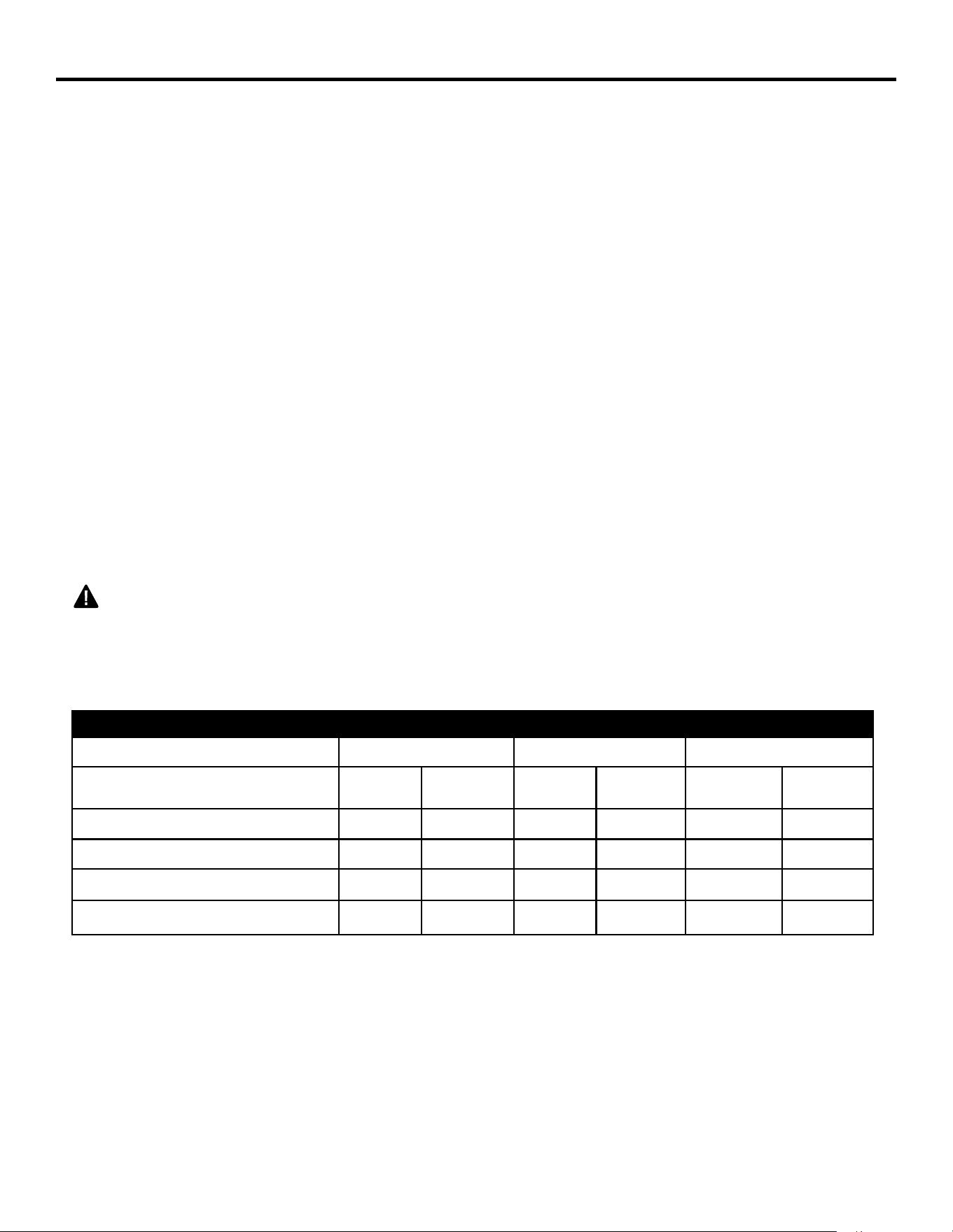
0RGHO
9))3+&36HULHV 9))3+,06HULHV 9))3+)66HULHV
Input Rating 20,000 BTU/Hr 30,000 BTU/Hr 33,000 BTU/Hr
Minimum Input Rating
16,000
BTU/Hr
10,000
BTU/Hr
24,000
BTU/Hr
15,000
BTU/Hr
33,000
BTU/Hr
33,000
BTU/Hr
Gas Type LP NG LP NG LP NG
Manifold Pressure 10" W.C. 5" W.C. 10" W.C. 5" W.C. 10" W.C. 5" W.C.
Max. Inlet Pressure 14" W.C. 14" W.C. 14" W.C. 14" W.C. 14" W.C. 14" W.C.
Min. Inlet Pressure 11" W.C. 6" W.C. 11" W.C. 6" W.C. 11" W.C. 6" W.C.
4
IMPORTANT: Read this owner’s manual carefully and completely before trying to assemble, operate,
RUVHUYLFHWKLVKHDWHU,PSURSHUXVHRIWKLVKHDWHUFDQFDXVHVHULRXVLQMXU\RUGHDWKIURPEXUQV¿UH
explosion, electrical shock, and carbon monoxide poisoning.
IMPORTANT SAFETY INFORMATION
2QO\DTXDOL¿HGLQVWDOOHUVHUYLFHDJHQWRUORFDOJDVVXSSOLHUPD\LQVWDOODQGVHUYLFHWKLVSURGXFW
WARNING:'RQRWVWRUHRUXVHJDVROLQHRURWKHUÀDPPDEOHYDSRUVRUOLTXLGVLQWKHYLFLQLW\
of this or any other appliance.
:$51,1*7KLVDSSOLDQFHFDQEHXVHGZLWKSURSDQHRUQDWXUDOJDV,WLVVKLSSHGIURPWKH
IDFWRU\DGMXVWHGIRUXVHZLWKSURSDQH
CARBON MONOXIDE POISONING: (DUO\VLJQVRIFDUERQPRQR[LGHSRLVRQLQJUHVHPEOHWKHÀX
with headaches, dizziness, or nausea. If you have these signs, the heater may not be working properly.
*HWIUHVKDLULPPHGLDWHO\+DYHKHDWHUVHUYLFHG6RPHSHRSOHDUHPRUHDႇHFWHGE\FDUERQPRQR[LGH
than others. These include pregnant women, people with heart or lung disease, people who are
DQHPLFWKRVHXQGHUWKHLQÀXHQFHRIDOFRKRODQGWKRVHOLYLQJLQKLJKDOWLWXGHV
1$785$/$1'3523$1(/3*$6 Natural and Propane/LP gases are odorless. An odor-making
agent is added to the gas. The odor helps you detect a gas leak. However, the odor added to the
gas can fade. Gas may be present even though no odor exists. Make certain you read and under-
stand all warnings. Keep this manual for reference. It is your guide to operating this heater safely.
WARNING:$Q\FKDQJHWRWKLV¿UHSODFHKHDWHURULWVFRQWUROVFDQEHGDQJHURXV
WARNING: Do not use any accessories not approved for use with this heater.
WARNING: &DUHIXOO\VXSHUYLVH\RXQJFKLOGUHQZKHQWKH\DUHLQWKHURRPZLWKWKHKHDWHU
WARNING: Heater becomes very hot when operating. Keep children and adults away from hot
VXUIDFHVWRDYRLGEXUQVRUFORWKLQJLJQLWLRQ+HDWHUZLOOUHPDLQKRWIRUDWLPHDIWHUVKXWRႇ$OORZ
surfaces to cool before touching.
WARNING: Keep the appliance area clear and free from combustible materials, gasoline, and
RWKHUÀDPPDEOHYDSRUVDQGOLTXLGV
WARNING:'XHWRKLJKWHPSHUDWXUHVORFDWHWKLVDSSOLDQFHRXWRIWUDႈFDQGDZD\IURP
furniture and draperies.
WARNING:'RQRWSODFHFORWKLQJRURWKHUÀDPPDEOHPDWHULDORQRUQHDUWKHDSSOLDQFH1HYHU
place any objects in the heater.
WARNING
This product and the fuels used to operate this product (liquid propane or natural gas), and the products of combustion
of such fuels, can expose you to chemicals including benzene, which is known to the State of California to cause cancer
and reproductive harm.
For more information go to www.p65Warnings.ca.gov
WARNING: FIRE, EXPLOSION, AND ASPHYXIATION HAZARD
Improper adjustment, alteration, service, maintenance, or installation of this heater or its controls can
cause death or serious injury.
Read and follow instructions and precautions in User's Information Manual provided with this heater.

5
SAFETY INFORMATION
1. This appliance is only for use with the type of gas indicated on the rating plate. This appliance is
not convertible for use with other gases.
2.
Do not place propane/LP supply tank(s) inside any structure. Locate propane/LP supply tank(s) outdoors.
3. If you smell gas
VKXWRႇJDVVXSSO\
• do not try to light any appliance
• do not touch any electrical switch; do not use any phone in your building
• immediately call your gas supplier from a neighbor’s phone. Follow the gas supplier’s instructions
LI\RXFDQQRWUHDFK\RXUJDVVXSSOLHUFDOOWKH¿UHGHSDUWPHQW
7KLV¿UHSODFHVKDOOQRWEHLQVWDOOHGLQDEHGURRPRUEDWKURRP
'RQRWXVHWKLV¿UHSODFHDVDZRRGEXUQLQJ¿UHSODFH8VHRQO\WKHORJVSURYLGHGZLWKWKH¿UHSODFH
6. Do not add extra logs or ornaments such as pine cones, vermiculite or rock wool. Using these
added items can cause sooting. Do not add lava rock around base. Rock and debris could fall into
WKHFRQWURODUHDRI¿UHSODFH
7KLV¿UHSODFHLVGHVLJQHGWREHVPRNHOHVV,IORJVHYHUDSSHDUWRVPRNHWXUQRႇ¿UHSODFHDQG
FDOODTXDOL¿HGVHUYLFHSHUVRQ1RWH'XULQJLQLWLDORSHUDWLRQVOLJKWVPRNLQJFRXOGRFFXUGXHWRORJ
FXULQJDQG¿UHSODFHEXUQLQJPDQXIDFWXULQJUHVLGXHV
8. To prevent the creation of soot, follow the instructions in Cleaning and Maintenance, page 32.
%HIRUHXVLQJIXUQLWXUHSROLVKZD[FDUSHWFOHDQHURUVLPLODUSURGXFWVWXUQ¿UHSODFHRႇ,IKHDWHG
the vapors from these products may create a white powder residue within burner box or on adjacent
walls or furniture.
7KLV¿UHSODFHQHHGVIUHVKDLUYHQWLODWLRQWRUXQSURSHUO\7KLV¿UHSODFHKDVDQ2[\JHQ'HSOHWLRQ
6HQVLQJ2'6VDIHW\VKXWRႇV\VWHP7KH2'6VKXWVGRZQWKH¿UHSODFHLIQRWHQRXJKIUHVKDLULV
DYDLODEOH6HH$LUIRU&RPEXVWLRQDQG9HQWLODWLRQSDJH,I¿UHSODFHNHHSVVKXWWLQJRႇVHH
Troubleshooting, page 34.
'RQRWUXQ¿UHSODFH
ZKHUHÀDPPDEOHOLTXLGVRUYDSRUVDUHXVHGRUVWRUHG
• under dusty conditions.
'RQRWXVHWKLV¿UHSODFHWRFRRNIRRGRUEXUQSDSHURURWKHUREMHFWV
1HYHUSODFHDQ\REMHFWVLQWKH¿UHSODFHRURQORJV
'RQRWXVH¿UHSODFHLIDQ\SDUWKDVEHHQXQGHUZDWHU,PPHGLDWHO\FDOODTXDOL¿HGVHUYLFHWHFKQLFLDQ
WRLQVSHFWWKHURRP¿UHSODFHDQGWRUHSODFHDQ\SDUWRIWKHFRQWUROV\VWHPDQGDQ\JDVFRQWUROZKLFK
has been under water.
7XUQRႇDQGXQSOXJ¿UHSODFHDQGOHWFRROEHIRUHVHUYLFLQJ2QO\DTXDOL¿HGVHUYLFHSHUVRQ
VKRXOGVHUYLFHDQGUHSDLU¿UHSODFH
2SHUDWLQJ¿UHSODFHDERYHHOHYDWLRQVRIIHHWFRXOGFDXVHSLORWRXWDJH
17.
'RQRWRSHUDWH¿UHSODFHLIORJLVEURNHQ'RQRWRSHUDWH¿UHSODFHLIORJLVFKLSSHGGLPHVL]HGRUODUJHU
18. To prevent performance problems, do not use propane/LP fuel tank of less than 100 lb. capacity.
19. Provide adequate clearances around air openings.
QUALIFIED INSTALLING AGENCY
2QO\DTXDOL¿HGDJHQF\VKRXOGLQVWDOODQG
replace gas piping, gas utilization equip-
ment or accessories, and repair and equip-
PHQWVHUYLFLQJ7KHWHUPTXDOL¿HGDJHQF\
PHDQVDQ\LQGLYLGXDO¿UPFRUSRUDWLRQRU
company that either in person or through a
representative is engaged in and is respon-
sible for:
a) Installing, testing, or replacing gas piping or
b)Connecting, installing, testing, repairing, or
servicing equipment; that is experienced in
such work; that is familiar with all precautions
required; and that has complied with all the re-
quirements of the authority having jurisdiction.
6
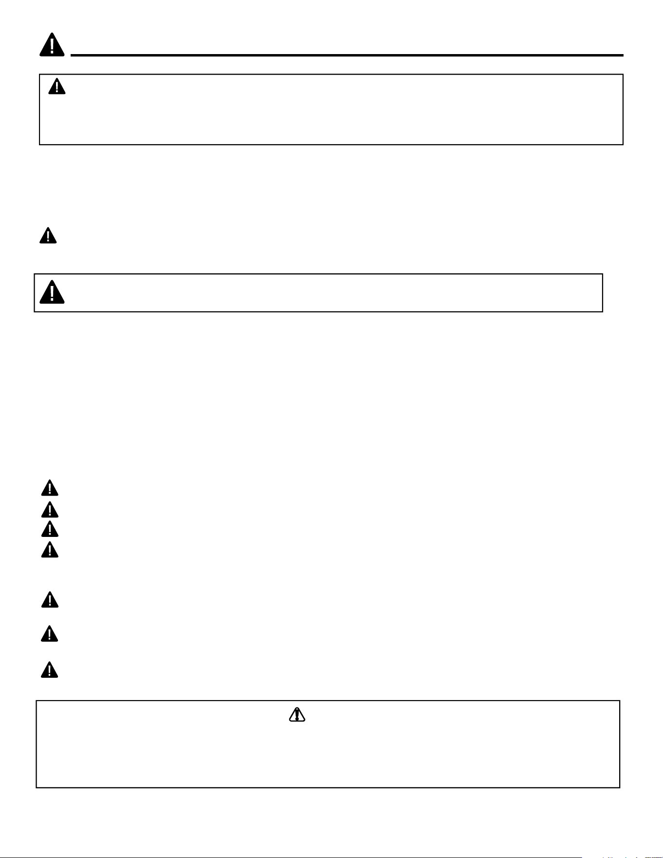
Screen
Log
Ignitor Button
Hood
Fireplace
Cabinet
Control Knob
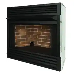
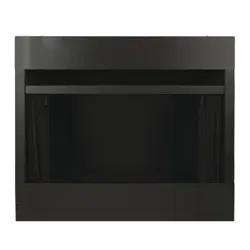
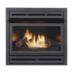
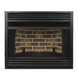
PRODUCT IDENTIFICATION
Screen
Log
Ignitor Button
Hood
Fireplace
Cabinet
Control Knob EI Receiver
Remote
Transmitter
Mantel
Cabinet
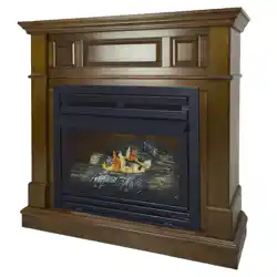
WARNING: 7KLV¿UHSODFHLVGHVLJQHGIRUXVHZLWKWKHPDQWHOFDELQHWSURYLGHG,QVWDOOLQJ
WKH¿UHSODFHFDELQHWZLWKRXWWKHSURYLGHGPDQWHORUVXEVWLWXWLQJDQRWKHUPDQWHOZLOOYRLGWKH
ZDUUDQW\DQGFRXOGUHVXO\LQSURSHUW\GDPDJHDQGSHUVRQDOLQMXU\
Fig. 1 - Vent-Free Dual Fuel Fireplace
VFF2-PH(32DR)(32DRB)(32DR-H)(FSDR-2C)
VFF2-PH(26D)(26DB)(26D-T)(IMD-2H)
VFF2-PH(20D)(20DB)(20D-C)(CPD-2T)
127(7KH¿UHSODFHLVLQVWDOOHGLQWRWKHPDQWHOWKURXJKWKHIURQWRSHQLQJRIWKHPDQWHOFDELQHW

7
UNPACKING
5HPRYH¿UHSODFHFDELQHWDQGKRRGIURPFDUWRQ/RJLVZUDSSHGDQGLQVLGH¿UHSODFH
Do not remove at this time.
5HPRYHDOOSURWHFWLYHSDFNDJLQJDSSOLHGWR¿UHSODFHIRUVKLSPHQW
0DNHVXUH\RXU¿UHSODFHLQFOXGHVRQHKDUGZDUHSDFNHW
&KHFN¿UHSODFHIRUDQ\VKLSSLQJGDPDJH,I¿UHSODFHLVGDPDJHGFDOO*+3*URXS,QFDW
447-4768. Please do not return it to the store.
SAFETY PILOT
7KLVKHDWHUKDVDSLORWZLWKDQ2[\JHQ'HSOHWLRQ6HQVLQJ2'6VDIHW\VKXWRႇV\VWHP
7KH2'6SLORWVKXWVRႇWKHKHDWHULIWKHUHLVQRWHQRXJKIUHVKDLUDQGFXWVRႇPDLQEXUQHUJDVLQWKH
HYHQWRIÀDPHRXW
ELECTRIC PUSH BUTTON IGNITION SYSTEM
This heater is equipped with an electronic push button control system. This system requires
one AAA battery (provided).
THERMOSTAT HEAT CONTROL
7KHFRQWURODXWRPDWLFDOO\F\FOHVWKHEXUQHURQDQGRႇWRPDLQWDLQDGHVLUHGURRP
temperature. See page 24.
DUAL FUEL CAPABILITY
Your heater is equipped to operate on either propane or natural gas. The heater is
shipped from the factory ready for connecting to propane. The heater can easily be
FKDQJHGWRQDWXUDOJDVE\KDYLQJ\RXUTXDOL¿HGLQVWDOOHUIROORZWKHLQVWUXFWLRQVRQSDJH
17 and the markings on the heater.
%/2:(5.,7237,21$/
The blower kit helps to distribute the warmed air into the space more rapidly.
6WDWHRI0DVVDFKXVHWWV7KHLQVWDOODWLRQPXVWEHPDGHE\DOLFHQVHGSOXPEHURUJDV¿WWHULQ
WKH&RPPRQZHDOWKRI0DVVDFKXVHWWV6HOOHUVRIXQYHQWHGSURSDQHRUQDWXUDOJDV¿UHG
VXSSOHPHQWDOURRPKHDWHUVVKDOOSURYLGHWRHDFKSXUFKDVHUDFRS\RI&05XSRQVDOH
RIWKHXQLW
,QWKH6WDWHRI0DVVDFKXVHWWVXQYHQWHGSURSDQHRUQDWXUDOJDV¿UHGVSDFHKHDWHUVVKDOO
EHSURKLELWHGLQEHGURRPVDQGEDWKURRPV
,QWKH6WDWHRI0DVVDFKXVHWWVWKHJDVFRFNPXVWEHD7KDQGOHW\SH7KH6WDWHRI
0DVVDFKXVHWWVUHTXLUHVWKDWDÀH[LEOHDSSOLDQFHFRQQHFWRUFDQQRWH[FHHGWKUHHIHHW
in length.
LOCAL CODES
Install and use heater with care. Follow all codes. In the absence of local codes, use the latest edi-
tion of The National Fuel Gas Code, ANSI Z223.1, also known as NFPA 54*.
*Available from:
American National Standard Institute, Inc. National Fire Protection Association, Inc.
1430 Broadway 1 Batterymarch Park
New York, NY 10018 Quincy, MA 02269-9101
This heater is designed for vent-free operation. State and local codes in some areas prohibit the use
of vent-free heaters.
PRODUCT FEATURES
8
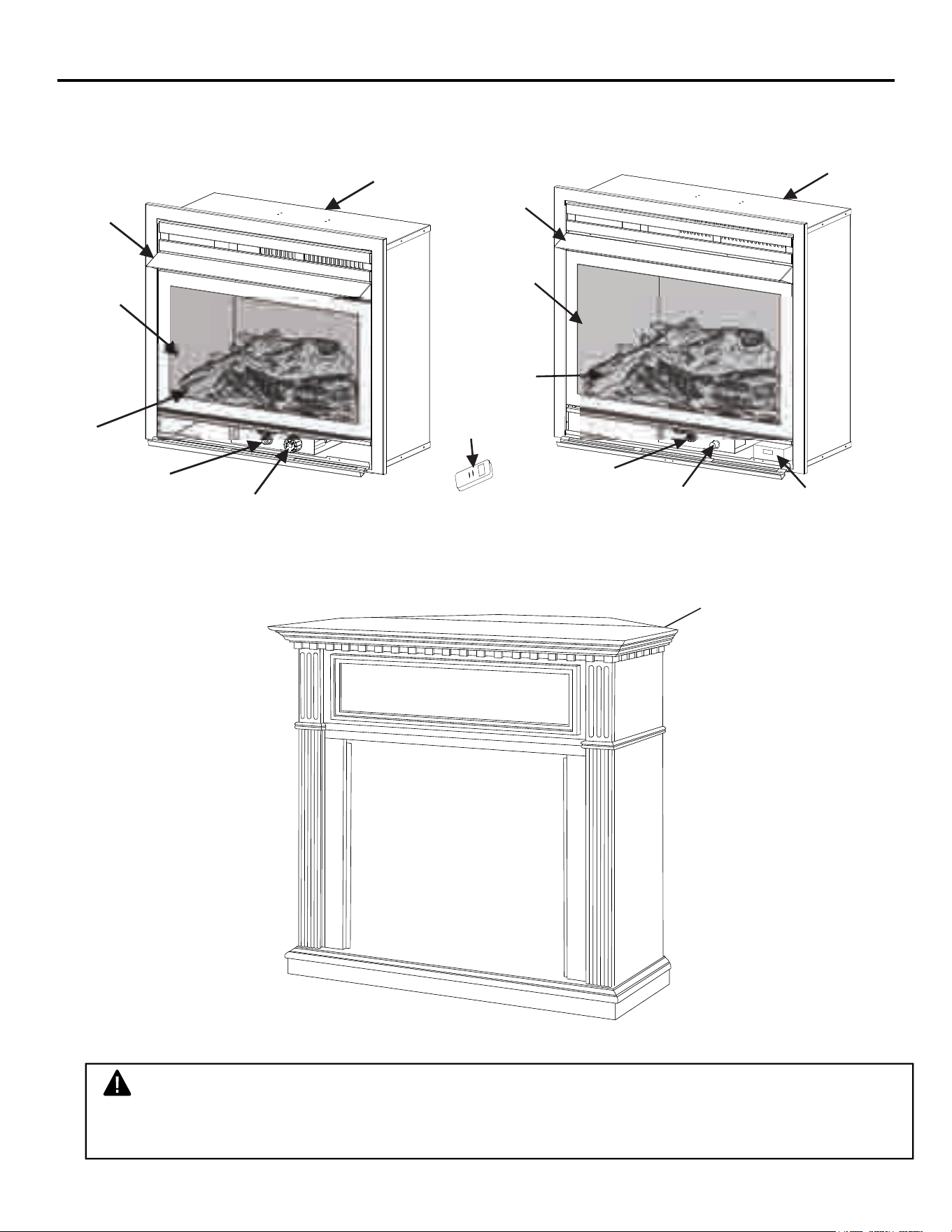
HOOD ASSEMBLY (IF REQUIRED)
:$51,1*$OZD\VKDYHVFUHHQLQSODFHEHIRUHRSHUDWLQJ¿UHSODFH7KLVSUHYHQWV
H[FHVVLYHWHPSHUDWXUHVRQ¿UHSODFHVXUIDFHV
:$51,1*)DLOXUHWRSRVLWLRQWKHSDUWVLQDFFRUGDQFHZLWKWKHVHGLDJUDPVRUIDLOXUHWR
XVHRQO\SDUWVVSHFL¿FDOO\DSSURYHGZLWKWKLV¿UHSODFHPD\UHVXOWLQSURSHUW\GDPDJH
RUSHUVRQDOLQMXU\
Tools Required:
• Phillips screwdriver • scissors
,IHTXLSSHGOLIW¿UHSODFHVFUHHQXSDQGSXOORXWWRUHPRYH6HH)LJ6HWVFUHHQDVLGHXQWLO
installation has been completed.
&XWWZRSODVWLFVWUDSVWRUHPRYHORJIURP¿UHER[FDYLW\6HWORJDVLGH
3. An optional blower is available. See Accessories, page 38. Install optional blower now. Follow
installation instructions provided with blower.
4. Locate four black Phillips sheet metal screws in hardware packet.
6OLGHKRRGEHWZHHQORXYHUDQG¿UHER[WRSDQGDOLJQVFUHZKROHV
,QVHUWVFUHZVDVVKRZQLQ)LJXUH7LJKWHQVFUHZV¿UPO\
Fig. 2 - Removing and Installing Screen
Fig. 3 - Assembling Hood
(If Required)
Shoulder Screw
Screen
Firebox Top
Louver
Sheet Metal
Screws
Hood
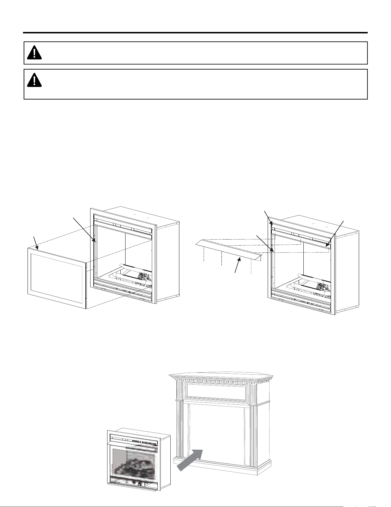
&DUHIXOO\OLIWWKHLQVHUWWKURXJKWKHFHQWHURSHQLQJLQWKHIURQWRIWKH¿UHSODFH6OLGHWKHLQVHUWEDFN
through the opening until the metal trim makes contact with the front of the mantel.

9
PREPARING FOR INSTALLATION
$,5)25&20%867,21$1'9(17,/$7,21
WARNING: This heater shall not be installed in a room or space unless the required volume
of indoor combustion air is provided by the method described in the Nation Fuel Gas Code, ANSI
Z223.1/NFPA 54, the International Fuel Gas Code, or applicable local codes.
352'8&,1*$'(48$7(9(17,/$7,21
$OOVSDFHVLQKRPHVIDOOLQWRRQHRIWKHWKUHHIROORZLQJYHQWLODWLRQFODVVL¿FDWLRQV
1. Unusually Tight Construction
8QFRQ¿QHG6SDFH
&RQ¿QHG6SDFH
The information on pages 9 through 11 will help you classify your space and provide adequate ventilation.
&RQ¿QHGDQG8QFRQ¿QHG6SDFH
$FRQ¿QHGVSDFHDVDVSDFHZKRVHYROXPHLVOHVVWKDQFXIWSHU%78KUPASHUNZ
RIWKHDJJUHJDWHLQSXWUDWLQJRIDOODSSOLDQFHVLQVWDOOHGLQWKDWVSDFHDQGDQXQFRQ¿QLQJVSDFHDVD
VSDFHZKRVHYROXPHLVQRWOHVVWKDQFXIWSHU%78KUPASHUNZRIWKHDJJUHJDWH
input rating of all appliances installed in that space. Rooms connecting directly with the space in
which the appliances are installed*, through openings not furnished with doors, are considered a
SDUWRIWKHXQFRQ¿QHGVSDFH
7KLVKHDWHUVKDOOQRWEHLQVWDOOHGLQDFRQ¿QHGVSDFHRUXQXVXDOO\WLJKWFRQVWUXFWLRQXQOHVVSURYLVLRQV
are provided for adequate combustion and ventilation air.
* Adjoining rooms are connecting only if there are doorless passageways or ventilation
grills between them.
8QXVXDOO\7LJKW&RQVWUXFWLRQ
The air that leaks around doors and windows may provide enough fresh air for combustion and venti-
lation. However, in buildings of unusually tight construction, you must provide additional
fresh air.
8QXVXDOO\WLJKWFRQVWUXFWLRQLVGH¿QHGDVFRQVWUXFWLRQZKHUH
a) walls and ceilings exposed to the outside atmosphere have a continuous water vapor retarder
with a rating of one perm (6x10-11kg per pa-sec-m2) or less with openings gasketed or sealed
and
b) weather stripping has been added on windows that can be opened and on doors and
c) caulking or sealants are applied to areas such as joints around window and door frames,
EHWZHHQVROHSODWHVDQGÀRRUVEHWZHHQZDOOFHLOLQJMRLQWVEHWZHHQZDOOSDQHOVDW
penetrations for plumbing, electrical, and gas lines, and at other openings.
If your home meets all of the three criteria above, you must provide additional fresh air.
See “Ventilation Air From Outdoors” (page 10). If your home does not meet all of the
three criteria above, proceed to “Determining Fresh-Air Flow For Heater Location”.

10
PREPARING FOR INSTALLATION
'(7(50,1,1*)5(6+$,5)/2:)25+($7(5/2&$7,21
'HWHUPLQLQJLI<RX+DYHD&RQ¿QHGRU8QFRQ¿QHG6SDFH
8VHWKLVZRUNVKHHWWRGHWHUPLQHLI\RXKDYHDFRQ¿QHGRUXQFRQ¿QHGVSDFH
6SDFH Includes the room in which you will install heater plus any adjoining rooms with
doorless passageways or ventilation grills between the rooms.
1. Determine the volume of the space Length × Width × Height = cu. ft. (volume of space)
Example: Space size 20 ft. (length) × 16 ft.(width) × 8 ft. (ceiling height) = 2560 cu. ft. (volume
of space)
If additional ventilation to adjoining room is supplied with grills or openings, add the volume of these
rooms to the total volume of the space.
2. Divide the space volume by 50 cu. ft. to determine the maximum BTU/hr the space can support.
_______ (volume of space) ÷ 50 cu. ft.= (Maximum BTU/hr the space can support)
Example: 2560 cu. ft. (volume of space) ÷ 50 cu. ft. = 51.2 or 51,200 (maximum BTU/hr the space
can support)
3. Add the BTU/hr of all fuel burning appliances in the space.
Vent-free heater _________ BTU/hr
Gas water heater* ________BTU/hr
Gas furnace _____________BTU/hr
Vented gas heater ________BTU/hr Example:
Gas heater logs __________BTU/hr Gas water heater 30,000 BTU/hr
Other gas appliances*+ ____BTU/hr Vent-free heater + 26,000 BTU/hr
Total = ____BTU/hr Total = 56,000 BTU/hr
*Do not include direct-vent gas appliances. Direct-vent draws combustion air from the
outdoors and vents to the outdoors.
4. Compare the maximum BTU/hr the space can support with the actual amount of BTU/hr used.
_______ BTU/hr (maximum the space can support)
_______ BTU/hr (actual amount of BTU/hr used).
Example : 51,200 BTU/hr (maximum the space can support) 56,000 BTU/hr (actual amount of
BTU/hr used)
7KHVSDFHLQWKHDERYHH[DPSOHLVDFRQ¿QHGVSDFHEHFDXVHWKHDFWXDO%78KUXVHGLVPRUHWKDQ
the maximum BTU/hr the space can support.
You must provide additional fresh air. Your options are as follows:
a) Rework worksheet, adding the space of an adjoining room. If the extra space provides an
XQFRQ¿QHGVSDFHUHPRYHGRRUWRDGMRLQLQJURRPRUDGGYHQWLODWLRQJULOOVEHWZHHQURRPV6HH
“Ventilation Air From Inside Building,” page 11.
b) Vent room directly to the outdoors. See “Ventilation Air From Outdoors”, page 11.
F,QVWDOODORZHU%78KUKHDWHULIORZHU%78KUVL]HPDNHVURRPXQFRQ¿QHG,IWKHDFWXDO%78KU
XVHGLVOHVVWKDQWKHPD[LPXP%78KUWKHVSDFHFDQVXSSRUWWKHVSDFHLVDQXQFRQ¿QHGVSDFH
You will need no additional fresh air ventilation.
11
PREPARING FOR INSTALLATION
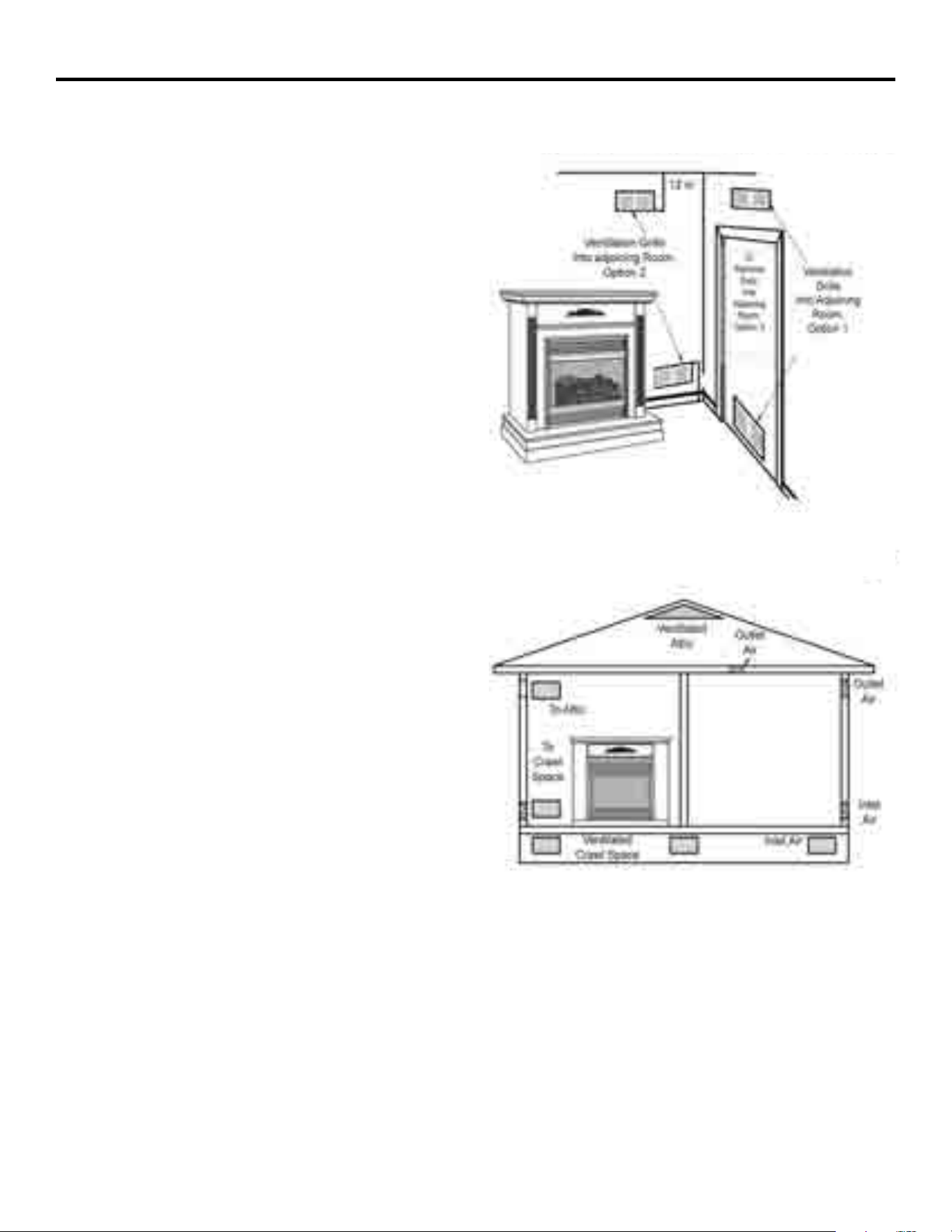
9HQWLODWLRQ$LU)URP,QVLGH%XLOGLQJ
This fresh air would come from adjoining
XQFRQ¿QHGVSDFH:KHQYHQWLODWLQJWRDQ
DGMRLQLQJXQFRQ¿QHGVSDFH\RXPXVW
provide two permanent openings: one
within 12 in. of the wall connecting
the two spaces (see options 1 and 2,
Fig. 4). You can also remove door into
adjoining room (see option 3, Fig. 4).
Follow the National Fuel Gas Code
NFPA 54/ANS Z223.1. Air for Combustion
and Ventilation for required size of
ventilation grills or ducts.
9HQWLODWLRQ$LU)URP2XWGRRUV
Provide extra fresh air by using ventilation
grills or duct. You must provide two
permanent openings: one within 12 in. of
WKHFHLOLQJDQGRQHZLWKLQLQRIWKHÀRRU
Connect these items directly to the outdoors
or spaces open to the outdoors. These
spaces include attics and crawl spaces.
Follow the National Fuel Gas Code NFPA
54/ANS Z223.1. Air for Combustion and
Ventilation for required size of ventilation
grills or ducts.
IMPORTANT: Do not provide openings for
inlet or outlet air into attic if attic has a
thermostat-controlled power vent. Heated
air entering the attic will activate the power
vent. Rework worksheet, adding the space
RIWKHDGMRLQLQJXQFRQ¿QHGVSDFH7KH
combined spaces must have enough fresh
air to supply all appliances in both spaces.
Fig. 4 - Ventilation Air from
Inside Building
Fig. 5 - Ventilation Air from Outdoors

12
INSTALLATION
NOTICE: This heater is intended for use as supplemental heat. Use this heater along with your
primary heating system. Do not install this heater as your primary heat source. If you have a
central heating system, you may run system’s circulating blower while using heater. This will
help circulate the heat throughout the house.
WARNING:$TXDOL¿HGWHFKQLFLDQPXVWLQVWDOOKHDWHU)ROORZDOOORFDOFRGHV
WARNING: Never install the heater:
• in a bedroom or bathroom
• in a recreational vehicle
ZKHUHFXUWDLQVIXUQLWXUHFORWKLQJRURWKHUÀDPPDEOHREMHFWVDUHOHVVWKDQ
in. from the front, top or sides of the heater.
LQKLJKWUDႈFDUHDV
• in windy or drafty areas
WARNING: Maintain the minimum clearances. If possible, provide greater clearances from the
ÀRRUFHLOLQJDQGDGMRLQLQJZDOOWKDQUHTXLUHG
CAUTION: This heater creates warm air currents. These currents move heat to wall surfaces next
to heater. Installing heater next to vinyl or cloth wall coverings or operating heater where impurities
VXFKDVWREDFFRVPRNHDURPDWLFFDQGOHVFOHDQLQJÀXLGVRLORUNHURVHQHODPSVHWFLQWKHDLU
exist, may cause walls to discolor.
IMPORTANT: 9HQWIUHHKHDWHUVDGGPRLVWXUHWRWKHDLU$OWKRXJKWKLVLVEHQH¿FLDOLQVWDOOLQJKHDWHULQ
rooms without enough ventilation air may cause mildew to form from too much moisture. See Air for
Combustion and Ventilation, pages 9 through 11.
CHECK GAS TYPE
Be sure your gas supply is right for your heater.
CLEARANCES TO COMBUSTIBLES
Carefully follow the instructions below. This heater is a designed to sit directly on the mantel base.
IMPORTANT: Maintain the minimum clearances shown in Figure 6 on page 12. If you can, provide
JUHDWHUFOHDUDQFHVIURPÀRRUFHLOLQJDQGMRLQLQJZDOO
13
INSTALLATION
FIREPLACE CLEARANCES
&$87,21,I\RXLQVWDOOWKH¿UHSODFHLQDKRPHJDUDJH
¿UHSODFHSLORWDQGEXUQHUPXVWEHDWOHDVWDERYHÀRRU
ORFDWH¿UHSODFHZKHUHPRYLQJYHKLFOHZLOOQRWKLWLW
)RUFRQYHQLHQFHDQGHႈFLHQF\LQVWDOO¿UHSODFH
• where there is easy access for operation, inspection and service
• in coldest part of room
• If this appliance is to be installed directly on carpeting, tile or other combsutible material, other than
ZRRGÀRRULQJWKHDSSOLDQFHPXVWEHLQVWDOOHGRQDPHWDORUZRRGSDQHOH[WHQGLQJWKHIXOOZLGWKDQG
depth of the appliance.
An optional blower kit is available from your retailer. See Accessories, page 38. If planning to use
blower, follow instructions provided with blower for power source.
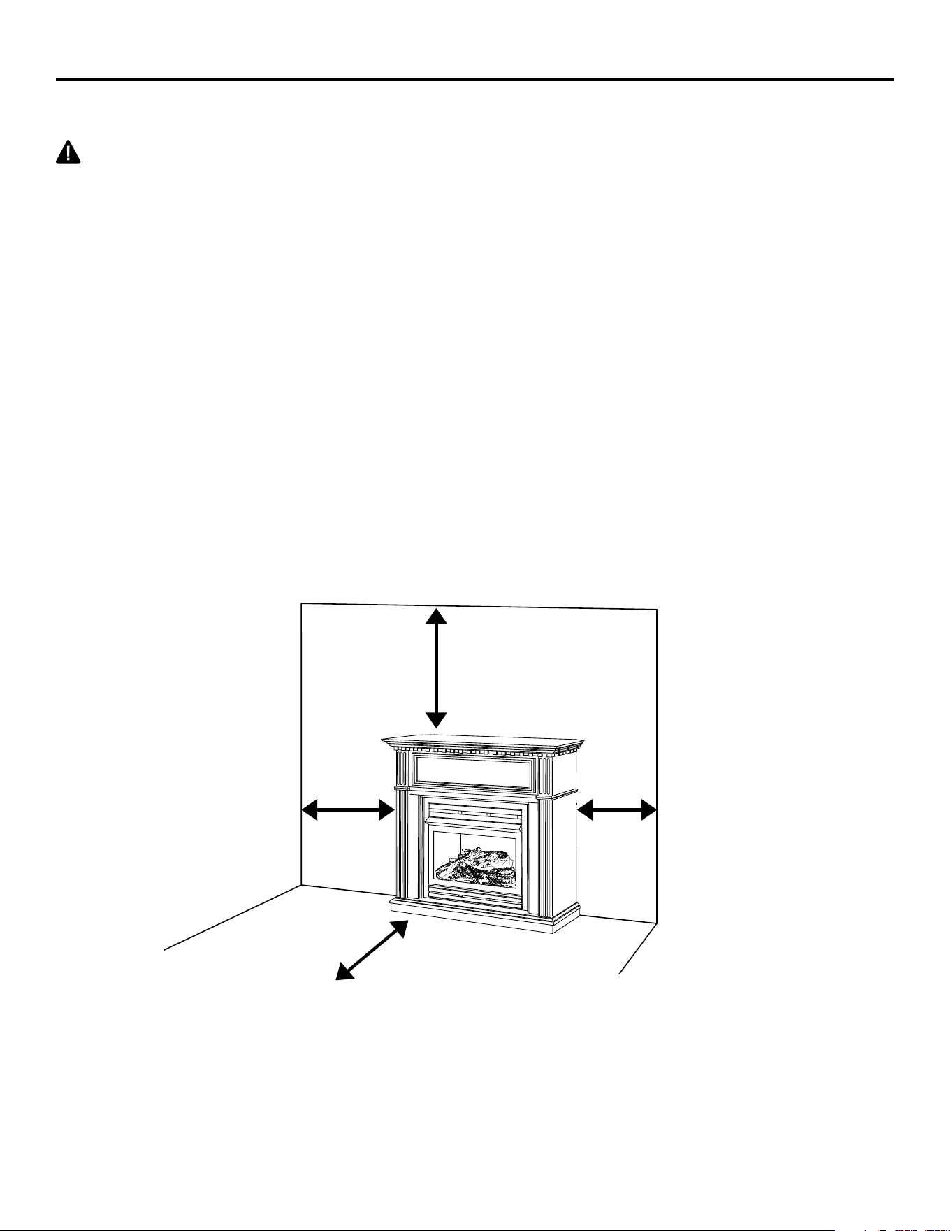
0LQLPXP&OHDUDQFHV)RU6LGH&RPEXVWLEOH0DWHULDO6LGH:DOODQG&HLOLQJ
$&OHDUDQFHVIURPWKHVLGHRIWKH¿UHSODFHFDELQHWWRDQ\FRPEXVWLEOHPDWHULDODQGZDOOVKRXOG
follow diagram in Figure 6.
%&OHDUDQFHVIURPWKHWRSRIWKH¿UHSODFHRSHQLQJWRWKHFHLOLQJVKRXOGQRWEHOHVVWKDQ
6’’
Either
Side
Min.
36’’
Fig. 6 - Minimum Clearance to
Combustible Material
Min.
36''
36''
6''
Either
Side
6''
7KLV¿UHER[LVRQO\IRUXVHZLWKWKHPDQWHOSURYLGHG
14
INSTALLATION
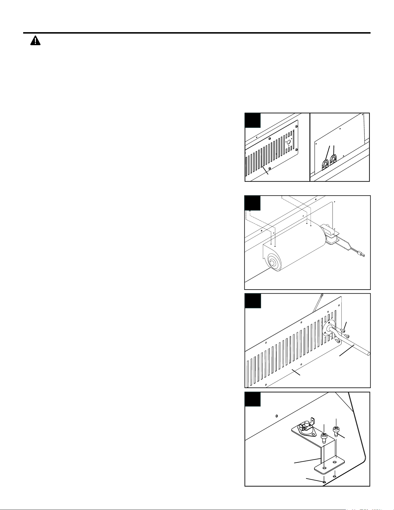
1. Remove Blower Top Access Panel
and Bottom Panel.
FF
2. Mount Blower (B) onto bottom of
Fireplace Top using 4 screws (F).
3. Pre-thread the Power Cord
Screws (3). Attach Power Cord (A)
to Blower Access Panel.
4. Attach Temperature Sensor (C) to
the Combustion Top using 2 sheet
metal screws.
2
3
Access Panel
Regulator
Screws
Power Cord
Access Panel
WARNING: This optional blower is equipped with a three-prong (grounding) plug for
your protection against shock hazard and must be plugged directly into a properly
grounded three-prong receptacle.
Firebox must be disconnected from gas supply and removed from mantel before
LQVWDOOLQJIDQDFFHVVRU\&RQWDFWDTXDOL¿HGVHUYLFHSHUVRQWRGRWKLV
%/2:(5,167$//$7,21237,21$/
4
Sheet
Metal
Screws
Senser
Bracket
Combustion Top
Mounting Holes
C
1
15
INSTALLATION
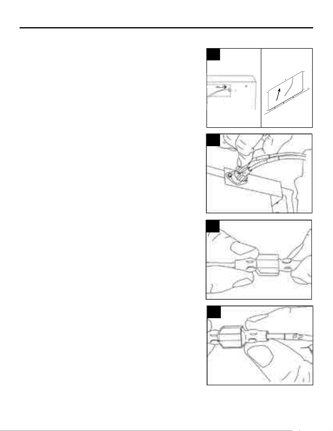
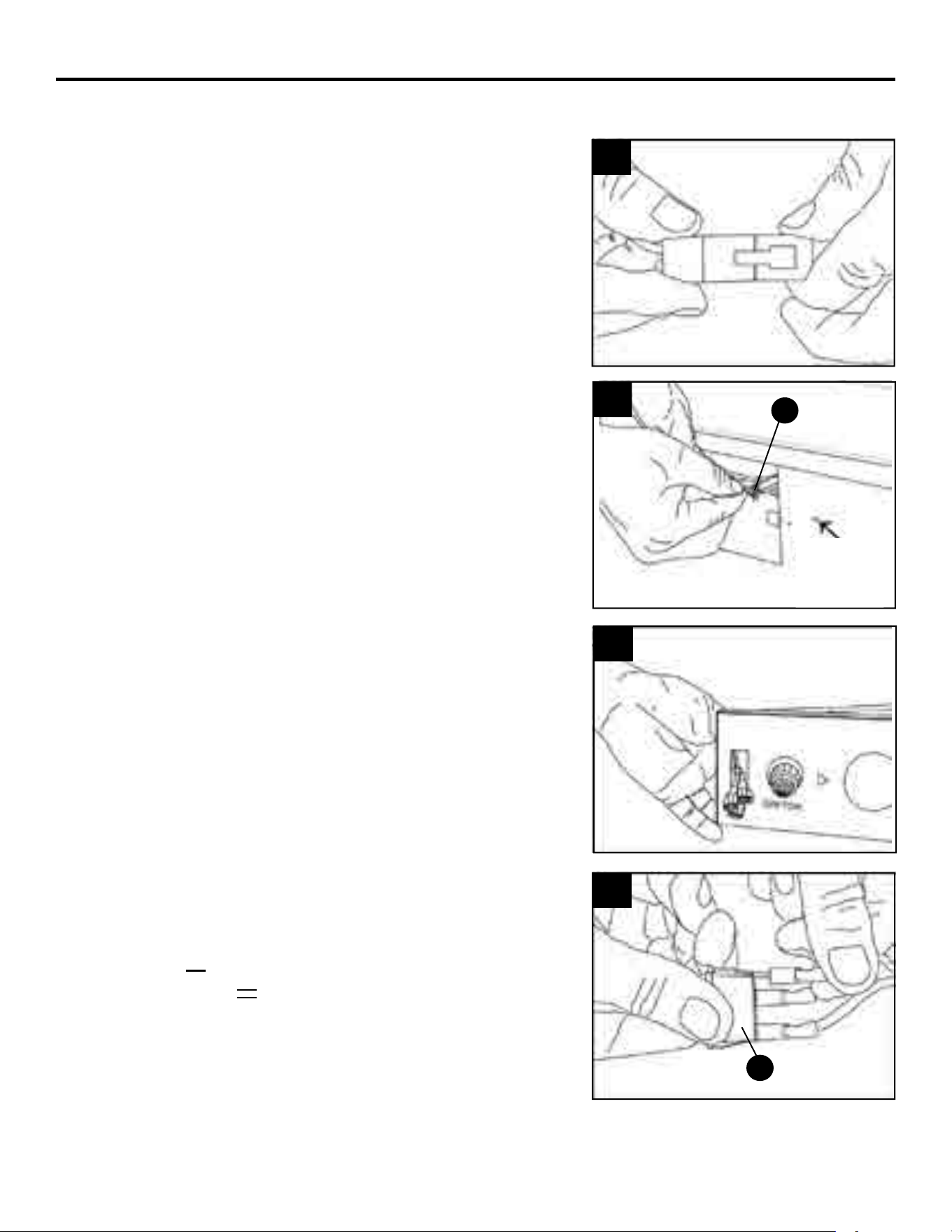
5. Important: Insert the wires marked
with AUTO, OFF and MAN into line
slot on the right corner. Keep wires
close to the bottom and guide to
the front using the bottom access.
6. Insert two wires’ female plugs
marked with T1 and T2 (black and
yellow) into two male ports on
Temperature Sensor.
7. Insert the female plug on the white
power supply wire (marked with
P1), into the corresponding male
port (marked with P1).
6
7
8. Insert the female plug (marked
with P2) into the corresponding
male port, which is on the black
power supply wire (marked
with P2).
8
5
234
16
INSTALLATION
9. Insert the blower link (male plug)
into the power link (female port).
9
10. ,PSRUWDQW: Bind wires with cable
tie (G), and attach cable tie (G)
LQWRWKH¿[HGKROHIURPWKHLQ
side of the Outer Casing. Do
the same with the wires through
the bottom access panel. Keep
wires from obstructing the blower.
10
11. Insert AUTO, OFF, MAN wires
through the Rocker Switch
opening.
11
12
)L[HG
Hole
G
E
12. Connect AUTO, OFF, MAN wires
to the three corresponding male
ports on the Rocker Switch (E).
Match the "Auto" wire to the
symbol " " and the "Man" wire
to the symbol " " on the rocker
switch (E).
17
INSTALLATION
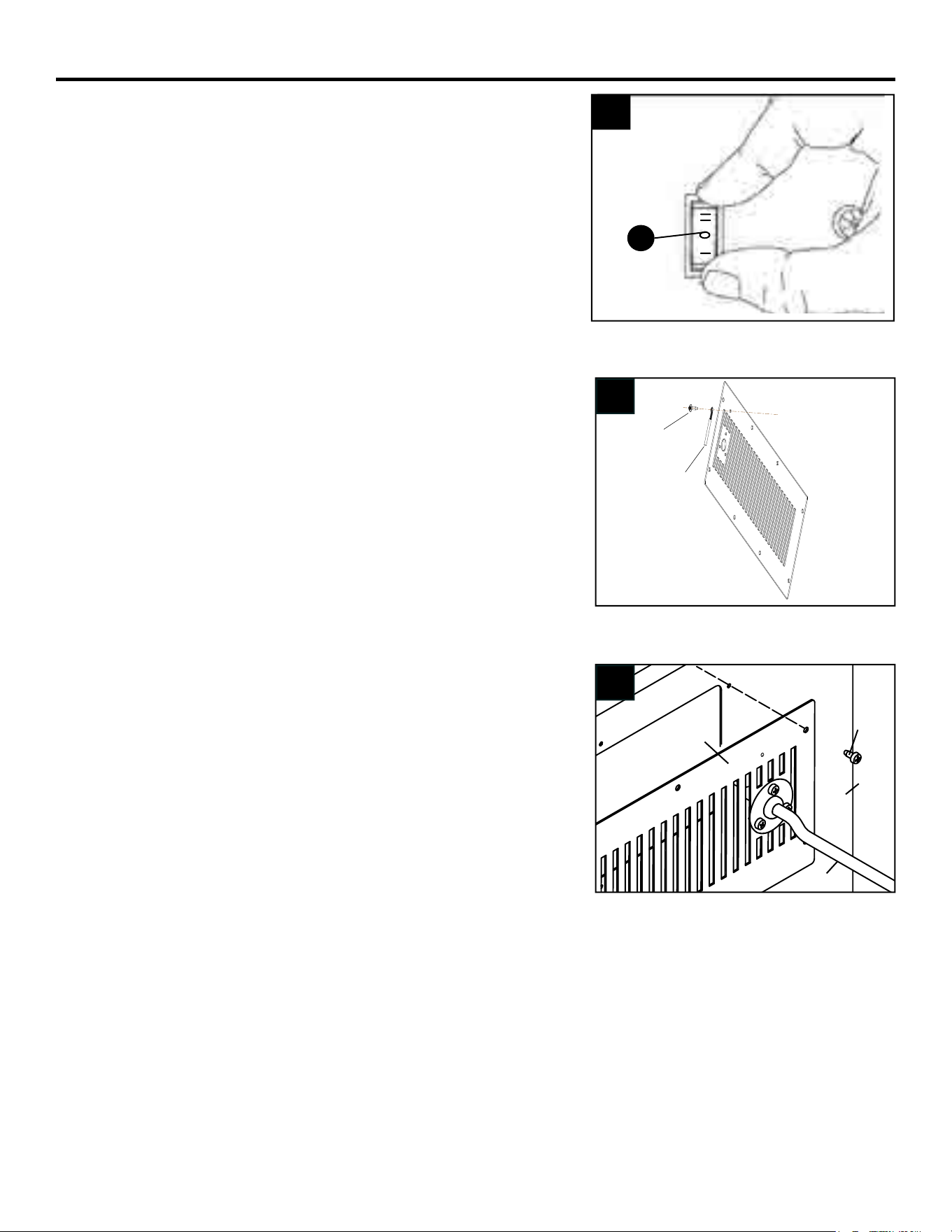
13. Push Rocker Switch (E) into
Control Panel and secure.
13
15. Check that all wires are secure
and reattach Blower Access Panel
to Outer Casing.
14. Secure the Green Ground wire to
the Grounding screw hole from
the inside with the screw.
E
1
1
2
2
3
3
4
4
A A
B B
C C
D D
SHEET 1 OF 1
DRAWN
CHECKED
QA
MFG
APPROVED
dandowning
4/12/2013
DWG NO
Power Cord Attachment
TITLE
SIZE
C
SCALE
REV
Green Ground
Wire
15
14
Screw
Outer
Casing
Access Panel
Power Cord
Screw
18
INSTALLATION
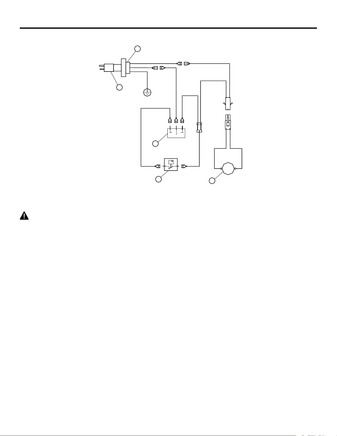
t
WHITE
GREEN
RED
BLACK
BLACK
AUTO OFF
MAN
1
2
3
4
5
~120V
60Hz
1. Power Cord
2. Bushing Strain Relief
3. Blower
4. Temperature Sensor
5. Rocker Switch
FAN
Electrical Wiring Diagram
CAUTION: Label all wires prior to disconnection when servicing controls. Wiring errors can
cause improper and dangerous operation.
Verify proper operation after servicing.
NOTE: If any of the original wire as supplied with the appliance must be replaced, it must be
replaced with a wire of at least an equal temperature rating.
19
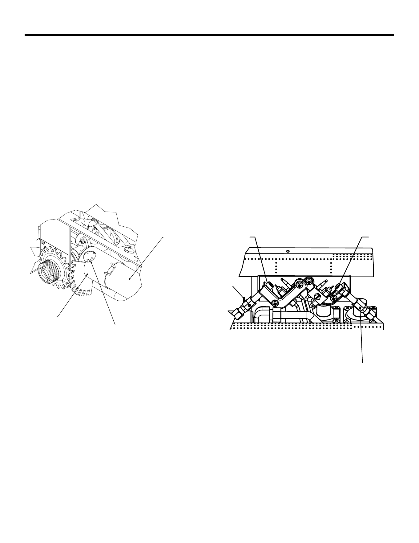
GAS SELECTION INSTRUCTIONS
CAUTION: The knob to the gas selection means shall not be accessed or adjusted while the appli-
ance is in operation.
CAUTION: Two gas line installations at the same time are prohibited. The access plate to simple
switching means shall not be opened while heater is in operation.
,QVWDOODWLRQDQGDGMXVWPHQWVVKDOOEHPDGHE\DTXDOL¿HGWHFKQLFLDQRQO\
NOTE: If you are connecting this appliance to propane do not make any adjustments. Proceed to
installing the gas line as instructed in the Owner’s Manual.
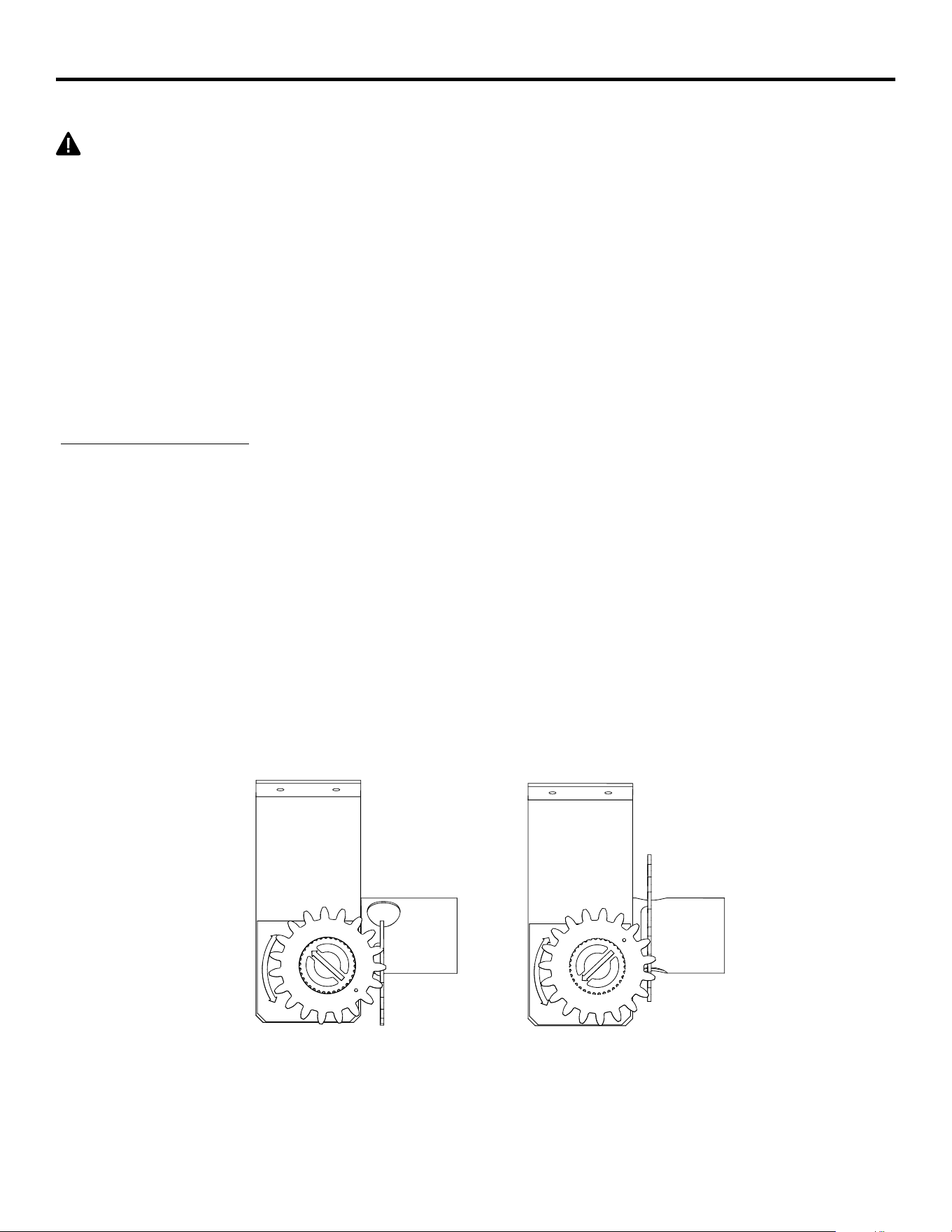
Convert to natural gas:
Step 1 - Adjust the gas selector valve
Push in on the selector valve Knob and rotate the knob
counter-clockwise until it stops. Release the knob (See Fig. 8)
'RQRWRSHUDWHWKHDSSOLDQFHEHWZHHQORFNHGSRVLWLRQV
Reverse step 1 to convert back to propane gas.
INSTALLATION
WARNING: This appliance can be used with propane or natural gas. It is shipped from the
factory adjusted for use with propane.
LP
NG
LP
NG
Fig. 8 - Selector Valve
Propane
Position
Natural Gas
Position
20
CONNECTING TO GAS SUPPLY
WARNING$TXDOL¿HGVHUYLFHWHFKQLFLDQPXVWFRQQHFWKHDWHUWRJDVVXSSO\)ROORZDOOORFDO
codes.
CAUTION: Never connect heater directly to the gas supply. This heater requires an external
regulator (not supplied). The external regulator between the gas supply and heater must be installed.
Gas supplier provides external regulator for natural gas.
WARNING: Never connect heater to private (non-utility) gas wells. This gas is commonly known
as wellhead gas.
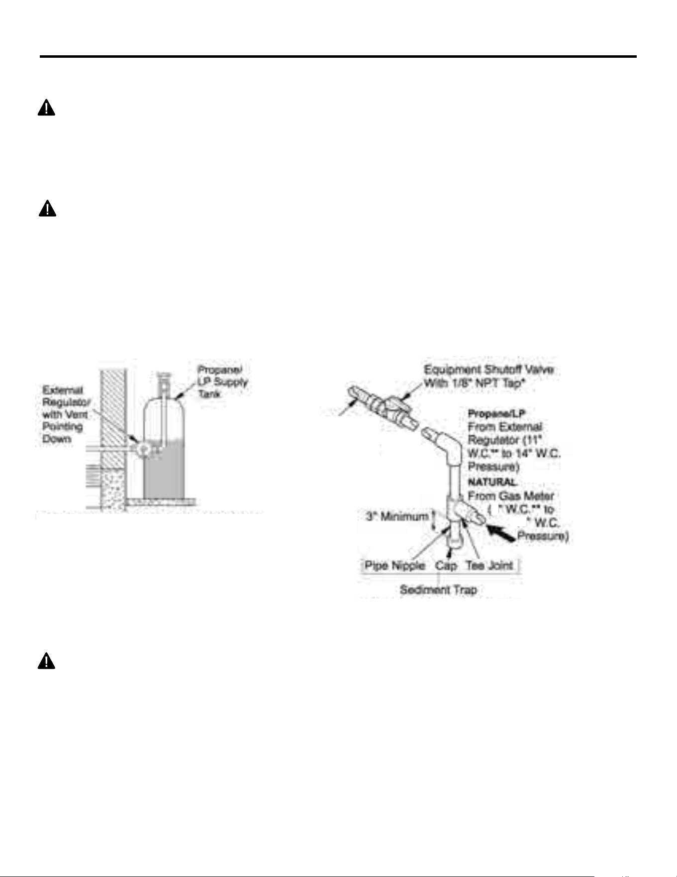
The installer must supply an external regulator for liquid propane. The external regulator is
provided by the gas supplier for natural gas. The external regulator will reduce incoming gas pres-
sure. You must reduce incoming gas pressure to between 11 and 14 in. of water column for propane
and between 6 and 14 in. of water column for natural gas. If you do not reduce incoming gas pres-
sure, heater regulator damage could occur. Install external regulator with the vent pointing down as
shown in Fig. 6. Pointing the vent down protects it from freezing rain or sleet.
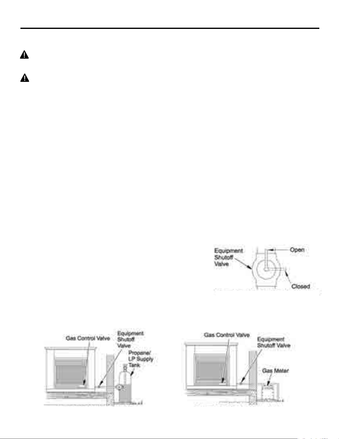
3XUFKDVHWKHRSWLRQDOHTXLSPHQWVKXWRႇYDOYHIURP\RXUORFDO+RPH&HQWHUVWRUH
INSTALLATION
CAUTION: Use only new black iron or steel pipe. Internally tinned copper tubing
may be used in certain areas. Check your local codes. Use pipe of ½ in. diameter
or greater to allow proper volume gas to heater. If pipe is too small, loss of pressure
ZLOORFFXU,QVWDOODWLRQPXVWLQFOXGHDQHTXLSPHQWVKXWRႇYDOYHXQLRQDQGSOXJJHG
1/8-in. NPT tap. Locate NPT tap within reach for test gauge hook up. NPT tap must
be upstream from heater (See Fig. 10).
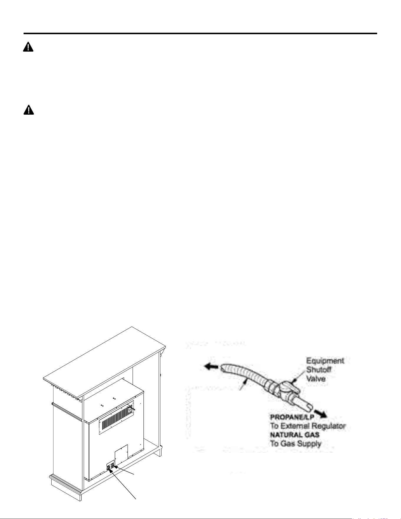
IMPORTANT,QVWDOOHTXLSPHQWVKXWRႇYDOYHLQDQDFFHVVLEOHORFDWLRQ7KHHTXLSPHQW
VKXWRႇYDOYHLVIRUWXUQLQJRQRUVKXWWLQJRႇWKHJDVWRWKHDSSOLDQFH$SSO\SLSHMRLQW
sealant lightly to male threads. This will prevent excess sealant from going into pipe.
Excess sealant in pipe could result in clogged heater valves.
Approved
Flexible
Gas Line
or 1/2''
Black Pipe
Fig. 9 - Regulator Conversion
Fig. 10 - Gas Connection
6
14
21
LP Regulator
NG Regulator
INSTALLATION
,QVWDOODWLRQ,WHPV1HHGHG1RW3URYLGHG
Fig. 11 - Attaching Flexible Gas Line
WR(TXLSPHQW6KXWR௺9DOYH
Flexible Gas Line
or Black Pipe to
Fireplace Cabinet
Regulator
To Regulator
• 8'' Adjustable Wrench
• 8'' Pipe Wrench
• Flexible Gas Line (24'' Min.) or 1/2'' Black Pipe
• 90 Deg. 3/8 NPT x 3/8'' Flare Fitting or 3/8'' Street Elbow
• Sealant (Resistant to Propane (LP) Gas)
6KXW2ႇ9DOYH
1) A variety of options are possible for routing the Gas Connection Lines depending on where
your Gas Supply line is located. Install the 3/8'' Fitting to the Fireplace Cabinet Regulator
using Sealant and direct the attachment and either left or right toward the Gas Supply Line.
,QVWDOOWKH*DV/LQHWRWKH'HJ¿WWLQJDQGDWWDFKWRWKH6KXW2ႇ9DOYH,WPD\EH
necessary to cut and access hole in the side or bottom of the Mantel Cabinet depending on
your particular connection.
3) Check all connections for gas leaks.
NOTICE: Most building codes do not permit concealed gas connections. Check
your local building code prior to using a Flexible Gas Line for this installation.
CAUTION: Use pipe joint sealant that is resistant to gas (PROPANE or NG). We
recommend that you install a sediment trap in a supply line as shown in Fig. 10.
Locate sediment trap where it is within reach for cleaning and not likely to freeze.
Install in the piping system between fuel supply and heater. A sediment trap traps
moisture and contaminants. This keeps them from going into heater controls. If
sediment trap is not installed or is installed incorrectly, heater may not run properly.
CAUTION: Avoid damage to regulator. Hold gas regulator with wrench when
FRQQHFWLQJLQWRJDVSLSLQJDQGRU¿WWLQJV1*0RGHOVLQWRLQ:&*DV
supplier provides external regulator for natural gas.
22
9))3+''%'7,0'+9))3+''%'&&3'7
WARNING:
Failure to position the parts in accordance with these diagrams or failure to use only parts
VSHFL¿FDOO\DSSURYHGZLWKWKLVKHDWHUPD\UHVXOWLQSURSHUW\GDPDJHRUSHUVRQDOLQMXU\
CAUTION:$IWHULQVWDOODWLRQDQGSHULGLFDOO\WKHUHDIWHUFKHFNWRHQVXUHWKDWQR\HOORZÀDPHFRPHVLQ
FRQWDFWZLWKDQ\ORJ:LWKWKHKHDWHUVHWWR+LJKFKHFNWRVHHLI\HOORZÀDPHVFRQWDFWDQ\ORJ,IVR
UHSRVLWLRQORJVDFFRUGLQJWRWKHORJLQVWDOODWLRQLQVWUXFWLRQVLQWKLVPDQXDO<HOORZÀDPHVFRQWDFWLQJ
logs will create soot.
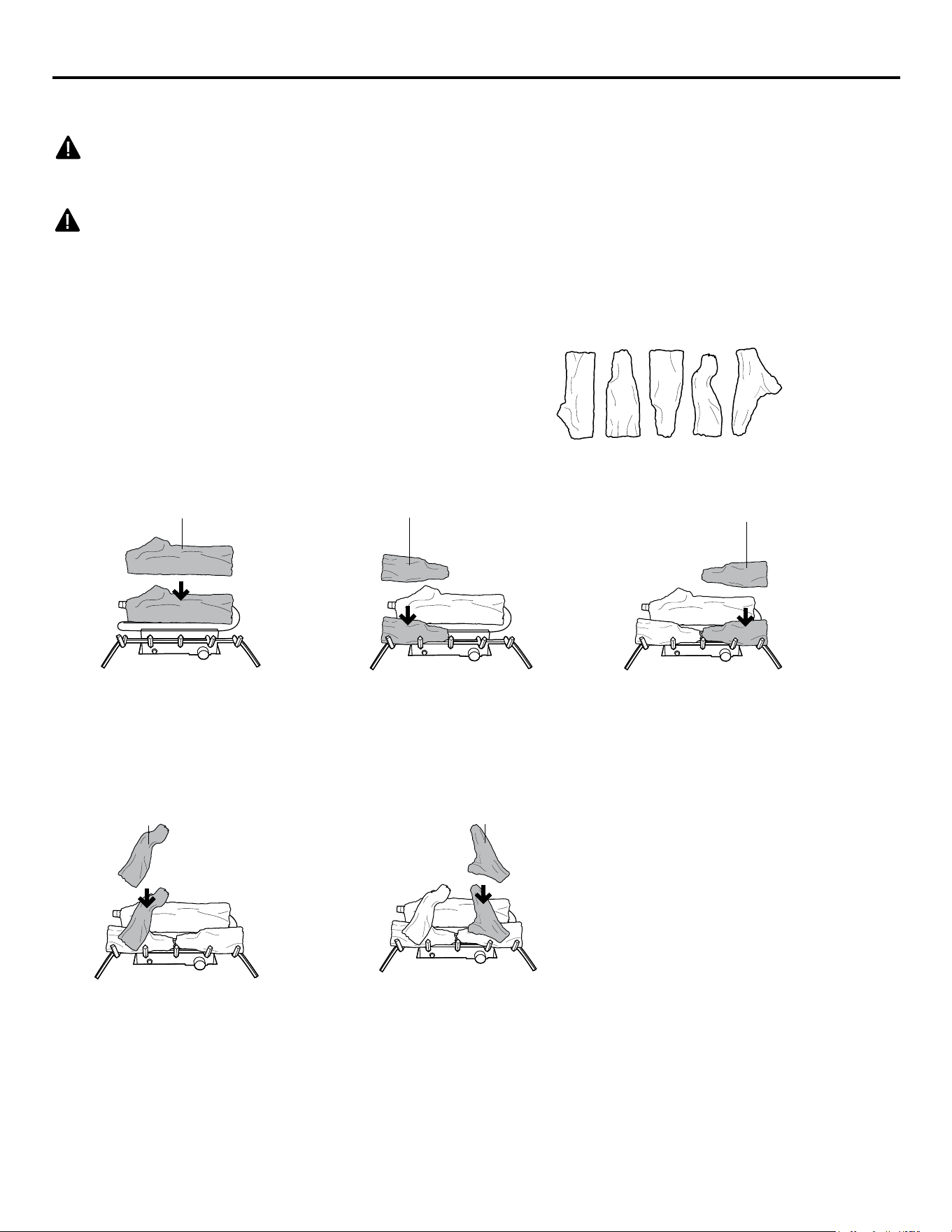
It is very important to install the logs
exactly as instructed. Do not modify logs.
Use only logs supplied with heater.
Each log is marked with a number.
this number will help you identify the logs
when installing.
Provided Logs: 5
Installing Log #1 Installing Log #2 Installing Log #3
2
1
3
1. Insert log #1 onto the
rear row of pins on the
base pan.
2. Insert log #2 onto the
front left pin on the base
pan.
3. Insert log #3 onto the
front right pin on the base
pan.
Installing Log #4 Installing Log #5
4
5
4. Insert log #4 onto the left
pin of log #1 and the pin of
log #2.
5. Insert log #5 onto the
right pin of log #1 and the
pin of log #3.
1
2 34 5
ASSEMBLING LOGS
23
9))3+'5'5%'5+)6'5&
WARNING:
Failure to position the parts in accordance with these diagrams or failure to use only parts
VSHFL¿FDOO\DSSURYHGZLWKWKLVKHDWHUPD\UHVXOWLQSURSHUW\GDPDJHRUSHUVRQDOLQMXU\
CAUTION:$IWHULQVWDOODWLRQDQGSHULGLFDOO\WKHUHDIWHUFKHFNWRHQVXUHWKDWQR\HOORZÀDPHFRPHVLQ
FRQWDFWZLWKDQ\ORJ:LWKWKHKHDWHUVHWWR+LJKFKHFNWRVHHLI\HOORZÀDPHVFRQWDFWDQ\ORJ,IVR
UHSRVLWLRQORJVDFFRUGLQJWRWKHORJLQVWDOODWLRQLQVWUXFWLRQVLQWKLVPDQXDO<HOORZÀDPHVFRQWDFWLQJ
logs will create soot.
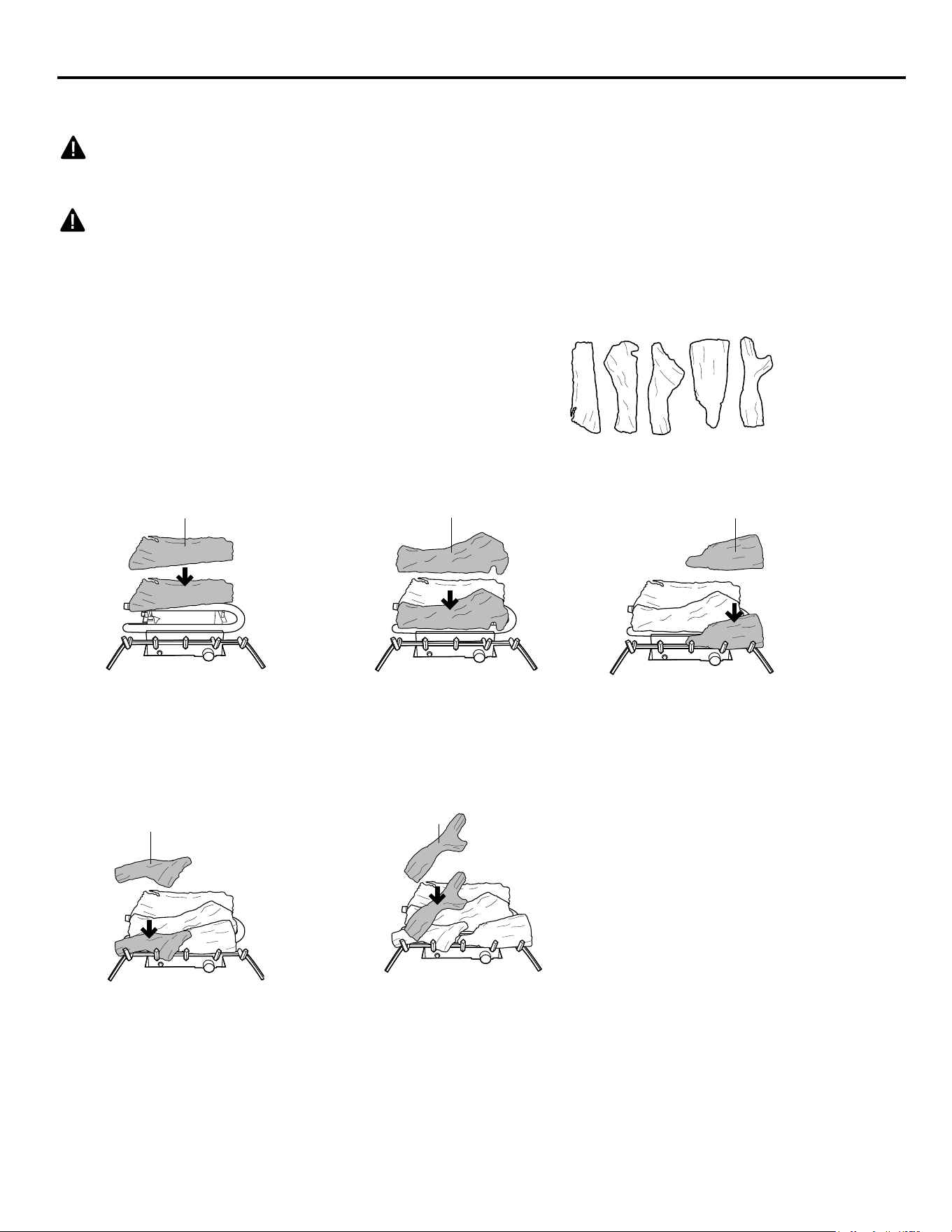
It is very important to install the logs
exactly as instructed. Do not modify logs.
Use only logs supplied with heater.
Each log is marked with a number.
this number will hep you identify the logs
when installing. After installing logs, add
decorative cinders around the grate base,
do not place any decorative cinders on
logs or burner.
Provided Logs: 5
Installing Log #1 Installing Log #2 Installing Log #3
2
1
4
1. Insert log #1 onto the
rear brackets of the base
pan.
2. Insert log #2 onto the
middle row of pins on the
base pan.
4 . Insert log #4 onto the
front left pin of the base
pan.
Installing Log #4 Installing Log #5
3
5
3. Insert log #3 onto the
front right pin of the base
pan.
5. Insert log #5 onto the
left pins of log #1 & #2 and
the pin of log #3.
ASSEMBLING LOGS
5
4123
24
INSTALLATION
CHECKING GAS CONNECTIONS
WARNING: Test all gas piping and connections for leaks after installing or servicing. Correct all
leaks immediately.
WARNING:1HYHUXVHDQRSHQÀDPHWRFKHFNIRUDOHDN$SSO\DPL[WXUHRIOLTXLGVRDSDQGZDWHU
to all joints. If bubbles form, there may be a leak. Correct all leaks immediately.
3UHVVXUH7HVWLQJ*DV6XSSO\3LSLQJ6\VWHP
7HVW3UHVVXUHV,Q([FHVV2I36,*N3D
'LVFRQQHFWKHDWHUZLWKLWVDSSOLDQFHPDLQJDVYDOYHFRQWUROYDOYHDQGHTXLSPHQWVKXWRႇYDOYH
from gas supply piping system. Pressures in excess of 1/2 PSIG will damage heater regulator.
&DSRႇRSHQHQGRIJDVSLSHZKHUHHTXLSPHQWVKXWRႇYDOYHZDVFRQQHFWHG
3. Pressurize supply piping system by either using compressed air or opening gas supply tank valve.
4. Check all joints of gas supply piping system. Apply mixture of liquid soap and water to gas joints. If
bubbles form, there may be a leak.
5. Correct all leaks immediately.
5HFRQQHFWKHDWHUDQGHTXLSPHQWVKXWRႇYDOYHWRJDVVXSSO\&KHFNUHFRQQHFWHG¿WWLQJVIRUOHDNV
7HVW3UHVVXUHV(TXDO7RRU/HVV7KDQ36,*N3D
&ORVHHTXLSPHQWVKXWRႇYDOYH6HH)LJ
2. Pressure supply piping system by either using compressed air or opening gas supply tank valve.
&KHFNDOOMRLQWVIURPJDVPHWHUWRHTXLSPHQWVKXWRႇYDOYH6HH)LJ$SSO\PL[WXUHRIOLTXLG
soap and water to gas joints. If bubbles form, there may be a leak.
4. Correct all leaks immediately.
3UHVVXUH7HVWLQJ+HDWHU*DV&RQQHFWLRQV
2SHQHTXLSPHQWVKXWRႇYDOYH6HH)LJ
2. Open gas supply tank valve.
3. Make sure control knob of heater is in the OFF position.
&KHFNDOOMRLQWVIURPHTXLSPHQWVKXWRႇYDOYHWRFRQWUROYDOYH
(See Fig. 13). Apply mixture of liquid soap and water to gas joints.
If bubbles form, there may be a leak.
5. Light heater (see Operation, page 23).
Check all other internal joints for leaks.
7XUQRႇKHDWHUVHH7R7XUQ2ႇ*DVWR$SSOLDQFHSDJH
Fig. 13 - Checking Gas Joints
(Propane/LP Only)
)LJ(TXLSPHQW6KXWR௺9DOYH
Fig. 14 - Checking Gas Joints
(Natural Gas Only)
25
OPERATION
FOR YOUR SAFETY
READ BEFORE LIGHTING
:$51,1*,I\RXGRQRWIROORZWKHVHLQVWUXFWLRQVH[DFWO\D¿UHRUH[SORVLRQPD\
UHVXOWFDXVLQJSURSHUW\GDPDJHSHUVRQDOLQMXU\RUORVVRIOLIH
A. This appliance has a pilot which must be lighted by the electronic ignitor. When lighting the pilot,
follow these instructions exactly.
B. BEFORE LIGHTINGVPHOODOODURXQGWKHDSSOLDQFHDUHDIRUJDV%HVXUHWRVPHOOQH[WWRWKHÀRRU
EHFDXVHVRPHJDVLVKHDYLHUWKDQDLUDQGZLOOVHWWOHRQWKHÀRRU
WHAT TO DO IF YOU SMELL GAS
• Do not try to light any appliance.
• Do not touch any electrical switch; do not use any phone in your building.
• Immediately call your gas supplier from a neighbor’s phone. Follow the gas supplier’s instructions.
,I\RXFDQQRWUHDFK\RXUJDVVXSSOLHUFDOOWKH¿UHGHSDUWPHQW
C. Use only your hand to push in or turn the gas control knob. Never use tools. If the knob will not
SXVKLQRUWXUQE\KDQGGRQ¶WWU\WRUHSDLULWFDOODTXDOL¿HGVHUYLFHWHFKQLFLDQ)RUFHGRUDWWHPSWHG
UHSDLUPD\UHVXOWLQ¿UHRUH[SORVLRQ
''RQRWXVHWKLVDSSOLDQFHLIDQ\SDUWKDVEHHQXQGHUZDWHU,PPHGLDWHO\FDOODTXDOL¿HGVHUYLFH
technician to inspect the appliance and to replace any part of the control system and any gas control
which has been under water.
LIGHTING INSTRUCTIONS
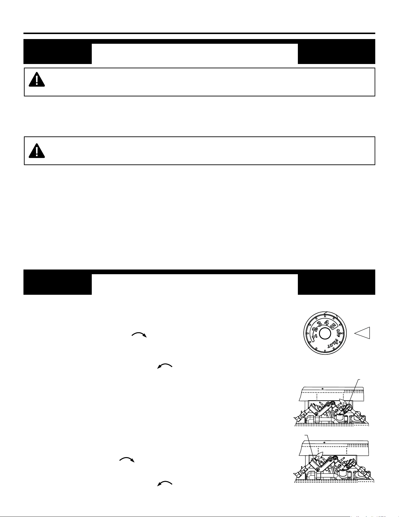
1. STOP! Read the safety information as noted above.
2SHQWKHORZHUDFFHVVSDQHOORFDWHGEHORZWKH¿UHSODFHVFUHHQ
3. Turn control knob clockwise to the “OFF” position (See Fig. 15).
:DLW¿YHPLQXWHVWRFOHDURXWDQ\JDV7KHQVPHOOIRUJDVLQFOXGLQJ
QHDUWKHÀRRU,I\RXVPHOOJDV6723)ROORZ³%´LQWKHVDIHW\LQIRUPD
tion as noted above. If you don’t smell gas, go to the next step.
5. Turn control knob counterclockwise to the “PILOT” position (See
Fig. 16). Depress control knob.
6. With control knob depressed, push down on the ignitor button until the
SLORWOLJKWV7KHSLORWLVORFDWHGEHKLQGWKH¿UHSODFHVFUHHQFHQWHUHG
near the rear of the burner.
7. Keep control knob depressed for (30) seconds after pilot lights. Release
control knob.
• If the control knob does not pop up when released, stop and immediately
FDOODTXDOL¿HGVHUYLFHWHFKQLFLDQRUJDVVXSSOLHU
• If pilot goes out repeat steps 3 through 7. Wait (1) minute before attempt-
ing to light pilot again. If after several tries the pilot still goes out, turn the
JDVFRQWURONQREFORFNZLVHWRWKH³2))´SRVLWLRQDQGFDOODTXDOL¿HG
service technician.
8. Turn control knob counterclockwise to desired setting.
9. Close lower access panel.
Fig. 15 - Control Knob
Fig. 16 - Pilot
0RGHOV9))3+''%'&&3'79))3+''%'7,0'
+
A
LP PILOT
A
NG PILOT
:$51,1*'RQRWXVHDEORZHULQVHUWKHDWH[FKDQJHULQVHUWRURWKHUDFFHVVRU\QRW
DSSURYHGIRUXVHZLWKWKLVKHDWHU
26
OPERATION
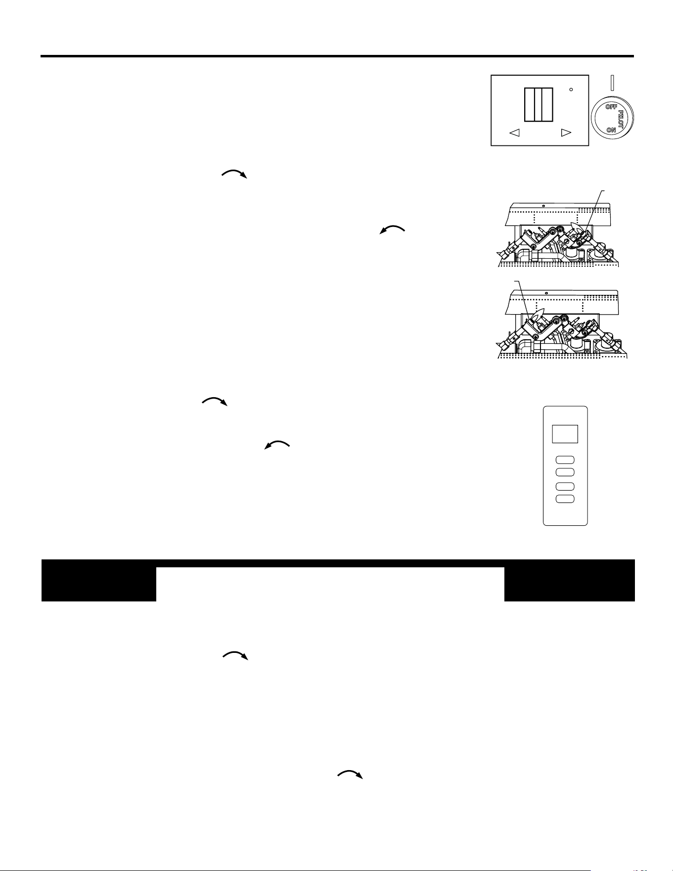
0RGHO9))3+'5'5%'5+)6'5&
1. STOP! Read the safety information on the page before this.
2SHQWKHORZHUDFFHVVSDQHOORFDWHGEHORZWKH¿UHSODFHVFUHHQ
• Set receiver switch to “ON” position (See Fig. 17).
3. Turn control knob clockwise to the “OFF” position (See Fig. 17).
:DLW¿YHPLQXWHVWRFOHDURXWDQ\JDV7KHQVPHOOIRUJDVLQFOXGLQJ
QHDUWKHÀRRU,I\RXVPHOOJDV6723)ROORZ³%´LQWKHVDIHW\LQIRUPDWLRQ
on the page before this. If you don’t smell gas, go to the next step.
5. Push in slightly and turn control knob counterclockwise to the
“PILOT” position (See Fig. 17). Depress control knob.
6. With control knob depressed, push down on the ignitor button until the
SLORWOLJKWV7KHSLORWLVORFDWHGEHKLQGWKH¿UHSODFHVFUHHQFHQWHUHGQHDU
the rear of the burner (See Fig. 18).
7. Keep control knob depressed for (30) seconds after pilot lights. Release
control knob.
• If the control knob does not pop up when released, stop and immediately
FDOODTXDOL¿HGVHUYLFHWHFKQLFLDQRUJDVVXSSOLHU
• If pilot goes out repeat steps 3 through 7. Wait (1) minute before attempting
to light pilot again. If after several tries the pilot still goes out, turn the
JDVFRQWURONQREFORFNZLVHWRWKH³2))´SRVLWLRQDQGFDOODTXDOL¿HG
service technician.
8. Turn control knob counterclockwise to the “ON” position.
9. To use the included thermostatic remote control, set receiver switch to
the “REMOTE” position (See Fig. 19). Press the ON button to turn on the
remote to ignite the main burner. Refer to the remote control instruction
manual on the next page for “MODE” and “SET” functions.
ONOFF
REMOTE
LEARN
TO TURN OFF GAS TO APPLIANCE
0RGHOV9))3+''%'&&3'79))3+''%'7,0'+
2SHQWKHORZHUDFFHVVSDQHOORFDWHGXQGHUWKH¿UHSODFHVFUHHQ
2. Turn control knob clockwise to the “OFF” position.
3. Close lower access panel.
0RGHO9))3+'5'5%'5+)6'5&
1. Set thermostat to the lowest setting.
2. Press the OFF button on the remote control.
2SHQWKHORZHUDFFHVVSDQHOORFDWHGXQGHUWKH¿UHSODFHVFUHHQ
4. Push in slightly and turn control knob clockwise to the “OFF” position.
5. Close lower access panel.
Fig. 17 - Receiver
& Control Knob
ON
OFF
MODE
SET
Fig.19 - Remote
Fig. 18 - Pilot
A
LP PILOT
A
NG PILOT
27
REMOTE CONTROL OPERATION
#"#"% !! "" !'!"
""!$$#' %"" !""#"
" #"
(67@ ?3:<A3 1<;A?<9 @F@A3: D/@ 23C39<=32 A< =?<C723 / @/43 ?397/093 /;2 B@3?4?73;29F ?3:<A3 1<;A?<9 @F@A3: 4<? 5/@ 63/A7;5
/==97/;13@(63 @F@A3:7@<=3?/A32:/;B/99F4?<:A63A?/;@:7AA3?(63@F@A3:<=3?/A3@<;?/27<4?3>B3;173@&D7A67;/433A
?/;53B@7;5;<;27?31A7<;/9@75;/9@(63@F@A3:<=3?/A3@<;<;3<4@31B?7AF1<23@A6/A/?3=?<5?/::327;A<A63A?/;@:7AA3?
/AA634/1A<?FA63?3:<A3?3137C3?@1<23:B@A03:/A1632A<A6/A<4A63A?/;@:7AA3?=?7<?A<7;7A7/9B@3
-:0-;#"!"'93,-6 "7-+8043"/077).-8=.-)896-7/987,4;3
8/-)5510)3+-;/-3) 548-380)11=937).-+43,08043-<0787
" !""
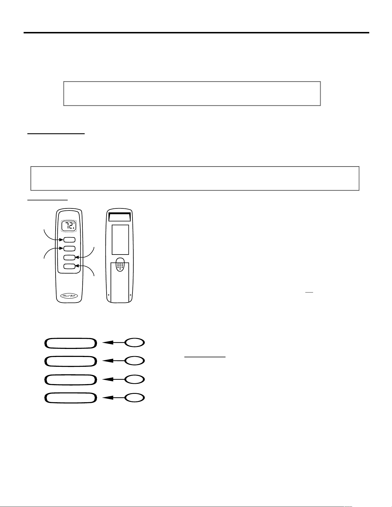
(67@?3:<A31<;A?<9'-'("<443?@A63B@3?/0/AA3?F<=3?/A32?3:<A31<;A?<9A<
=<D3? / 9/A167;5 @<93;<72 @B16 /@ A6<@3 B@32 D7A6 5/@ C/9C3@ B@32 7; @<:3
63/A3??/A325/@9<5@5/@47?3=9/13@/;2<A63? 5/@63/A7;5/==97/;13@
(63 @<93;<72 17?1B7A B@3@ A63 0/AA3?F =<D3? 4?<: A63 ?3137C3? A< <=3?/A3 /
@<93;<72(6317?1B7A6/@?3C3?@7;5=<9/?7AF@<4AD/?3D6716?3C3?@3@A63=<@7A7C3
/;2 ;35/A7C3 <BA=BA <4 A63 ?3137C3?@ 0/AA3?F =<D3? A< 2?7C3 / 9/A167;5
@<93;<72$#$(63'-'("7@1<;A?<99320FA63?3:<A3A?/;@:7AA3?
(63A?/;@:7AA3?<=3?/A3@<;/*0/AA3?73@
! !#0/AA3?73@@6<B92/9D/F@03B@324<?9<;53?0/AA3?F9743/;2:/E7:B:
<=3?/A7<;/9=3?4<?:/;13&316/?53/0930/AA3?73@@6<B92;<A 03B@32
34<?3 B@7;5 A63 A?/;@:7AA3? 7;@A/99 A63 A?/;@:7AA3? 0/AA3?73@ 7;A< A63
0/AA3?F 1<:=/?A:3;A )@3 1/BA7<; A6/A 0/AA3?73@ /?3 7;@A/9932 7; A63 =?<=3?
27?31A7<;
'!""!
$#$=3?/A3@B;7AA<<;=<@7A7<;"/;B/99F<=3?/A32@<93;<72$#
$$=3?/A3@B;7AA<<44=<@7A7<;"/;B/99F<=3?/A32@<93;<72$
"$6/;53@B;7A4?<::/;B/9:<23A<A63?:<:<23
'('3A@A3:=3?/AB?37;A63?:<:<23
ON
MODE
OFF
SET
1
2
3
4
ON
MODE
OFF
BUTTON
WALL CLIP
SLOT
BATTERY
COMPARTMENT
FRONT BACK
OFF
SET
ON
BUTTON
MODE
BUTTON
SET
BUTTON
IF YOU CANNOT READ OR UNDERSTAND THESE INSTALLATION
INSTRUCTIONS DO NOT ATTEMPT TO INSTALL OR OPERATE
5HYLHZ&20081,&$7,216$)(7<XQGHU*(1(5$/,1)250$7,21VHFWLRQ7KLV
VDIHW\IHDWXUHVKXWVGRZQWKHDSSOLDQFHZKHQDSRWHQWLDOO\XQVDIHFRQGLWLRQH[LVWV
28
REMOTE CONTROL OPERATION
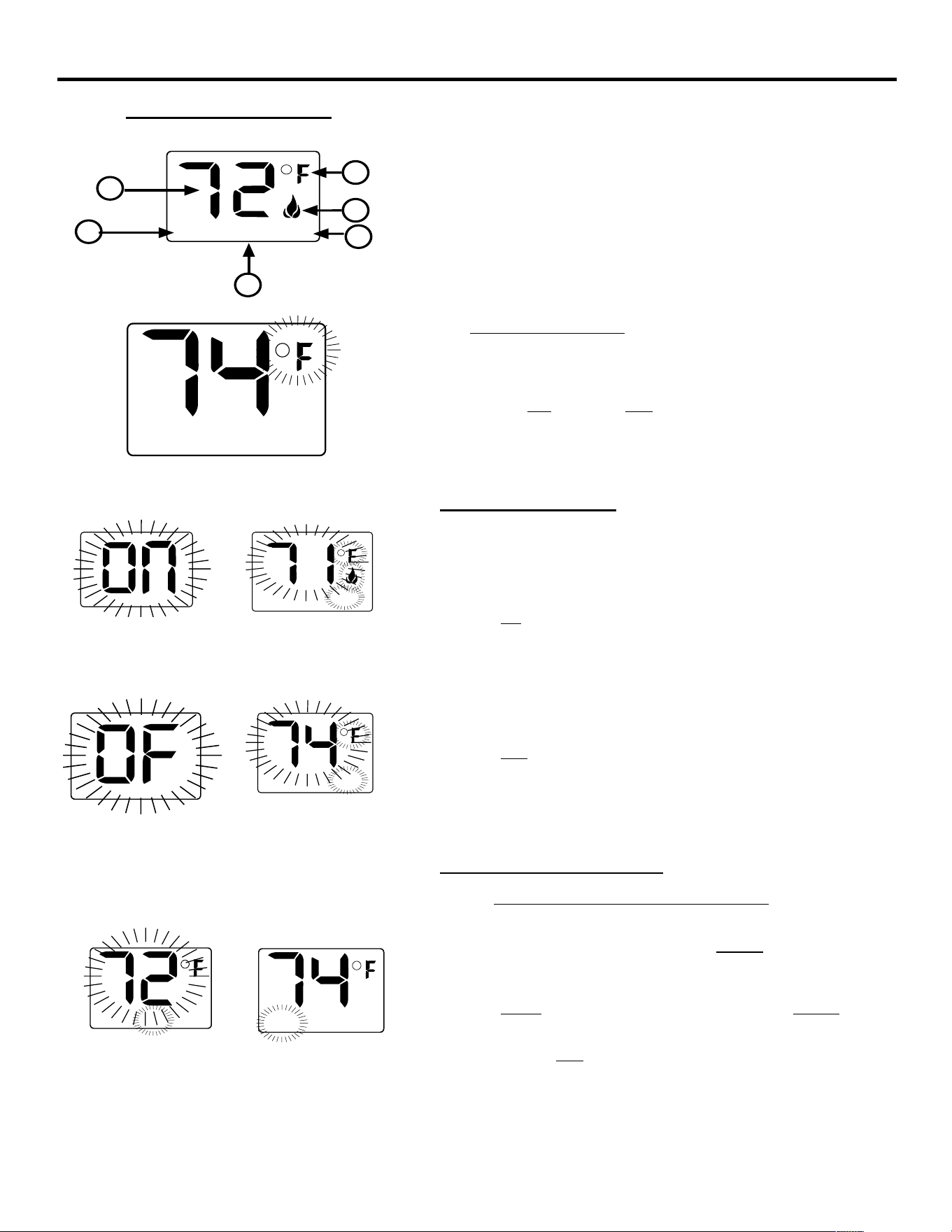
!' ;271/A3@)&&#(?<<:A3:=3?/AB?3
$&
;271/A3@235?33@/6?3;637A<?39@7B@
;271/A3@0B?;3?C/9C37;<=3?/A7<;
;271/A3@?3:<A37@7;(&"$<=3?/A7<;
" ==3/?@2B?7;5:/;B/9<=3?/A7<;
!" ==3/?@2B?7;5A7:3A63<4@3AA7;5A63 23@7?32
A3:=3?/AB?37; A63A63?:<<=3?/A7<;
!""
!
(634/1A<?F@3AA7;54<?A3:=3?/AB?37@
(<16/;53A67@@3AA7;5A<
47?@A
• %?3@@A63$#83F/;2A63$ 83F<;A63A?/;@:7AA3?/AA63@/:3
A7:3A67@D79916/;534?<:
A<
<99<DA67@@/:3=?<132B?3A<
16/;534?<:
0/18A<
##"
(<<=3?/A3A63@F@A3:7;A63:/;B/9K"$L2<A634<99<D7;5
$#$%&($#
%?3@@A63$# 83FA63/==97/;1349/:3D7991<:3<;B?7;5A67@A7:3A63
!@1?33;D799@6<D$#/4A3?@31<;2@A63!@1?33;D799234/B9A
A<27@=9/F?<<:A3:=3?/AB?3/;2A63D<?2("%D799@6<D1)2-0+43
;01)55-)6437+6--3032)39)14324,-
$$%&($#
%?3@@A63$ 83FA63/==97/;1349/:3D799@6BA<44B?7;5A67@A7:3A63
!@1?33;D799@6<D$/4A3?@31<;2@A63!@1?33;D799234/B9AA<
27@=9/F?<<:A3:=3?/AB?3/;2A63D<?2("%D799@6<D
" !""#"
!""! " "#
(67@ ?3:<A31<;A?<9 @F@A3:1/;03A63?:<@A/A71/99F 1<;A?<9932D63;A63
A?/;@:7AA3?7@7;A63(&"$:<23(63D<?2 2978 *-
,0751)=-,438/-7+6--3(<@3A A63 (&"$ "$ /;2 '&
?<<: A3:=3?/AB?3
%?3@@A63 "$83FB;A79 A63 !@1?33;@6<D@A63 D<?2 &$$"
A63; A63?3:<A37@7;A63A63?:<@A/A71:<23
%?3@@/;2 6<92 A63 '(83FB;A79 A63 23@7?32@3A A3:=3?/AB?37@
?3/1632 F=?3@@7;5 /;2 6<927;5A63@3A83FA63!@1?33;@3A
;B:03?@ D799 7;1?3/@34?<:
A<
A63;?3@A/?A<C3?/A
#3EA
TEMP
TEMPSET
" !"
'&#+!
%&''#$
-
TEMP
'&#(&
'$#)!(
ROOM
TEMP
"
TEMP
'&#(&
'$#)!(
ROOM
LCD - Liquid Crystal Display
TEMP
1
2
3
SET
4
5
6
'&#+!
%&''#$#
-
29
REMOTE CONTROL OPERATION
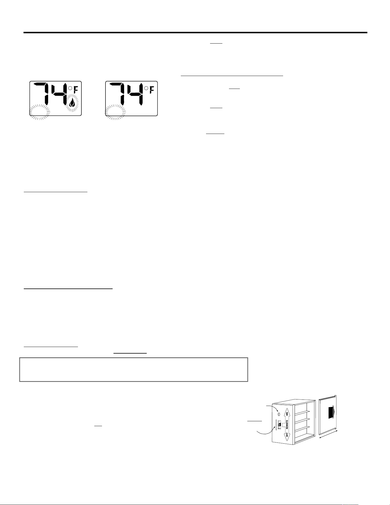
?393/@3A63'(83F(63!@1?33;D79927@=9/FA63@3AA3:=3?/AB?3
4<?@31<;2@/;2A63!@1?33;D79949/@6A63@3AA3:=3?/AB?34<?
@31<;2@A63;A63!@1?33;D799234/B9AA<27@=9/FA63?<<:
A3:=3?/AB?3
($#('(("%&()&
%?3@@/;26<92A63'( 83FB;A79A6323@7?32@3AA3:=3?/AB?37@
?3/1632F=?3@@7;5/;26<927;5A63@3A83FA63!@1?33;@3A
;B:03?@D7997;1?3/@34?<:
A<
A63;?3@A/?A<C3?/A
#3EA
?393/@3A63'(83F(63!@1?33;D79927@=9/FA63@3AA3:=3?/AB?3
4<?@31<;2@A63;D79949/@6A63@3AA3:=3?/AB?34<?@31<;2@A63;A63
!@1?33;D799234/B9AA<27@=9/FA63?<<:A3:=3?/AB?3
%?3@@A63"$ 83FA<27@3;5/53A63A63?:<:<23(63D<?2&$$"
<;A63!@1?33;D799;<A@6<DD63;A63A63?:<7@;<A7;<=3?/A7<;
#$((6367563@A'(A3:=3?/AB?37@
)/6-3/-08
39@7B@
/;2A639<D3@AA3:=3?/AB?37@
)/6-3/-08
39@7B@
""!
(63(63?:<3/AB?3<;A63A?/;@:7AA3?<=3?/A3@A63/==97/;13D63;3C3?A63&$$"("%&()&C/?73@/13?A/7;;B:03?<4
235?33@4?<:A63'(("%&()&(67@C/?7/A7<;7@1/9932A63K'+#L<?("%&()&&#(!(63;<?:/9
<=3?/A7;51F193<4/;/==97/;13:/F03A7:3@=3?6<B?23=3;27;5<;6<DD399A63?<<:<?6<:37@7;@B9/A324?<:A631<92<?2?/4A@
(634/1A<?F@3AA7;54<?A63K@D7;5;B:03?L7@(67@?3=?3@3;A@/A3:=3?/AB?3C/?7/A7<;<4
03AD33;'(A3:=3?/AB?3
/;2&$$"A3:=3?/AB?3D671623A3?:7;3@D63;A6347?3=9/13D79903/1A7C/A32
(63A?/;@:7AA3?6/@$#/;2$:/;B/94B;1A7<;@A6/A/?3/1A7C/A320F=?3@@7;537A63?0BAA<;<;A634/13<4A63A?/;@:7AA3? +63;/
0BAA<;<;A63A?/;@:7AA3?7@=?3@@32A63D<?2$#<?$D799/==3/?<;A63!@1?33;A<@6<DD6793A63@75;/97@037;5@3;A)=<;
7;7A7/9B@3A63?3:/F03/239/F<4A6?33@31<;2@034<?3A63?3:<A3?3137C3?D799?3@=<;2A<A63A?/;@:7AA3?(67@7@=/?A<4A63@F@A3:@
23@75;
% !""?"
(633931A?<;71@7;A63?3:<A31<;A?<9@F@A3:6/C3A631/=/0797AF<4=<D3?7;5AD<27443?3;AAF=3@<4=<D3?321<:=<;3;A@4/;F
<=3?/A7<;/9=?<093:@/?3;<A321<;A/1AB@A<:3?'3?C713
(63&*&1<:3@4?<:A634/1A<?F=?<5?/::32 A<=?<C723=B9@3C<9A/53*A<*A</9/A167;5@<93;<72
" $
""
" " $ !#!"% "
" "# !"&>
(63 ?3:<A3 ?3137C3? ?756A <=3?/A3@ <; * @7G3 0/AA3?73@ A 7@
?31<::3;232A6/A! !#0/AA3?73@03B@324<?9<;53?0/AA3?F9743/;2:/E7:B:
:71?<=?<13@@<? =3?4<?:/;13 "%$&(#( #3D <? 4B99F 16/?532 0/AA3?73@ /?3
3@@3;A7/9 A< =?<=3? <=3?/A7<; <4 A63 ?3:<A3 ?3137C3? /@ / 9/A167;5 @<93;<72 =<D3?
1<;@B:=A7<; 7@ @B0@A/;A7/99F 67563? A6/; @A/;2/?2 ?3:<A3 1<;A?<9 @F@A3:@ &3
16/?53/0930/AA3?73@@6<B92;<A 03B@32
#$((63?3:<A3?3137C3?D799<;9F?3@=<;2A<A63A?/;@:7AA3?D63;A63=<@7A7<;
@97230BAA<;<;A63?3:<A3?3137C3?7@7;A63&"$(=<@7A7<;(63?3:<A3?3137C3?
6<B@3@ A63 :71?<=?<13@@<? A6/A ?3@=<;2@ A< 1<::/;2@ 4?<: A63 A?/;@:7AA3? A<
1<;A?<9@F@A3:<=3?/A7<;
ROOM
TEMP
"
ROOM
TEMP
"
REMOTE
ON
OFF
LEARN
Requires 4-AA 1.5V
alkaline batteries
Learning
button
Remote Receiver
Battery cover slides on/off
Slide
Switch
ON
REMOTE
OFF
7+(5(027(5(&(,9(56+28/'%(326,7,21(':+(5($0%,(17
7(03(5$785(6'2127(;&((')
30
REMOTE CONTROL OPERATION
#"!
• +7A6A63@9723@D7A167;A63&"$(=<@7A7<;A63@F@A3:D799<;9F<=3?/A3
74A63?3:<A3?3137C3??3137C3@1<::/;2@4?<:A63A?/;@:7AA3?
• )=<;7;7A7/9B@3<?/4A3?/;3EA3;232=3?7<2<4;<B@3A63$#0BAA<;:/F
6/C3A<03=?3@@324<?B=A<A6?33@31<;2@034<?3/1A7C/A7;5@3?C<:<A<?4
A63 @F@A3: 2<3@ ;<A ?3@=<;2 A< A63 A?/;@:7AA3? <; 7;7A7/9 B@3 @33
!&##(&#'"((&($&*&
• +7A6 A63 @9723 @D7A16 7; A63 $# =<@7A7<; F<B 1/; :/;B/99F AB?; $# A63
@F@A3:
• +7A6A63@97237;A63$=<@7A7<;A63@F@A3:7@$
• A7@@B553@A32A6/AA63@9723@D7A1603=9/1327;A63$=<@7A7<;74F<BD799
03/D/F4?<:F<B?6<:34<?/;3EA3;232=3?7<2<4A7:3
• %9/17;5 A63 @9723 @D7A16 7; A63 $ =<@7A7<; /9@< 4B;1A7<;@ /@ /
@/43AF9<18<BA0F0<A6AB?;7;5A63@F@A3:$/;2?3;23?7;5A63
A?/;@:7AA3?7;<=3?/A7C3
!""!" #"!
%
" " " $ "' " $ % "! % #
#" " $ % !" #"! #"# ! $$
" % # ! !"" " "!
#!"!$$ " $
!""
(63?3:<A3?3137C3?1/;03:<B;A32<;<?;3/?A6347?3=9/1363/?A6%&$(($#&$",(&"('*&-"%$&(#(
!783 /;F =7313 <4 3931A?<;71 3>B7=:3;A A63 ?3:<A3 ?3137C3? @6<B92 03 83=A /D/F 4?<: A3:=3?/AB?3@ 3E13327;5 I 7;@723 A63
?3137C3?1/@3/AA3?F97437@/9@<@75;7471/;A9F@6<?A3;32740/AA3?73@/?33E=<@32A<6756A3:=3?/AB?3@
"#"
(63 ?3:<A3 ?3137C3? 1/; 03 =9/132 <; A63 47?3=9/13 63/?A6 <? B;23? A63 47?3=9/13 0367;2 A63
1<;A?<9/113@@=/;39 %<@7A7<;D63?3A63/:073;AA3:=3?/AB?37;@723A63?3137C3?1/@32<3@;<A
3E1332I"9/18BAA<;7@B@32<;3/?A6"<B;A==971/A7<;@
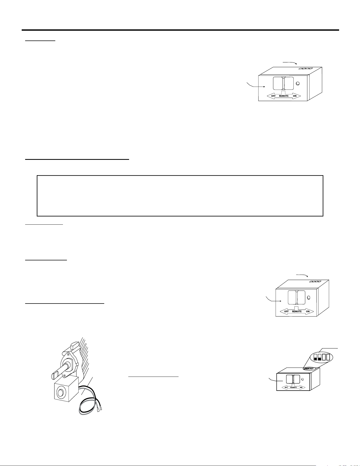
% !" #"!
"/83@B?3A63?3:<A3?3137C3?@D7A167@7;A63$=<@7A7<;<?03@A?3@B9A@7A7@?31<::3;232
A6/A5/B53@A?/;232D7?3@@6<B9203B@32A<:/831<;;31A7<;@/;2;<9<;53?A6/;433A
(67@$#(?3:<A3?3137C3?7@A<031<;;31A32
A</:/;B/9C/9C3D7A6/9/A167;5$#$@<93;<72
<;;31AAD<5/B53@A?/;232<?@<972 D7?3@4?<:A63
?3:<A3 ?3137C3? A3?:7;/9@ A< A63 9/A167;5 @<93;<72
'33475B?3A<A63?756A
"" "$=3?/A7<; <4 A67@ 1<;A?<9 7@
23=3;23;A<;D6716D7?37@/AA/1632A<D6716A3?:7;/9
4<=3?/A7<;<41<;A?<92<3@;<A1<??3@=<;2A<<=3?/A7;5
0BAA<;@ <; A?/;@:7AA3? ?3C3?@3D7?3 7;@A/99/A7<; /A A63
?3137C3?<?/AA631<;A?<9
Black Wire
Red Wire
Pulse Connection
Concentric Valve
Wire terminals
Remote Receiver
Receiver
Slide
Button
REMOTE
OFF
ON
LEARN
Wire terminals
Remote Receiver
Receiver
Slide
Button
REMOTE
OFF
ON
LEARN
Remote Receiver
Receiver
Slide
Button
REMOTE
OFF
PULSE MODE
Terminals
LEARN
ON
'2127&211(&75(027(5(&(,9(5',5(&7/<729$&32:(57+,6:,//%851
2877+(5(&(,9(5)2//2:,16758&7,216)5200$18)$&785(52)*$69$/9()25
CORRECT WIRING PROCEDURES. IMPROPER INSTALLATION OF ELECTRIC COMPONENTS CAN
&$86('$0$*(72*$69$/9($1'5(027(5(&(,9(5

31
REMOTE CONTROL OPERATION
"
#"?!"'?" !""
(67@?3:<A31<;A?<96/@/$"")#($#J'(-4B;1A7<;0B79A7;A<7A@@<4AD/?3A=?<C723@/;3EA?/:/?57;<4@/43AFD63;A63
(&#'"((&7@<BA<4A63;<?:/94<<A<=3?/A7;5?/;53<4A63?3137C3?
(63$"")#($#J'(-43/AB?3<=3?/A3@7;A634<99<D7;5:/;;3?7;/99$%&(#"$'J$#$#(&"$
A/99A7:3@/;27;/99$%&(#"$'A63A?/;@:7AA3?@3;2@/;&@75;/93C3?F474A33;:7;BA3@A<A63?3137C3?7;271/A7;5
A6/A A63 A?/;@:7AA3? 7@ D7A67; A63 ;<?:/9 <=3?/A7;5?/;53 <4 433A '6<B92 A63 ?3137C3?#$( ?3137C3 / A?/;@:7AA3? @75;/9 3C3?F
:7;BA3@A63@<4AD/?37;A63&*&D7990357;/$)&:7;BA31<B;A2<D;A7:7;54B;1A7<;42B?7;5A67@6<B?=3?7<2
A63?3137C3?2<3@;<A?3137C3/@75;/94?<:A63A?/;@:7AA3?A63?3137C3?D799@6BA2<D;A63/==97/;13037;51<;A?<99320FA63?3137C3?
(63 &*& D799 A63; 3:7A / @3?73@ <4 ?/=72 K033=@L 4<? / =3?7<2 <4 @31<;2@ (63; /4A3? @31<;2@ <4 ?/=72 033=7;5 A63
&*& D799 1<;A7;B3 A< 3:7A / @7;593 K033=L 3C3?F @31<;2@ B;A79 / A?/;@:7AA3? $# <? "$ BAA<; 7@ =?3@@32 A< ?3@3A A63
?3137C3?(637;A3?:7AA3;A@31<;2033=7;5D7995<<;4<?/@9<;5/@A63?3137C3?M@0/AA3?73@9/@AD67161<B92037;3E13@@<4<;3F3/?
(< K?3@3AL A63 &*& /;2 <=3?/A3 A63 /==97/;13 F<B :B@A =?3@@ A63 $# <? "$ 0BAA<; <; A63 A?/;@:7AA3? F AB?;7;5 A63
@F@A3:A<$#A63$"")#($#'(-<=3?/A7<;7@<C3??7223;/;2A63@F@A3:D799?3AB?;A<;<?:/9<=3?/A7<;23=3;27;5<;
A63"$@3931A32/AA63A?/;@:7AA3?(63$"")#($#J'(-43/AB?3D799?3/1A7C/A3@6<B92A63A?/;@:7AA3?03A/83;<BA<4
A63;<?:/9<=3?/A7;5?/;53<?@6<B92A63A?/;@:7AA3?M@0/AA3?73@4/79<?03?3:<C32
"#
(67@?3:<A31<;A?<97;19B23@/!%&$$K!$ $)(L43/AB?3A6/A/99<D@A63B@3?A<K!$ $)(L<=3?/A7<;<4A63/==97/;13
4?<:A63(&#'"((&
!""@#"A?
• (</1A7C/A3A63K!$ $)(L43/AB?3=?3@@/;26<92A63$#0BAA<;/;2A63"$0BAA<;/AA63@/:3A7:34<?@31<;2@(63
93AA3?@%D799/==3/?7;A63("%4?/:3<;A63!@1?33;
• (<27@3;5/53A63K!$ $)(L=?3@@/;26<92A63$#0BAA<;/;2A63"$0BAA<;/AA63@/:3A7:34<?@31<;2@/;2A6393AA3?@
%D79927@/==3/?4?<:A63!@1?33;/;2A63A?/;@:7AA3?D799?3AB?;A<7A@;<?:/9<=3?/A7;51<;27A7<;
• (<C3?74FA6/AA?/;@:7AA3?7@7;A63%9<18<BA:<23=?3@@/;F83F/;2A63!@1?33;D799@6<DK%L
#$(4A63/==97/;137@/9?3/2F<=3?/A7;57;A63$#<?(&"$"$'3;5/57;5A63K!$ $)(LD799;<A1/;139A63<=3?/A7;5
"$;5/57;5A63K!$ $)(L=?3C3;A@<;9FA63:/;B/9<=3?/A7<;<4A63(&#'"((&47;A63/BA<:<23@A63(&"$
<=3?/A7<;D7991<;A7;B3A<<=3?/A3;<?:/99F(<A<A/99FK!$ $)(LA63<=3?/A7<;<4A63(&#'"((&M'<=3?/A7;5@75;/9@A63
A?/;@:7AA3?M@"$:B@A03@3AA<$
" !"" " $
/16A?/;@:7AA3?B@3@/B;7>B3@31B?7AF1<23AD79903;313@@/?FA<=?3@@A63!�BAA<;<;A63?3137C3?A</113=AA63A?/;@:7AA3?
@31B?7AF1<23B=<;7;7A7/9B@3740/AA3?73@/?3?3=9/132<?74/?3=9/13:3;AA?/;@:7AA3?7@=B?16/@324?<:F<B?23/93?<?A634/1A<?F;
<?23?4<?A63?3137C3?A</113=AA63A?/;@:7AA3?@31B?7AF1<2303@B?3A63@97230BAA<;<;A63?3137C3?7@7;A63&"$(=<@7A7<;A63
?3137C3?D799348!JA63@9723@D7A167@7;A63$#<?$=<@7A7<;(63!�BAA<;7;9<1/A32<;A634?<;A4/13<4A63?3137C3?
7;@723A63@:/996<939/03932!&#)@7;5/@:/99@1?3D2?7C3?<?3;2<4/=/=3?197=53;A9F=?3@@/;2?393/@3A6309/18!�BAA<;
7;@723A636<93+63;F<B?393/@3A63!�BAA<;A63?3137C3?D7993:7A/;/B27093K033=L4A3?A63?3137C3?3:7A@A63033==?3@@
A63A?/;@:7AA3?#-0BAA<;/;2?393/@3(63?3137C3?D7993:7A@3C3?/9033=@7;271/A7;5A6/AA63A?/;@:7AA3?M@1<236/@033;/113=A32
7;A<A63?3137C3?
(63:71?<=?<13@@<?A6/A1<;A?<9@A63@31B?7AF1<23:/A167;5=?<132B?37@1<;A?<99320F/A7:7;54B;1A7<;4F<B/?3B;@B113@@4B97;
:/A167;5A63@31B?7AF1<23<;A6347?@A/AA3:=AD/7A:7;BA3@034<?3A?F7;5/5/7;A67@239/F/99<D@A63:71?<=?<13@@<?A<?3@3A7A@
A7:3?17?1B7A?F/;2A?FB=A<AD<<?A6?33:<?3A7:3@

32
REMOTE CONTROL OPERATION
"" '
&3=9/13/990/AA3?73@?35B9/?9F+63;A63A?/;@:7AA3?;<9<;53?<=3?/A3@A63?3:<A3?3137C3?4?<:/27@A/;137A272=?3C7<B@9F73A63
A?/;@:7AA3?@?/;536/@231?3/@32<?A63?3:<A3?3137C3?2<3@;<A4B;1A7<;/A/99A630/AA3?73@@6<B92031631832A7@7:=<?A/;AA6/A
A63 ?3:<A3?3137C3?0/AA3?73@/?34B99F16/?532=?<C727;51<:07;32<BA=BAC<9A/53<4/A93/@AC<9A@(636/;26392A?/;@:7AA3?@6<B92
<=3?/A3D7A6/@97AA93/@C<9A@0/AA3?F=<D3?
" # !"
4F<B 3;1<B;A3? =?<093:@ D7A6 F<B? 47?3=9/13 @F@A3: A63 =?<093: :/F 03 A63 47?3=9/13 7A@394 <? 7A1<B92 03 D7A6 A63 ?3:<A3
@F@A3:&3C73DA6347?3=9/13:/;B4/1AB?3?@<=3?/A7<;:/;B/9A<:/83@B?3/991<;;31A7<;@/?3=?<=3?9F:/23(63;16318 A63
<=3?/A7<;<4A63?3:<A37;A634<99<D7;5:/;;3?
• "/83@B?3A630/AA3?73@/?31<??31A9F7;@A/99327;A63&*&$;3?3C3?@320/AA3?FD799833=?3137C3?4?<:<=3?/A7;5=?<=3?9F
• 63180/AA3?F7;(&#'"((&A<3;@B?31<;A/1A@/?3A<B167;5/;23;2@<40/AA3?F3;2:3A/91<;A/1A@7;4<?A756A3?47A
• 3@B?3&*&/;2(&#'"((&7@D7A67;433A <=3?/A7;5?/;53
• 93/?<23@"3:<?F7;A63?3137C3?:756A034B9974A6393/?;0BAA<;7@=?3@@32A<<:/;FA7:3@4A67@6/==3;@7AD799;<A/99<D/;F
:<?31<23@A<0393/?;32/;2;</B27093033=D7990363/?2(<193/?:3:<?F=9/13A63?3137C3?@9723@D7A167;A<A63&"$(
=<@7A7<;%?3@@A6393/?;0BAA<;/;2?393/@3/4A3?@31<;2@-<B@6<B9263/?A6?339<;5/B27093033=@7;271/A7;5/991<23@
6/C3193/?32-<B1/;;<DK93/?;LA63A?/;@:7AA3?A<A63?3137C3?/@23@1?70327;A633;3?/9;4<?:/A7<;'31A7<;
• 33=&*&4?<:A3:=3?/AB?3@3E13327;5H/AA3?F9743@6<?A3;32D63;/:073;AA3:=3?/AB?3@/?3/0<C3H
• 4&*&7@7;@A/99327;A756A9F3;19<@32:3A/9@B??<B;2A63<=3?/A7;527@A/;13D79903@6<?A3;32
• &316/?53/0930/AA3?73@@6<B92;<A03B@32(63F2<;<A@B==9F@B447173;A=<D3?A<<=3?/A3A63?3:<A3@F@A3:
!"!
((&' (?/;@:7AA3?C<9AA0/A3?73@
&3:<A3&3137C3?*3/ 98/97;3
#<@ A?/;@:7AA3?$5/6*+&
# "!
""#"# !" !! ' "$" #!'
##" ("!""!#"!#"!#$"#! B!
#" "'" ""#"
FCC REQUIREMENTS
127(7+(0$18)$&785(5,61275(63216,%/()25$1<5$',22579,17(5)(5(1&(&$86('%<
81$87+25,=('02',),&$7,216727+,6(48,30(1768&+02',),&$7,216&28/'92,'7+(86(5¶6
AUTHORITY TO OPERATE THE EQUIPMENT.
33
OPERATION
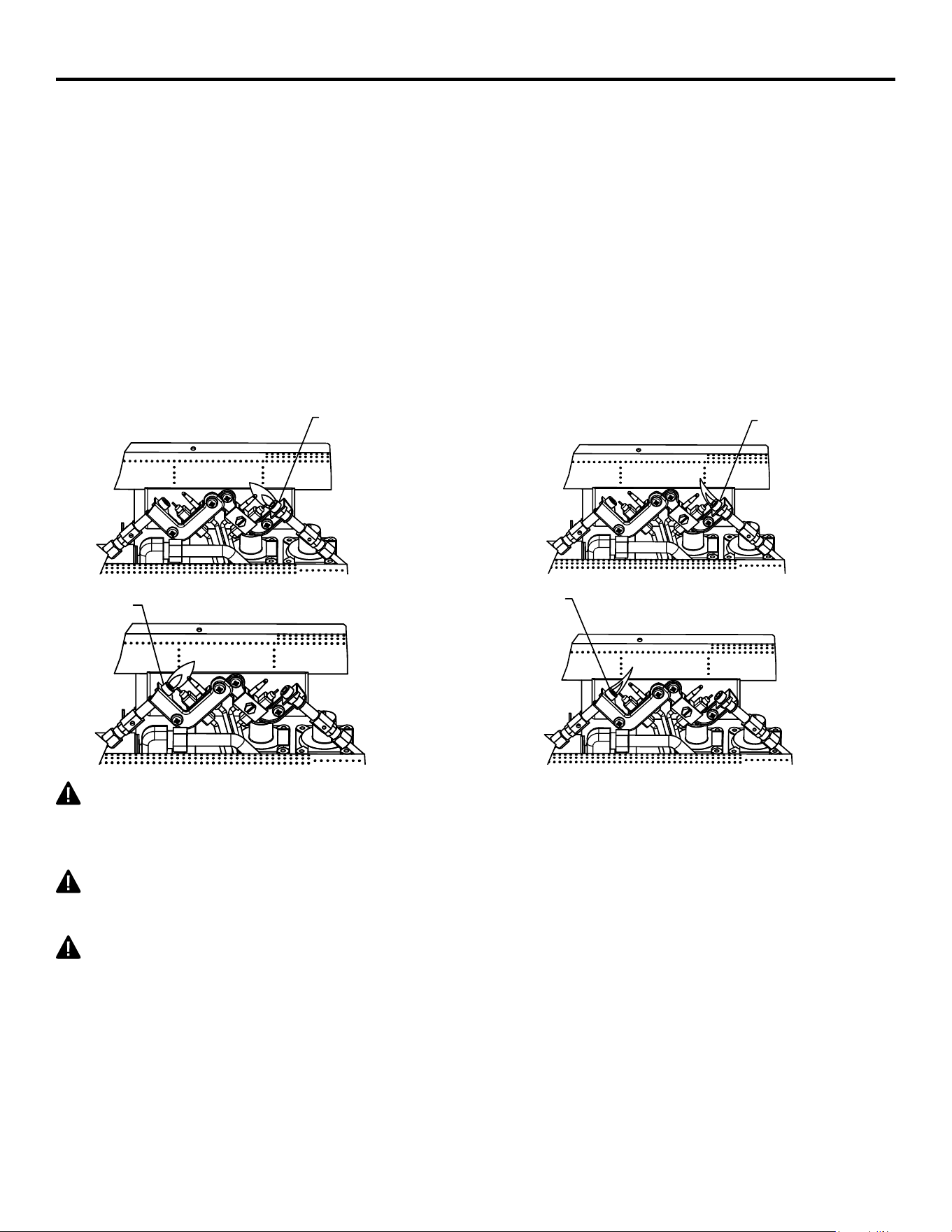
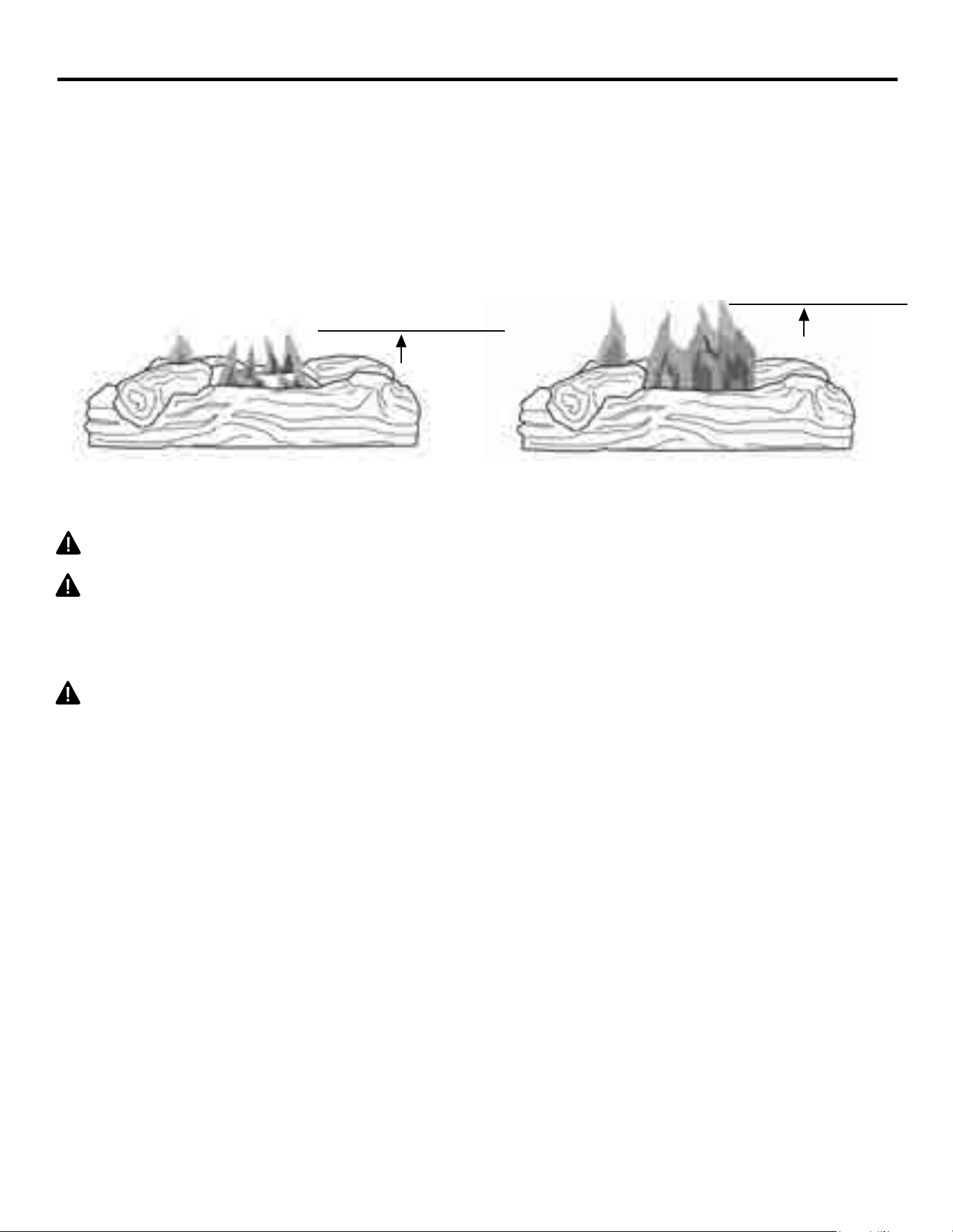
INSPECTING BURNERS
&KHFNSLORWÀDPHSDWWHUQDQGEXUQHUÀDPHSDWWHUQVRIWHQ
PILOT FLAME PATTERN
)LJXUHVKRZVDFRUUHFWSLORWÀDPHSDWWHUQ)LJXUHVKRZVDQLQFRUUHFWSLORWÀDPHSDWWHUQ7KH
LQFRUUHFWSLORWÀDPHLVQRWWRXFKLQJWKHWKHUPRFRXSOH7KLVZLOOFDXVHWKHWKHUPRFRXSOHWRFRRO:KHQ
WKHWKHUPRFRXSOHFRROVWKH¿UHSODFHZLOOVKXWGRZQ
,ISLORWÀDPHSDWWHUQLVLQFRUUHFWDVVKRZQLQ)LJXUH
WXUQ¿UHSODFHRႇVHH7R7XUQ2ႇ*DVWR$SSOLDQFHSDJH
• see Troubleshooting, page 34.
1RWH7KHSLORWÀDPHRQQDWXUDOJDVXQLWVZLOOKDYHDVOLJKWFXUYHEXWÀDPHVKRXOGEHEOXHDQGKDYH
no yellow or orange color.
WARNING: If yellow tipping occurs, your heater could produce increased levels of carbon
PRQR[LGH,IEXUQHUÀDPHSDWWHUQVKRZV\HOORZWLSSLQJIROORZLQVWUXFWLRQVDWERWWRPRIWKLV
page.
WARNING'RQRWDOORZIDQVWREORZGLUHFWO\LQWRWKH¿UHSODFH$YRLGDQ\GUDIWVWKDWDOWHUEXUQHU
ÀDPHSDWWHUQV
WARNING: Do not use a blower insert, heat exchanger insert or other acessory not approved for
use with this heater.
1RWLFH'RQRWPLVWDNHRUDQJHÀDPHVZLWK\HOORZWLSSLQJ'LUWRURWKHU¿QHSDUWLFOHVHQWHUWKHKHDWHU
DQGEXUQFDXVLQJEULHISDWFKHVRIRUDQJHÀDPH
Fig. 20 - Correct Pilot Flame Pattern Fig. 21 - Incorrect Pilot Flame Pattern
A
LP PILOT
A
NG PILOT
A
LP PILOT
A
NG PILOT
34
CARE AND MAINTENANCE
WARNING:7XUQRႇKHDWHUDQGOHWFRROEHIRUHVHUYLFLQJ
CAUTION: You must keep control areas, burner, and circulating air passageways of heater
clean. Inspect these areas of heater before each use. Have heater inspected yearly by a
TXDOL¿HGVHUYLFHSHUVRQ+HDWHUPD\QHHGPRUHIUHTXHQWFOHDQLQJGXHWRH[FHVVLYHOLQW
from carpeting, bedding material, pet hair, etc.
WARNING: Failure to keep the primary air opening(s) of the burner(s) clean may result in sooting
and property damage.
BURNER ORIFICE HOLDER AND PILOT AIR INLET HOLE
The primary air inlet holes allow the proper amount of air to mix with the gas. This provides a clean
EXUQLQJÀDPH.HHSWKHVHKROHVFOHDURIGXVWGLUWOLQWDQGSHWKDLU&OHDQWKHVHDLULQOHWKROHVSULRUWR
each heating season. Blocked air holes will create soot. We recommend that you clean the unit every
WKUHHPRQWKVGXULQJRSHUDWLRQDQGKDYH¿UHSODFHLQVSHFWHG\HDUO\E\DTXDOL¿HG
service person.
We also recommend that you keep the burner tube and pilot assembly clean and free of dust and dirt.
To clean these parts we recommend using compressed air no greater than 30 PSI. Your local
computer store, hardware store or home center may carry compressed air in a can. If using
compressed air in a can, please follow the directions on the can. If you don’t follow directions on the
can, you could damage the pilot assembly.
BURNER FLAME PATTERN
)LJXUHVKRZVDFRUUHFWEXUQHUÀDPHSDWWHUQ)LJXUHVKRZVDQLQFRUUHFWEXUQHUÀDPHSDWWHUQ
7KHLQFRUUHFWEXUQHUÀDPHSDWWHUQVKRZVVSRUDGLFLUUHJXODUÀDPHWLSSLQJ7KHÀDPHVKRXOGQRWEH
dark or have an orange/reddish tinge.
1RWH:KHQXVLQJWKH¿UHSODFHWKH¿UVWWLPHWKHÀDPHZLOOEHRUDQJHIRUDSSUR[LPDWHO\RQHKRXUXQWLO
the log cures.
,IEXUQHUÀDPHSDWWHUQLVLQFRUUHFWDVVKRZQLQ)LJXUH
WXUQ¿UHSODFHRႇVHH7R7XUQ2ႇ*DVWR$SSOLDQFHSDJH
• see Troubleshooting, page 34.
2-3 inches
above logs
6-12 inches
above logs
Fig. 22 - Correct Burner Flame Pattern Fig. 23 - Incorrect Burner Flame
Pattern
35
CARE AND MAINTENANCE
LOG SET
• If you remove the log set for cleaning, refer to pages 20 & 21, for placement instructions.
• Replace log set if broken or chipped (dime sized or larger).
CABINET
$LU3DVVDJHZD\V
Use a vacuum cleaner or pressurized air to clean.
([WHULRU
Use a soft cloth dampened with a mild soap and water mixture. Wipe the cabinet to remove dust.
Fig. 24 - Primary Air Inlet
Slot on Burner Tube
6KXWRႇXQLWLQFOXGLQJSLORW$OORZXQLWWRFRROIRUDWOHDVWPLQXWHV
,QVSHFWEXUQHUSLORWDQGSULPDU\DLULQOHWKROHVRQRUL¿FHKROGHUIRUGXVWDQGGLUW6HH)LJ
3. Blow air through the ports/slots and holes in the burner.
&KHFNWKHRUL¿FHKROGHUORFDWHGDWWKHHQGRIWKHEXUQHUWXEHDJDLQ5HPRYHDQ\ODUJHSDUWLFOHV
of dust, dirt, lint or pet hair with a soft cloth or vacuum cleaner nozzle.
%ORZDLULQWRWKHSULPDU\DLUKROHVRQWKHRUL¿FHKROGHU
6. In case any large clumps of dust have now been pushed into the burner repeat steps 3 and 4.
&OHDQWKHSLORWDVVHPEO\DOVR$\HOORZWLSRQWKHSLORWÀDPHLQGLFDWHVGXVWDQGGLUWLQWKHSLORW
DVVHPEO\7KHUHLVDVPDOOSLORWDLULQOHWKROHDERXWIURPZKHUHWKHSLORWÀDPHFRPHVRXWRIWKH
SLORWDVVHPEO\VHH)LJXUHGHSHQGLQJRQPRGHO:LWKWKHXQLWRႇOLJKWO\EORZDLUWKURXJKWKHDLU
inlet hole. You may blow through a drinking straw if compressed air is not available.
Fig. 25 - Pilot Inlet Air Hole
LP Pilot Air
Inlet Hole
NG Pilot Air
Inlet Hole
A
Primary Air
Inlet Hole
Burne
r Tube
Shutter
Fig. 24 - Primary Air Inlet Hole
on Burner Tube
Burner
Tube
Primary Air
Inlet Slot
Shutter
A
LP PILOT
NG PILOT
DUAL FUEL MODELS
:HUHFRPPHQGWKDW\RXFOHDQWKHXQLWHYHU\WKUHHPRQWKVGXULQJRSHUDWLRQDQGKDYH¿UHSODFHLQVSHFWHG
\HDUO\E\DTXDOL¿HGVHUYLFHSHUVRQ)DLOXUHWRNHHSWKHSULPDU\DLURSHQLQJVRIWKHEXUQHUVFOHDQPD\
UHVXOWLQVRRWLQJDQGSURSHUW\GDPDJH
36
TROUBLESHOOTING
WARNING: If you smell gas:
6KXWRႇJDVVXSSO\
• Do not try to light any appliance.
• Do not touch any electrical switch; do not use any phone in your building.
• Immediately call your gas supplier from a neighbor’s phone. Follow the gas supplier’s instructions.
,I\RXFDQQRWUHDFK\RXUJDVVXSSOLHUFDOOWKH¿UHGHSDUWPHQW
IMPORTANT: Operating heater where impurities in air exist may create odors. Cleaning supplies, paint, paint
remover, cigarette smoke, cements and glues, new carpet or textiles, etc., create fumes. These fumes may mix
with combustion air and create odors.
WARNING: 0DNHVXUHWKDWSRZHULVWXUQHGRႇEHIRUHSURFHHGLQJ
WARNING:7XUQRႇDQGOHWFRROEHIRUHVHUYLFLQJ2QO\DTXDOL¿HGVHUYLFHSHUVRQVKRXOGVHUYLFH
and repair heater.
CAUTION: Never use a wire, needle, or similar object to clean ODS/pilot. This can damage ODS/ pilot unit.
352%/(0 3266,%/(&$86( &255(&7,9($&7,21
When ignitor button
is pressed in, there
is no spark at ODS/
pilot.
1. Ignitor electrode is
positioned wrong.
2. Ignitor electrode is broken.
3. Ignitor electrode is not
connected to ignitor cable.
4. Ignitor cable is pinched or
wet.
5. Damaged ignitor cable.
6. Bad push button ignitor.
1. Replace electrode.
2. Replace electrode.
3. Replace ignitor cable
4. Free ignitor cable if pinched by any
metal or tubing. Keep ignitor cable dry.
5. Replace ignitor cable.
6. Replace push button ignitor.
When ignitor button
is pressed in, there
is a spark at ODS/
pilot but no ignition.
*DVVXSSO\LVWXUQHGRႇRU
HTXLSPHQWVKXWRႇYDOYHLV
closed.
2. Control knob not fully
pressed in while pressing
ignitor button.
3. Air in gas lines when
installed.
4. ODS / pilot is clogged.
5. Gas regulator setting is not
correct.
6. Control knob not in PILOT
position.
7. Depleted gas supply (propane).
1. Turn on gas supply or open equipment
VKXWRႇYDOYH
2. Fully press in control knob while
pressing ignitor button.
3. Continue holding down control knob.
Repeat igniting operation until air is
removed.
4. Clean ODS/pilot (see Care and
Maintenance, page 33) or replace
ODS/pilot assembly.
5. Replace gas regulator.
6. Turn control knob to PILOT position.
7. Contact local propane/LP gas company.
6(59,&(+,176
:KHQ*DV3UHVVXUH,V7RR/RZ
• pilot will not stay lit
• burners will have delayed ignition
¿UHSODFHZLOOQRWSURGXFHVSHFL¿HGKHDW
• for propane/LP units, propane/LP gas supply may be low
You may feel your gas pressure is too low. If so, contact your local natural or propane/LP gas supplier.

37
TROUBLESHOOTING
352%/(0 3266,%/(&$86( &255(&7,9($&7,21
ODS/pilot lights
EXWÀDPHJRHVRXW
when control knob is
released.
1. Control knob is not fully
pressed in.
2. Control knob is not pressed
in long enough.
(TXLSPHQWVKXWRႇYDOYHLV
not fully open.
4. Thermocouple connection is
loose.
5. Thermocouple damaged.
6. Control valve damaged.
1. Press in control knob fully.
2. After ODS/pilot lights, keep control
knob pressed in 30 seconds.
)XOO\RSHQHTXLSPHQWVKXWRႇYDOYH
4. Hand tighten until snug, and then
tighten ¼ turn more.
5. Replace thermocouple.
6. Contact customer service.
Burner(s) does not
light afterODS/pilot
is lit.
%XUQHURUL¿FHLVFORJJHG
%XUQHURUL¿FHGLDPHWHULV
too small.
3. Inlet gas pressure is too low.
&OHDQEXUQHURUL¿FHVHH&DUHDQG
Maintenance, page 33) or contact
customer service.
2. Contact customer service.
3. Contact your gas supplier.
Delayed ignition of
burner(s).
1. Manifold pressure is too low.
%XUQHURUL¿FHLVFORJJHG
1. Contact your gas supplier.
2. Clean burner (see Care and Mainte-
nance, page 33) or contact customer
service.
%XUQHUEDFN¿ULQJ
during combustion.
%XUQHURUL¿FHLVFORJJHGRU
damaged.
2. Burner is damaged.
3. Gas regulator is damaged.
&OHDQEXUQHURUL¿FHVHH&DUHDQG
Maintenance, page 33 or contact
customer service.
2. Contact dealer or customer service.
3. Replace gas regulator.
+LJK\HOORZÀDPH
during burner
combustion
1. Not enough air.
2. Gas regulator is defective.
3. Inlet gas pressure is too low.
1. Check burner for dirt and debris. If found, clean
burner (see Care and Maintenance, page 33).
2. Replace gas regulator.
3. Contact your gas supplier.
Gas odor during
combustion.
1. Foreign matter between
control valve and burner.
2. Gas leak. (See Warning
Statement at top of page 34).
1. Take apart gas tubing and remove foreign
matter.
2. Locate and correct all leaks (see “Check-
ing Gas Connections,” page 22).
Heater produces a
clicking/ticking noise
just after burner is lit
RUVKXWRႇ
1. Metal is expanding while
heating or contracting
while cooling.
1. This is common with most heaters. If
QRLVHLVH[FHVVLYHFRQWDFWTXDOL¿HG
service technician.

38
TROUBLESHOOTING
352%/(0 3266,%/(&$86( &255(&7,9($&7,21
White powder resi-
due forming within
burner box or on
adjacent walls or
furniture.
1. When heated, the vapors
from furniture polish, wax,
carpet cleaners, etc., turn
into white powder residue.
7XUQKHDWHURႇZKHQXVLQJIXUQLWXUH
polish, wax, carpet cleaner or similar
products.
Heater produces
unwanted odors.
1. Heater is burning vapors
from paint, hair spray, glues,
etc. See IMPORTANT state-
ment, page 34.
2. Gas leak. See Warning
Statement, page 34.
3. Low fuel supply.
1. Ventilate room. Stop using odor
causing products while heater is
running.
2. Locate and correct all leaks (see
“Checking Gas Connections,” page 22).
5H¿OOVXSSO\WDQN3URSDQH/3PRGHOV
+HDWHUVKXWVRႇ
in use (ODS oper-
ates).
1. Not enough fresh air is
available.
2. Low line pressure.
3. ODS/pilot is partially
clogged.
1. Open window and/or door for
ventilation.
2. Contact local gas supplier.
3. Clean ODS/pilot (see Care and
Maintenance, page 33).
Gas odor exists
even when control
knob is in OFF posi-
tion.
1. Gas leak. See Warning
Statement at top of page 34.
2. Control valve is
defective.
1. Locate and correct all leaks (see
“Checking Gas Connections”, page 22).
2. Contact customer service.
Moisture/conden-
sation noticed on
windows.
1. Not enough combustion/
ventilation air.
1. Refer to “Air for Combustion and
Ventilation” requirements, page 9-11.
Slight smoke or
odor during initial
operation
Heater produces
a whistling noise
when burner is lit.
1. Residues from
manufacturing process.
1. Problem will stop after a few hours of
operation.
1. Turning control knob to high (5)
position when burner is cold.
2. Air in gas line.
3. Air passageways on
heater are blocked.
4. Dirty or partially clogged
EXUQHURUL¿FH
1. Turn control knob to low (1) position and
let warm up for a minute.
2. Operate burner until air is removed from
line. Have gas line checked by local
propane/LP gas company.
3. Observe minimum installation
clearances (Fig. 6, page 12)
4. Clean burner (see Care and Maintenance,
page 33) or contact customer service.
39
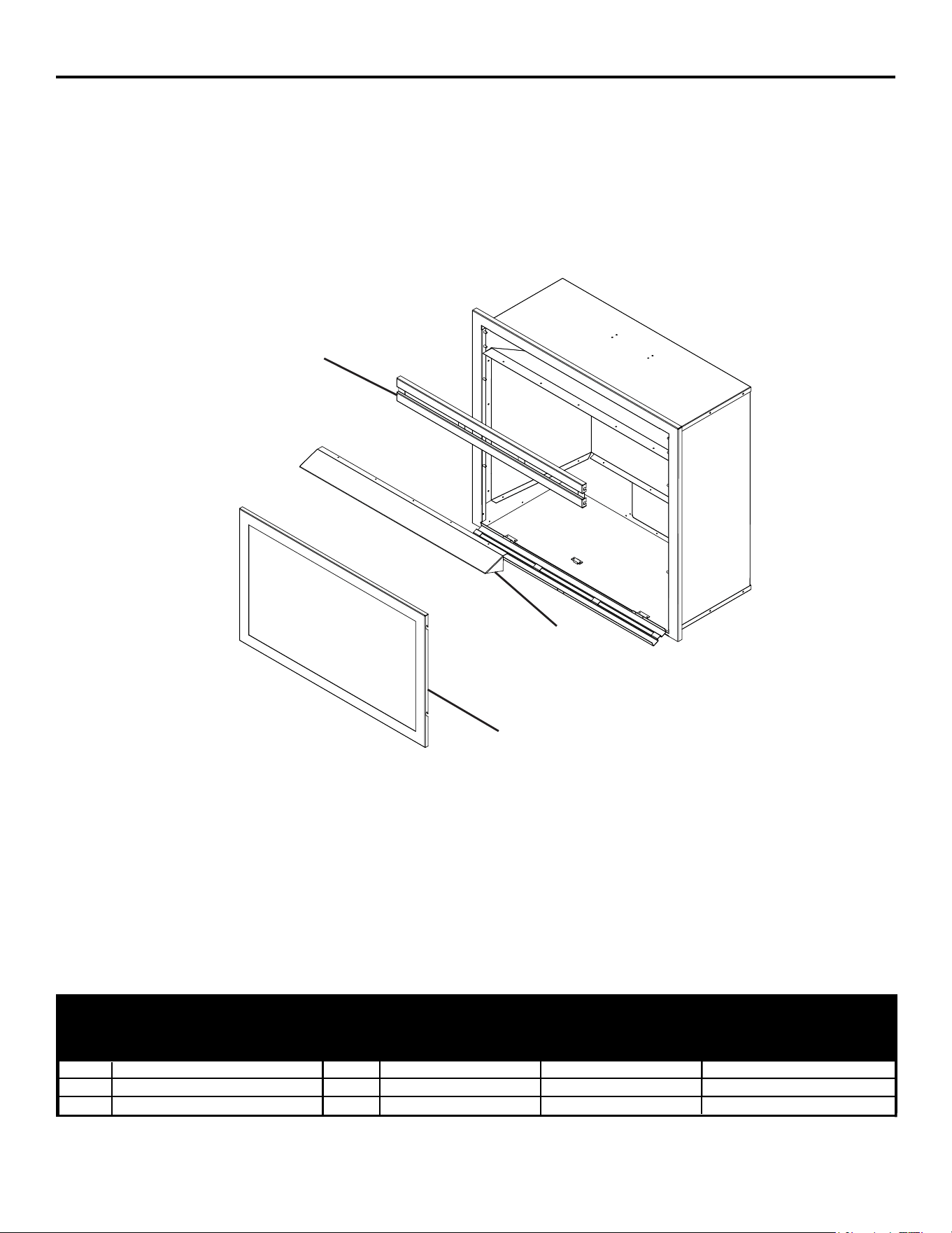
REPLACEMENT PARTS
For replacement parts, call our customer service department at 1-877-447-4768, 8:30 a.m. – 4:30 p.m.,
CST, Monday – Friday.
VFF2-PH(20D)(20DB)(20D-C)(CPD-2T), VFF2-PH(26D)(26DB)(26D-T)(IMD-2H),
VFF2-PH(32DR)(32DRB)(32DR-H)(FSDR-2C)
1
2
3
VFF2-PH20/CP Series
1 Top Grille 1 700-S1014B 700-M1014B
2 Hood 1 700-S1012B 700-M1012B
3 Window Frame Assembly 1 700-AS1015 700-AM1015
ITEM
No.
DESCRIPTION QTY
PART NUMBER
700-L1014B
700-L1012B
700-AL1015
VFF2-PH32/FS SeriesVFF2-PH26/IM Series
40
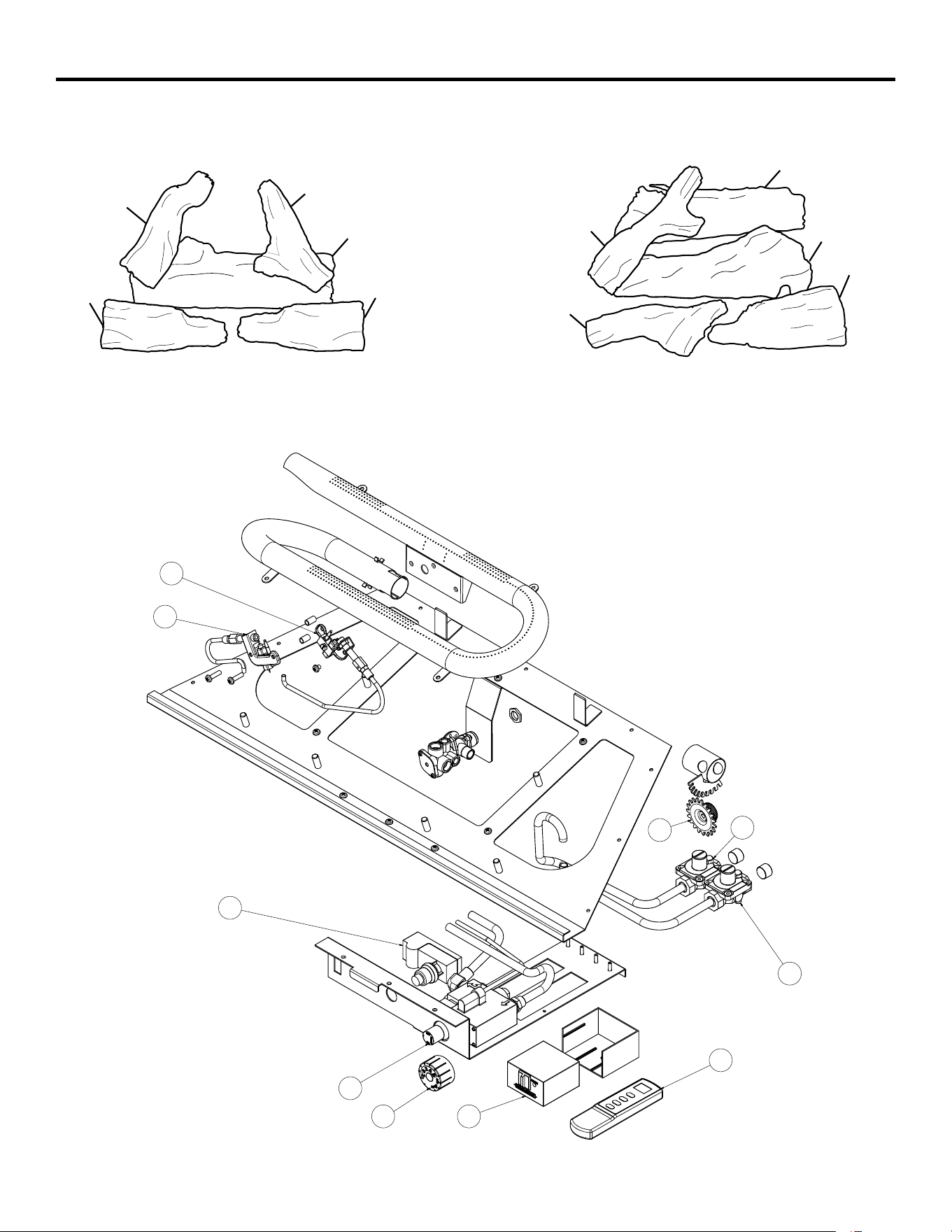
REPLACEMENT PARTS LIST
For replacement parts, call our customer service department at 1-877-447-4768, 8:30 a.m. – 4:30 p.m.,
CST, Monday – Friday.
9))3+''%'&&3'7
9))3+''%'7,0'+
9))3+'5'5%'5+)6'5&
1-1
1-2
1-3
1-5
1-4
1-1
1-2
1-3
1-5
1-4
2-3
2-4
4
3
2-8
2-6
2-1
2-2
2-7
2-5
41
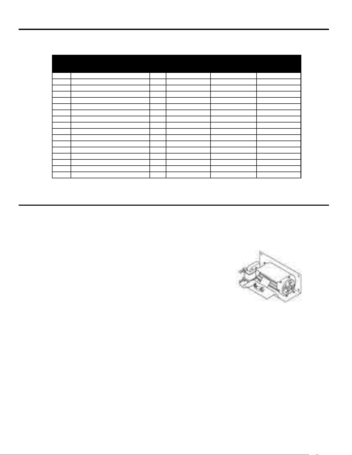
ACCESSORIES
127,&($OODFFHVVRULHVPD\QRWEHDYDLODEOHIRUDOO¿UHSODFHPRGHOV
7+(50267$7&21752//('%/2:(5.,7*)%)RUDOOPRGHOV Provides better heat
GLVWULEXWLRQ0DNHV¿UHSODFHPRUHHႈFLHQW$XWRPDWLFDOO\WXUQVRႇDQGRQDVQHHGHG
ITEM
No.
DESCRIPTION QTY
PART NUMBER
9))3+' 9))3+' 9))3+'5
1 Log Set (Complete) 1 700-S1018 700-M1018 700-L1018
1-1 Log 1 1 700-S1018-01 700-M1018-01 700-L1018-01
1-2 Log 2 1 700-S1018-02 700-M1018-02 700-M1018-02
1-3 Log 3 1 700-S1018-03 700-M1018-03 700-M1018-03
1-4 Log 4 1 700-S1018-04 700-M1018-04 700-M1018-04
1-5 Log 5 1 700-S1018-05 700-M1018-05 700-M1018-05
2 Burner Assembly (Complete) 1 700-S2000 700-M2000 700-L2000
2-1 ODS Pilot - NG 1 GZ20-30B GZ20-30B GZ20-30B
2-2 ODS Pilot - LP 1 GZ20-29B GZ20-29B GZ20-29B
2-3 Selector Knob 1 GZ20-17 GZ20-17 GZ20-17
2-4 Regulator, (NG) Natural Gas 5" W.C. 1 GR-130B2-GHP GR-130B-GHP GR-130B8-GHP
2-5 Regulator, (LP) Liquid Propane 10" W.C. 1 GR-130A2-GHP GR-130A-GHP GR-130A8-GHP
2-6 Ignitor Module 1 GZ20-32a GZ20-32a GZ20-32a
3 Remote Receiver 1 N/A N/A 80-05-102
4 Thermostat Remote 1 N/A N/A 80-05-101
2-7 Control Valve, EUROSIT 360 1 0630560 0630560 N/A
2-8 Control Valve 1 N/A N/A AF-1110
REPLACEMENT PARTS LIST
42
33
This limited warranty is extended to the original retail purchaser of this heater and warrants against any
2
2
two
two
years
years
43
34
GHP Group, Inc.
6440 W Howard S t
Niles, IL 60714-3302
Tel: (877) 447-4768
www.ghpgroupinc.com
GHP Group, Inc.
6440 W Howard St
Niles, IL 60714-3302