Loading ...
Loading ...
Loading ...
City Series CC40E-11 | 59
installation
C
L
C
L
56-1/4" (1429mm)
Min. height
(Rigid)
center
of hole
Diagram 4
Diagram 3
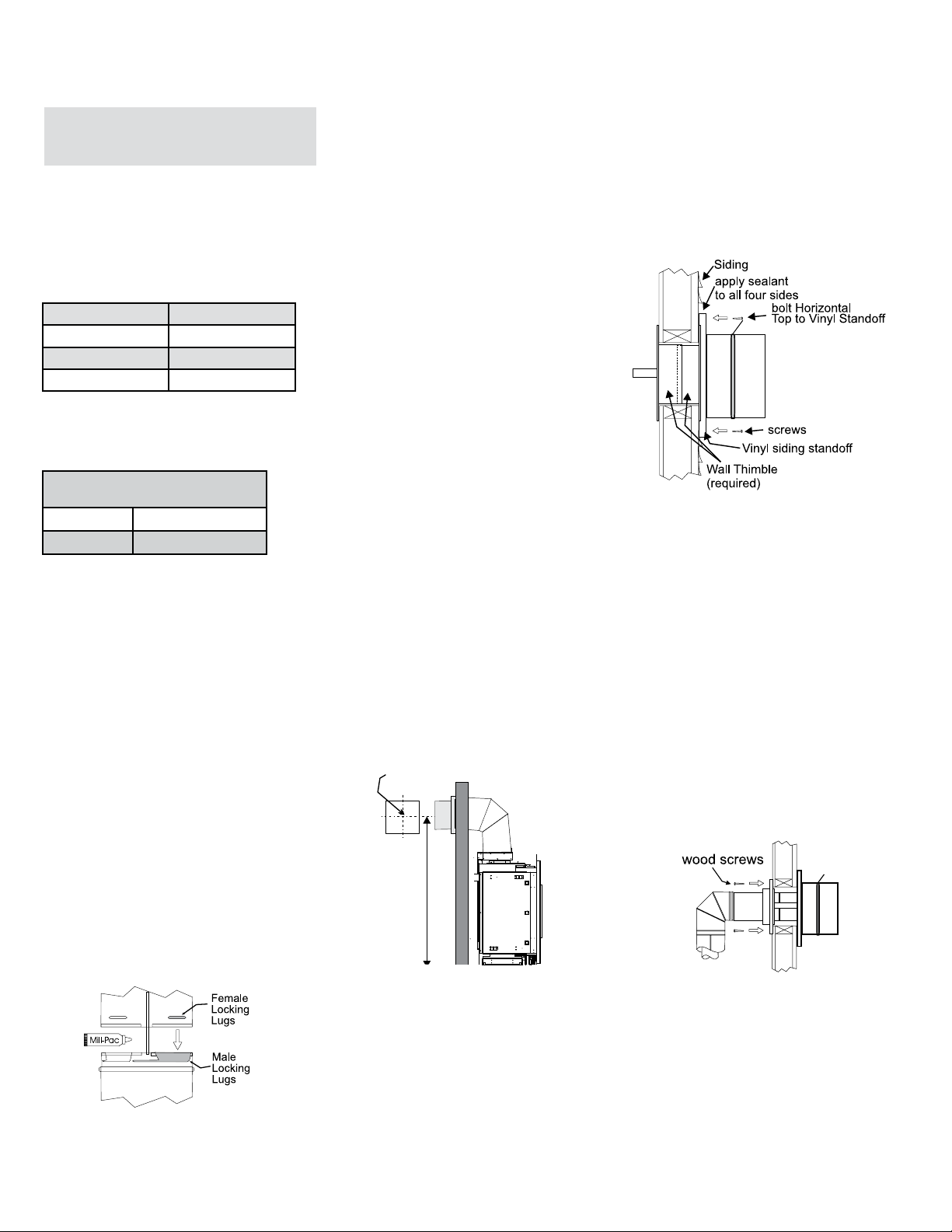
7. Ensure that the pipe clearances to combustible
materials are maintained (Diagram 3). Install
the termination cap.
Note: If installing termination on a vinyl
siding covered wall, a vinyl siding
standoff or furring strips must be
used to ensure that the termination
is not recessed into the siding.
The four wood screws provided should be
replaced with appropriate fasteners for stucco,
brick, concrete, or other types of sidings.
8. Before connecting the horizontal run of vent pipe
to the vent termination, slide the Wall Thimble
over the vent pipe. The wall thimble is required
for all horizontal terminations.
9. Slide the appliance and vent assembly towards
the wall carefully inserting the vent pipe into the
vent cap assembly. It is important that the vent
pipe extends into the vent cap sufficient distance
so as to result in a minimum pipe overlap of
1-1/4 inches (32mm). Secure the connection
between the vent pipe and the vent cap.
10. Install wall thimble in the center of the framed
hole and attach with wood screws (Diagram 4).
Install the vent system according to the manufacturer's
instructions included with the components.
1. Set the unit in its desired location. Check to
determine if wall studs or roof rafters are in the
way when the venting system is attached. If this
is the case, you may want to adjust the location
of the unit. Rough in the gas preferably on the
right side of the unit and the electrical (junction
block is on the left side) on the left.
2. Direct Vent pipe and fittings are designed with
special twist-lock connections to connect the
venting system to the appliance flue outlet. A
twist-lock appliance adaptor is required.
3. In conjunction with the Approved Vent system,
install the adaptor after the unit is set in its
desired location. Put a bead of Mill-Pac inside
the outer section of the adapter and a bead of
Mill-Pac on the inner collar. Slip the adapter over
the existing inner and outer flue collar. Fasten to
the outer collar only with the 3 supplied screws
(drilling pilot holes will make this easier).
4. Level the fireplace and fasten it to the framing
using nails or screws through the top and side
nailing strips.
Diagram 1
Note: For best results and optimum
performance with each approved
venting system, it is highly
recommended to apply Mill-Pac
sealant (supplied) to every inner
pipe connection. Failure to do
so may result in drafting or
performance issues not covered
under warranty.
Diagram 2
Horizontal runs of vent must be supported every
3 feet (0.9meter). Wall straps are available for
this purpose.
6. Mark the wall for a square hole.-see chart to left
for size. The center of the square hole should line
up with the center-line of the horizontal pipe. Cut
and frame the square hole in the exterior wall
where the vent will be terminated. See diagram
2 for center line requirements.
If the wall being penetrated is constructed of
non-combustible material, i.e. masonry block
or concrete, an 8" (203mm) diameter hole is
acceptable.
Note:
a) The horizontal run of vent must be level, or
have a 1/4 inch rise for every 1 foot of run
towards the termination. Never allow the
vent to run downward. This could cause
high temperatures and may present the
possibility of a fire.
b) The location of the horizontal vent
termination on an exterior wall must meet
all local and national building codes.
5. Assemble the desired combination of pipe and
elbows to the appliance adaptor and twist-lock
for a solid connection.
Recommended Framed Opening
Size
Vent Size Framing Size
4" x 6 - 5/8" 10" x 10"
Horizontal Top 3" (76mm)
Horizontal Side 2 " (51mm)
Horizontal Bottom 2" (51mm)
Vertical Vent 2" (51mm)
Minimum Vent Clearances
to Combustibles
Horizontal Termination - 4" x
6-5/8" Venting (Rigid Vent Sys-
tems)
Below are the recommended framing dimensions
(inside measurements) for the 4" x 6-5/8" rigid
vent terminations - for use with a firestop or wall
thimble.
Clearances noted below must be maintained; except
when passing through a wall, ceiling or at the termination
where the use of a firestop or wall thimble reduces
clearance to 1-1/2" (38mm).
Loading ...
Loading ...
Loading ...