Loading ...
Loading ...
Loading ...
PREPARATIONS ➤ c Connecting playback devices En 23
Connect video devices such as BD/DVD players, set-top boxes (STBs) and game consoles to the unit. Depending on the video/audio output jacks available on your video device,
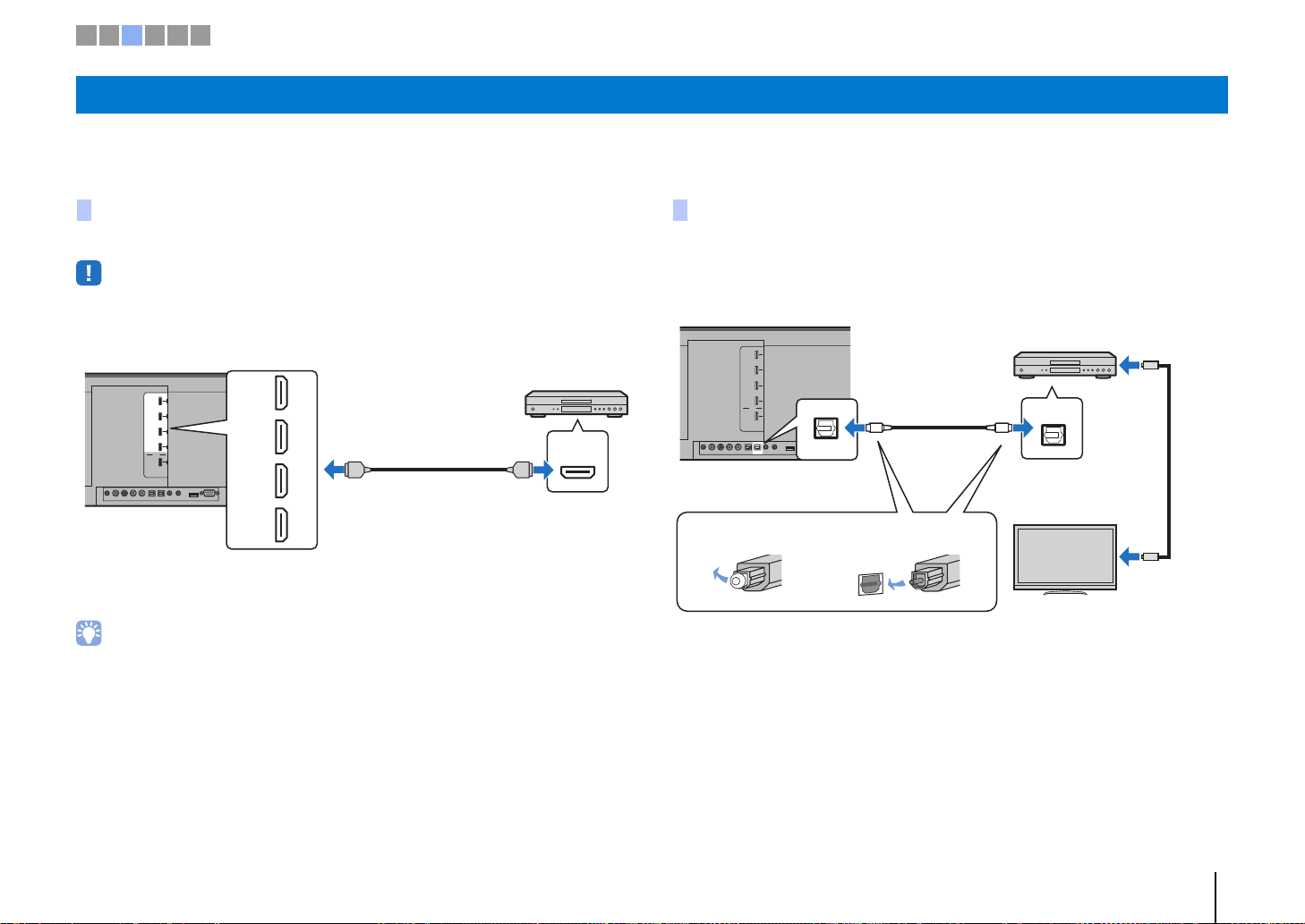
choose one of the following connections. We recommend using an HDMI connection if the video device has an HDMI output jack.
Connect a video device to the unit with an HDMI cable (not supplied).
• This unit supports HDCP version 2.2, a copy protection technology. When using an HDCP 2.2-compliant
playback device, such as a set-top box, connect it to the unit via the HDMI IN 1 jack. When connecting
playback devices that do not support HDCP version 2.2, any HDMI IN jack (1–4) may be used.
The audio/video played on the video device will be output though the unit by switching
input to HDMI 1–4 using the HDMI 1–4 key on the remote control.
• Once the HDMI control function has been activated (p. 35), video and audio content from playback devices
can be output from the TV even when this unit is off (HDMI signal pass-through).
• Use a 19-pin HDMI cable with the HDMI logo printed on it. A cable with a maximum length of 5 m is
recommended to prevent degradation of signal quality.
• For playback of 3D and 4K video content, use a high-speed HDMI cable.
• When audio from the video device cannot be output via the HDMI jack, use an optical cable to connect the
video device to the unit via the digital optical output jack on the video device and the OPTICAL jack on the
unit. If the video device is connected to the unit in this way, change “Audio Assign” to “Optical” in option
menu (p. 85).
Connect a video device to this unit via the optical cable. Next, connect the video
device’s video output to the TV’s video input.
The audio played on the video device will be output though the unit by switching input
to OPTICAL using the OPTICAL key on the remote control.
c Connecting playback devices
HDMI connection
SYSTEM
CONNCETOR
RL
AUX1
AUX2 TV OPTICAL IR-IN
IN 1
(HDCP2.2)
IN 2
IN 3
IN 4
OUT
(ARC)
HDMI
IR-OUT
UPDATE ONLY
RS-232C
NETWORK
SUBWOOFER
OUT
HDMI
IN 1
(HDCP2.2)
IN 2
IN 3
IN 4
HDMI HDMI
The unit (rear)
HDMI IN 1–4 jacks
HDMI output
Video device
Optical connection
SYSTEM
CONNCETOR
TV
IN 1
(HDCP2.2)
IN 2
IN 3
IN 4
OUT
(ARC)
HDMI
IR-IN IR-OUT
UPDATE ONLY
RS-232C
NETWORK
SUBWOOFER
OUT
RL
AUX1
AUX2 OPTICAL
OPTICAL
OPTICAL
OO
The unit (rear)
OPTICAL jack
Audio output
(digital optical)
1. Remove the cap 2. Check the direction of
the plug
Video device
TV
To video output
jack
To video input
jack
1 2 3 4 5 6
Loading ...
Loading ...
Loading ...