Loading ...
Loading ...
Loading ...
2 ELEVATION HANDWHEEL...elevates or lowers the
blade_ Turn clockwise to elevate, counterclockwise
to lower.
NOTE: Any t_me sawblade has been etevated to 2-
5!8 inches or h_gher above the table _ w_Ii be neces-
sary to _ower the btade by turn_ng me elevation
handvtC_eel 5 turns counterclockwise before tilting to
bevel
3 TILT HANDVtt'HEEL.,tilts the blade for bevel cut-.
t_ng Turn clOCkwise to tilt toward tuft_ .counterclock-
wise to titt toward vertical.
When the blade iS tilted to me LEFT as far as _t w_II
go. _t should be at 45 degrees to the table and T.ne
beve_ indicator should point 45 degrees,
NOTE: There are LIMIT STOPS on the saw whsch
prevent the blade from tilting beyond 45 degrees to
the LEFT and 90 degrees to the RIGHT, (See
"Adjustment" section "Blade Tilt, or Squareness of
B_ade to Table'1.
4 TILT LOCK HANDLE., ,locks the blade in the
desired tilt position. To loosen, turn counterclock-
wise. Push handle in and turn it to another position if
necessary in order to tighten or loosen.
IMPORTANT: Be sure handle is hanging in the
"DOWfN" position before tilting blade. If it is
pointing to the 1 o'clock position it may jam on
underside of the table and bend the locking bolt.
5 RtP FENCE,.,Is locked in place by pushing the lock
lever down until the lever rests on the stop. To move
the fence, lift the lock lever and grasp the fence with
one hand at the front and then push fence left or
r_ght.
Slots are provided in the nD fence for altachmg a
wood facing when uslng the da.do heac or molding
head, featherboards or other l_gs and fixtures
Select a piece of smooth stratght wood approx. 3/4.
n. thick and the same length as the rip fence,
To fasten auxiliary face to the fence use 3 eacn,
t/4"-20 x 3/4" square head machine screws with
nuts, Counterbore 1" dta. hole 3/8" deep into the 3/4"
board at the designated dimensions,
CHANNEL FENCE
See Fig A. _4-AUX.FACE
t.,4_ HOLE JI"_L' I_J-'-_z_
Drill a 1/4"
I* X 3 8" DEEP
clearance hote _ _11[WtJ;,t-, SOUARENEAP
through the board. HE×_UT";_t JJ_ BOLT
_,.'.=o ' L-I
1" COUNTERBORE, WASHER
318_'DEEP 1'4"x ss*x 1;1_°
114= CLEARANCE ........... 34"
.....................
....... 18"
HOLE THROUGH i.6-.:
THE BOARD, WOODFACtNG
.... 3/40
............. 18" -................
........ 34 ...................... '
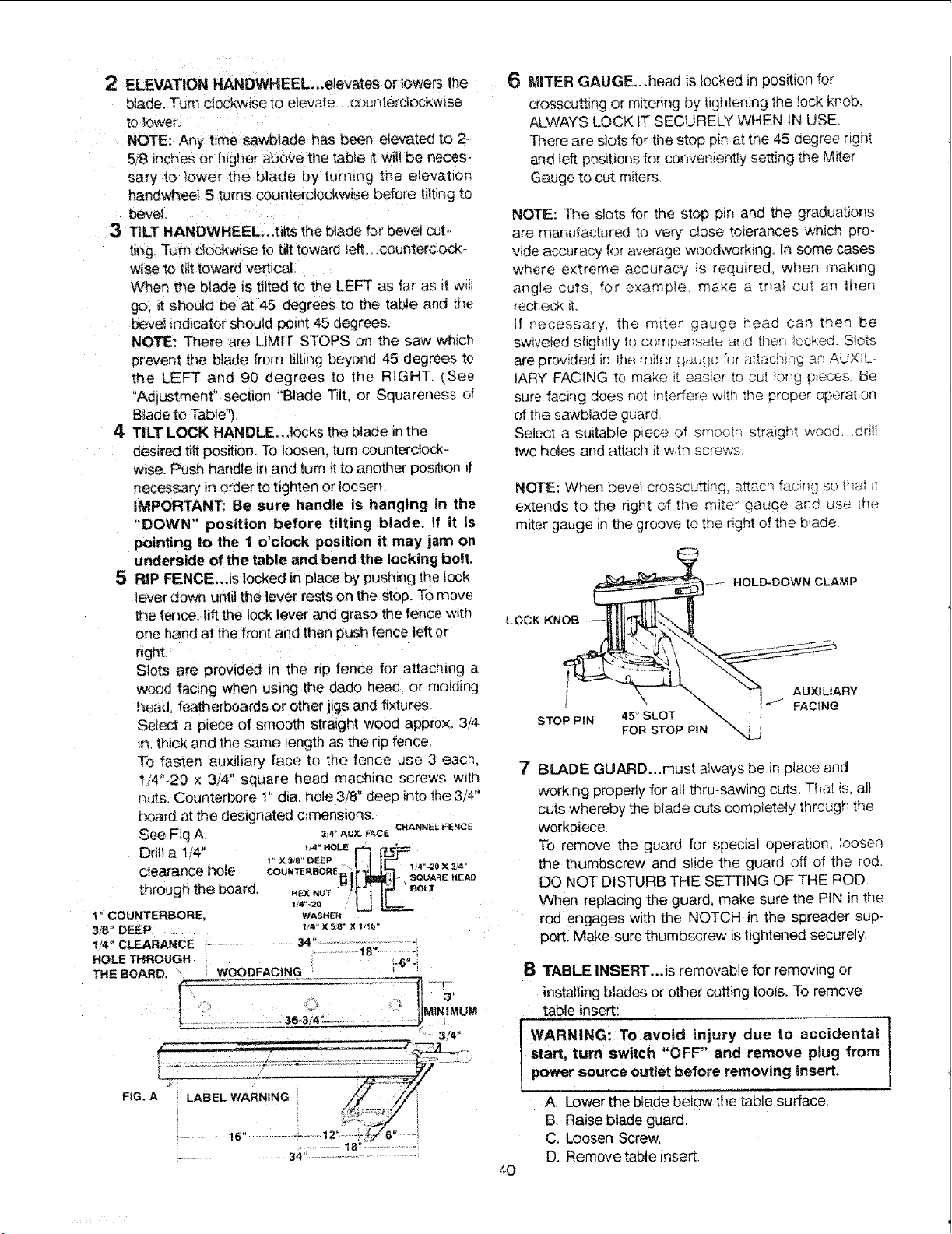
6 MITER GAUGE_.head is locked _nposition for
crosscut£ng or mitenng by t_ghteningthe !ock knob.
ALWAYS LOCK tT SECURELY WHEN IN USE.
There are slots for the stop p_nat the 45 degree right
and tuft pos_bonsfor conveniently setting the M_ter
Gauge to cut m_ters
NOTE: The slots for the stop p_n and the graduabons
are rnanufactured to very c_ose tolerances wn;cn pro-
vide accurNcy for average woodworking, in some cases
where extreme accuracy _s required when making
angle cuts for example make a tr_a_ cut an then
recheck _1.
If necessary, me m_ter gauge head can men be
swweied s!_ghtly to compensate ar;d men .ockea Slots
are provided in the m_ter qauqe for a_achin_ ar AUXIL-
IARY FAC!NG to make _, eas_er to cut _ong D_eces Be
sure facing does ncI ffqterfere wqn the orooer operation
of the sawb_ade guard
Select a suitable piece of srnocu straign_ wona. dnlt
two ho_es arid attach it w;th _crews
NOTE: When bevel crosscusing, attach fac.[_g s ___'_;T it
extends to the right of the m_ter gauge anc. use the
miter gauge m the groove to tne nght of the b!ade.
_.- HOLD-DOWN CLAMP
!__UXILIARY
; ..o_,_. _ -- I t.,.J FACING
STOP P_N 45_SLOT -_.
FOR STOP PIN "-
8 TABLE INSERT...Is removable for removing or
installing blades or other cutting tools. To remove
table insert:
WARNING: To avoid injury due to accidental
start, turn switch "OFF" and remove plug from
power source outlet before removing insert.
A Lower the blade below the table surface.
B. Raise blade guard.
C, Loosen Screw,
D. Remove table inset,
7
BLADE GUARD...must atways be in place and
working properly for aHthru-sawing cuts, That is, all
cuts whereby the blade cuts completely through the
workpiece,
To remove the guard for special operation, loosen
the thumbscrew and slide the guard off of the rod.
DO NOT DISTURB THE SETTING OF THE ROD.
When replacing the guard, make sure the PIN in the
rod engages with the NOTCH in the spreader sup-
portl Make sure thumbscrew is tightened securely.
40
Loading ...
Loading ...
Loading ...