Loading ...
Loading ...
Loading ...
MOUNTING SWITCH
1. From among the loose parts find the following hard-
ware:
1 Switch Assembly with Bracket
2 Pan Head Screws 10-32 x 3/8" long
2 Lockwashers - 3/16" I.D,
2 Square Nuts - 10-32
6 Pan HD ScrewTy "T" 10-32 x3/8
2 Plastic End Caps
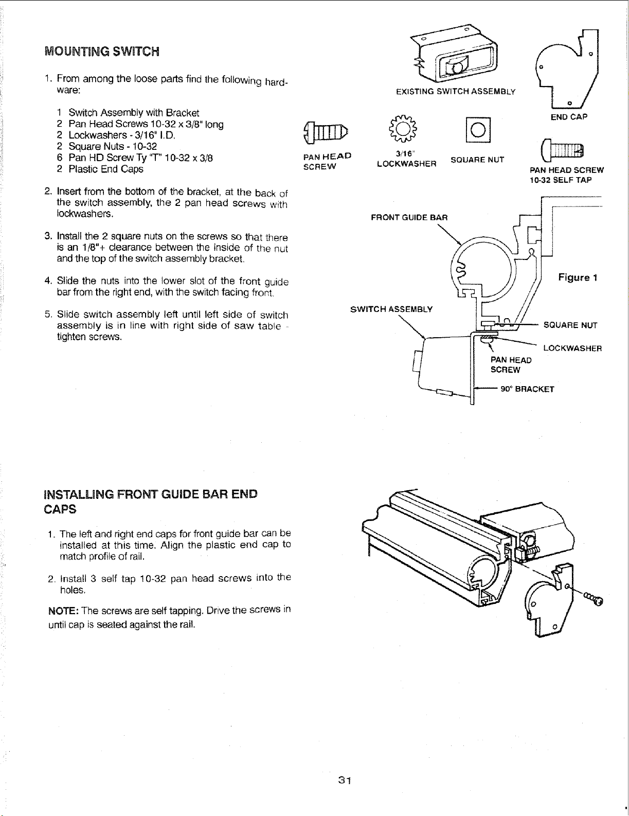
2. Insert from the bottom of the bracket, at the back of
the switch assembly, the 2 pan head screws with
tockwashers.
3. Install the 2 square nuts on the screws so that there
is an 1/8"+ clearance between the inside of the nut
and the top of the switch assembly bracket,
4. Slide the nuts into the lower slot of the front guide
bar from the right end, with the switch facing front,
5. Slide switch assembly left until left side of switch
assembly is in line with right side of saw table
tighten screws.
PAN HEAD
SCREW
EXISTING SWITCH ASSEMBLY
_ END CAP
3/16"
LOCKWASHER SQUARENUT
PAN HEAD SCREW
10-32SELFTAP
[
FRONT GUIDE BAR
SWITCH ASSEMBI_
SQUARE NUT
II' N
__j_ 9o ° BRACKET
INSTALMNG FRONT GUIDE BAR END
CAPS
1. The left and right end caps for front guide bar can be
installed at this time. Align the plastic end cap to
match profile of rail.
2. Install 3 self tap 10-32 pan head screws into the
holes,
NOTE: The screws are self tapping, Drive the screws in
until cap is seated against the rail,
31
Loading ...
Loading ...
Loading ...