Loading ...
Loading ...
Loading ...
3 instanttheotherrackfromtherightendina similar
mannerasdescribedin #2.slidingrackagainstleft
rack.Tightenattscrews.
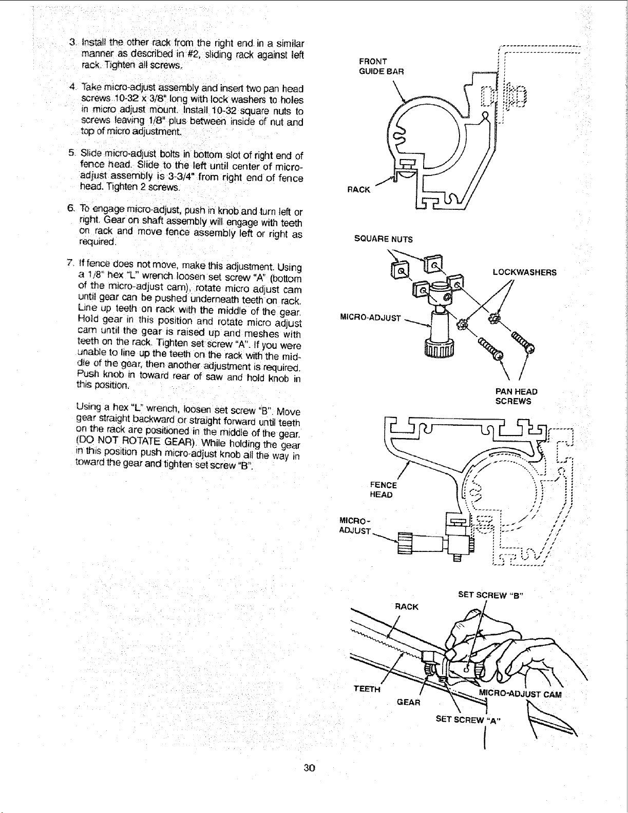
4 _akemicro-adjustassemblyandinserttwopanhead
screws10-32x 3/8"longwithlockwashersto holes
mm,,croadjustmount.Install10-32squarenutsto
screwsleaving1/8"plusbetweeninsideof nutand
topofmicroadjustmenL
5. Slidemicro-adjustboltsinbottomslotofrightendof
fencehead.Slideto theleftuntilcenterof micro-
adjustassemblyis 3-3/4"fromrightendof fence
head.Tighten2 screws.
6. Toengagemicro-adjust,pushinknobandturnleftor
right.Gearonshaftassemblywillengagewithteeth
on rackandmovefenceassemblyleftor rightas
required.
7 fffencedoesnotmove,makethisadjustment.Using
a 1/8"hex"L" wrench loosen set screw "A" (bottom
of the m_cro-adjust cam), rotate micro aGjust cam
until gear can be pushed underneath teeth on rack.
Line up teeth on rack w_th the middle of the gear.
Ho_d gear in this position and rotate micro ad ust
cam until the gear is raised up and meshes with
t_th on me rack. Tighten set screw "A". If you were
unable to line up the teeth on the rack with the mi@
die of me gear, then another adjuslment _srequired.
Push knob tn toward rear of saw and hold knob in
this pos_t_on.
Using a hex "L" wrench, loosen set screw "B" Move
gear straight backward or straight forward until teeth
on _e rack are positioned in the middle of the gear.
(DO NOT ROTATE GEAR). While holding the gear
{nthis POSrltonpush micro_adjust knob all the way _n
toward the gear and tighten set screw "B".
FRONT
GUIDE BAR
\
RACK
SQUARE NUTS
CRO-ADJUST
FENCE
HEAD
MICRo-
ADJUST
2i
LOCKWASHERS
PAN HEAD
SCREWS
RACK
SET SCREW "B"
TEETH
GEAR
MICRO-ADJUST CAM
SET SCREW "A"
I
30
Loading ...
Loading ...
Loading ...