Loading ...
Loading ...
Loading ...

AGRAS MG-1P SERIES User Manual
© 2018 DJI All Rights Reserved.
13
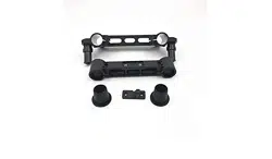
4. Insert the plugs on the left landing gear leg into the mounting holes on the spray tank.
5. Slide the xing bracket on the right landing gear leg to the marks on the tubes to align the screw
holes on the xing bracket with the n on the right side of the spray tank. Tighten the two M3×12
screws and insert and tighten one M3×10 (Plus) screw.
6. Connect the two pump cables and one liquid level meter cable to their corresponding ports on
the aircraft body.
Unfolding the Frame Arms
1. Unfold the frame arms
1
and tighten the two arm sleeves at each of the junctions
2
.
2. Identify the position and rotational direction of the motors. The top view shows motors M1 to M8
arranged in a counter-clockwise order, with motors M1 and M2 at the front of the aircraft, and
motors M5 and M6 at the rear. Motors M1, M3, M5, and M7 rotate counter-clockwise as indicated
by the “CCW” mark, while motors M2, M4, M6, and M8 rotate clockwise as indicated by the “CW”
mark.
M3×12M3×12
M3×10 (Plus)
Marks
M1M2
M3
M4
M5 M6
M7
M8
Loading ...
Loading ...
Loading ...