Loading ...
Loading ...
Loading ...

31
Delivered Parts and Dimensions
Standard Delivery
Item Count Part Name
1.11 2 Sensor module cable 15 cm/6 in (installed in camera)
1.12 1 I/O cable with red clips to front element 15 cm/6 in (installed)
1.13 1 Hinged ferrite for Ethernet cable (installed)
1.14 1 Hinged ferrite for sensor module cable (installed)
1.15 2 Rubber plug for covering mounting screws, white
1.16 3 Stainless steel Allen screw M6x30 (installed)
1.17 3 Stainless steel washer Ø 6.4 mm (installed)
1.18 1 Stainless steel spring washer Ø 6.4 mm (wall/ceiling mt., inst.)
1.19 1 Stainless steel lock nut M6 (wall/ceiling mount, installed)
1.20 1 Rubber plug, black (installed)
Mounting Supplies
M.1 4 Stainless steel washer Ø 6.4 mm
M.2 4 Dowels 8 mm
M.3 4 Stainless steel wood screw with hex head 6x50 mm
M.4 1 Allen wrench 2.5 mm
M.5 1 Allen wrench 5 mm
M.6 1 Lens wrench (B016 lens, glass/lter insert, dome)
M.7 1 Module key (sensor module, focusing of lenses)
M.8 1 Rubber sealing for wall/ceiling mount, white
M.9 1 Ceiling mount for VarioFlex mount
M.10 4 Protection cover for screw, white
M.11 4 Security clip for sensor or blind modules, red
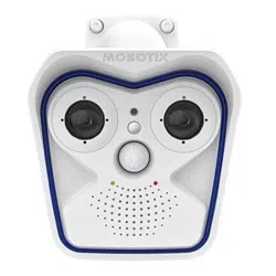
Design of the MOBOTIX M16
The Base module of the MOBOTIX M16 consists of the camera housing with VarioFlex mount
(wall or ceiling) and the front element.
1
2
L
Key
LEDs
Sensor modules
VarioFlexWallMount
Microphone
Ext.temperaturesensor
PIR sensor
Camera housing
LED default settings
1 Power (an),
Error (ashes)
2 Recording (ashes)
To press the key, use a
paper clip for example,
but never use sharp
or pointed objects!
Loading ...
Loading ...
Loading ...