Loading ...
Loading ...
Loading ...
Pulse and Pulse-trains
Pulse-Train Set-up10
The baseline is the signal level between the end of one pulse and the start of the next, i.e.
it is the level at which all pulses start and finish. The baseline can be set between -5·0 V
and +5·0 V by direct numeric keypad entries or by using the rotary control.
Note that the actual baseline level at the output will only be as set in this field if the
output amplitude is set to maximum (10 V p-p into 50 Ω) on the AMPLITUDE screen
and terminated in 50 Ω. The amplitude control scales the baseline setting, so that if, for
example, the amplitude were set to 5 V p-p into 50 Ω then the actual baseline range
would be -2·5 V to +2·5 V for set values of -5·0 V to +5·0 V.
Note also that the output levels are doubled when the output is not terminated.
Pressing next on this screen calls the first of 3 screens for the first pulse in the pattern:
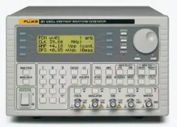
Pulse 1 level
+5·000 V
done next
The pulse level can be set on this screen between -5·0 V and +5·0 V by direct numeric
keypad entries or by using the rotary control. As with the baseline level described above
the set pulse levels are only output if the amplitude setting is set to maximum (10 V p-p
into 50 Ω) on the AMPLITUDE screen and terminated in 50 Ω. Adjusting the amplitude
scales both the peak pulse levels and the baseline together, thus keeping the pulse shape
in proportion as the amplitude is changed, exactly as for arb waveforms.
Note also that the output levels are doubled when the output is not terminated.
By pressing the Pulse soft-key on this (and subsequent) screens, the pulse to be edited
can be directly selected using the numeric keypad or the rotary control. This is useful for
editing a particular pulse in a long pulse train without needing to step through all the
earlier pulses.
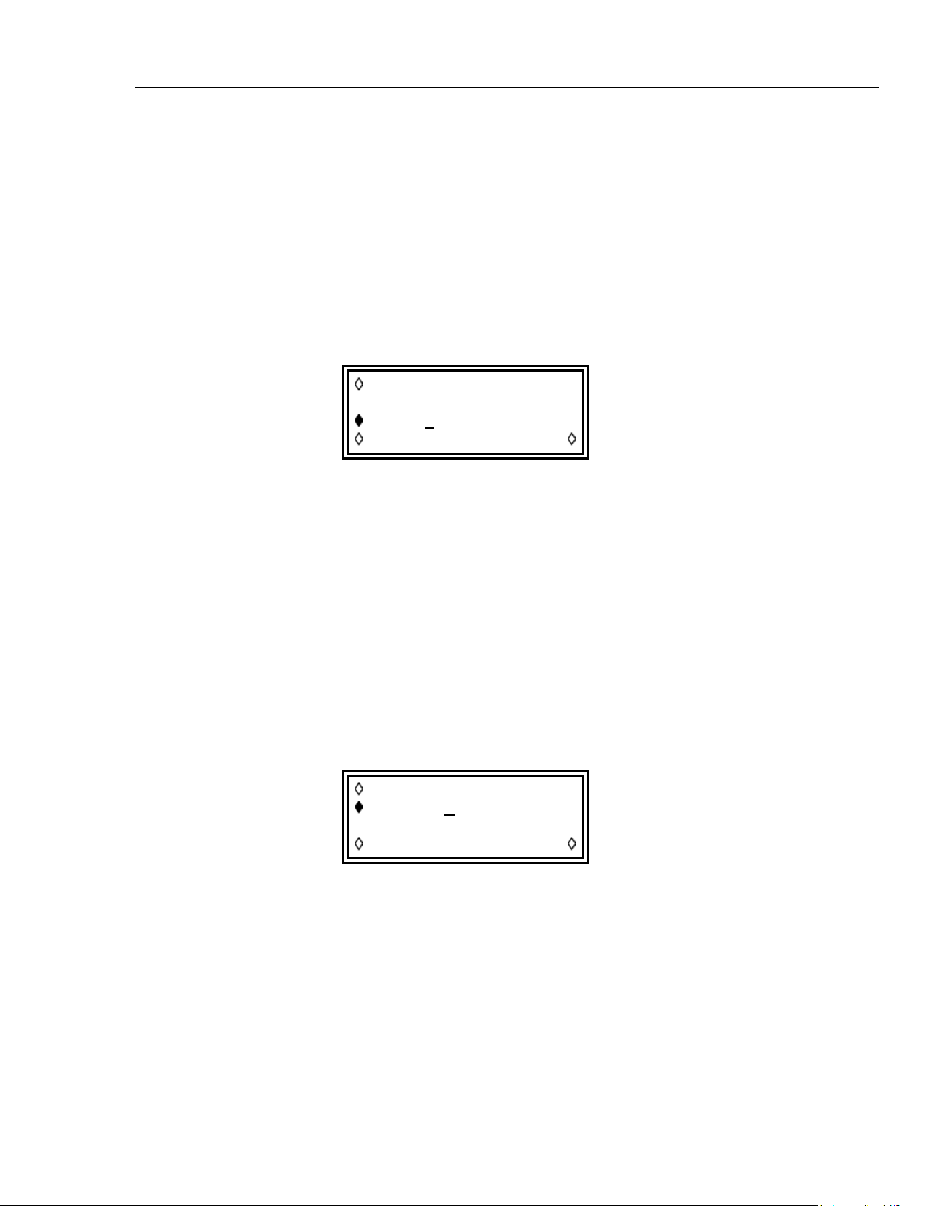
Pressing next then calls the pulse width screen for the first pulse:
Pulse 1 width
program 25·00 us
(actual 25·00 us)
done next
The width can be entered directly from the numeric keypad or by using the rotary control.
Any value in the range 25.00 ns to 99·99 s can be programmed but the actual value
may differ; for this reason the actual pulse width is shown below the program
width. The variation between program and actual will only really be noticeable
for very short pulse-train periods (only a few points in the pulse-train) and very long
periods (each of the 50,000 points has a long dwell time) for exactly the same reasons as
described in the Pulse Set-up section.
Pressing next calls the pulse delay screen for the first pulse:
10-5
1.888.610.7664 sales@GlobalTestSupply.com
Fluke-Direct.com
Loading ...
Loading ...
Loading ...