Loading ...
Loading ...
Loading ...
Appendix A
Mains Operating Voltage
Mains Operating Voltage
Before connecting the instrument to an ac outlet, check that the instrument operating
voltage marked on the rear panel is correct for the local supply.
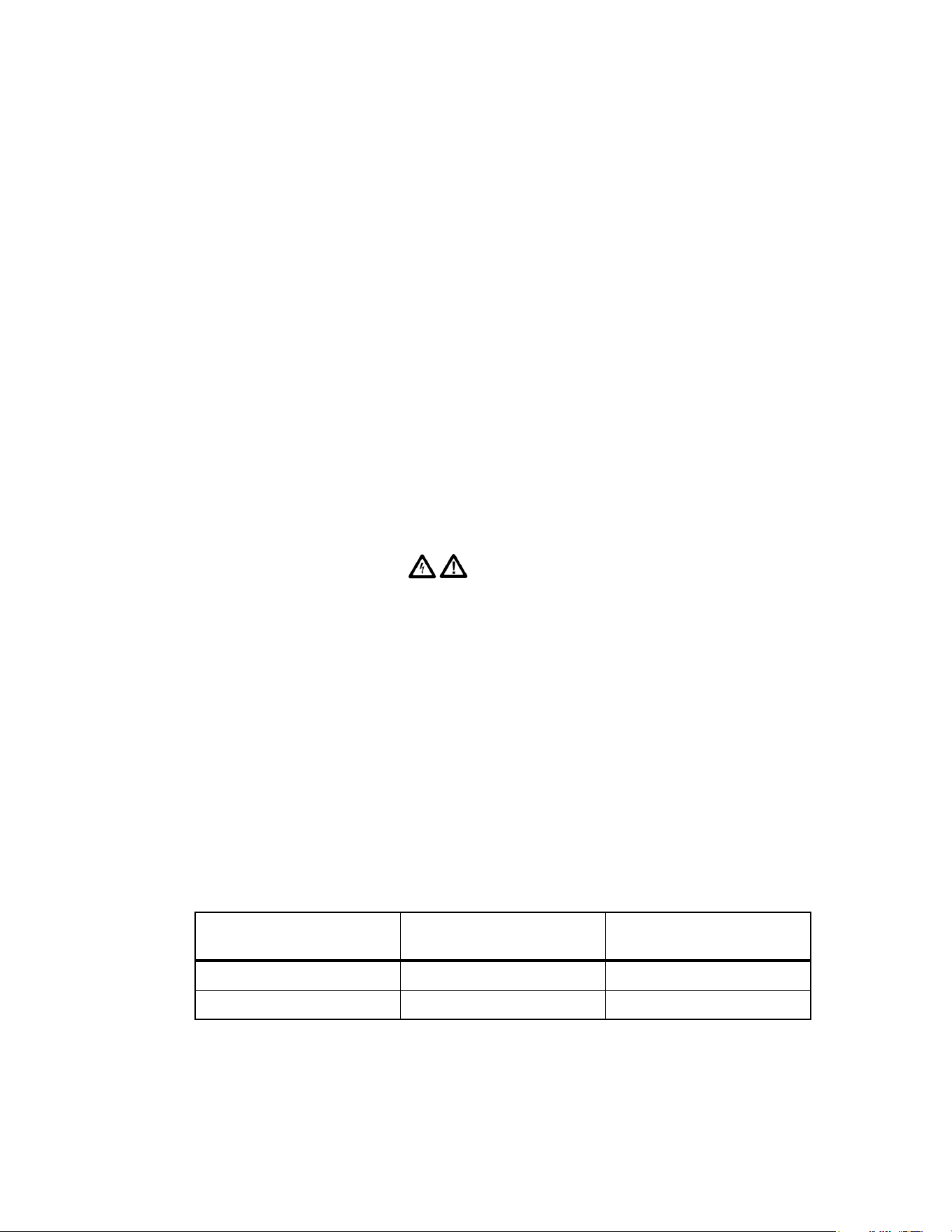
Warning
To avoid the possibility of electric shock, always ensure the
instrument is disconnected from the ac supply before opening
the case.
If it is necessary to change the operating voltage, proceed as follows:
1. Disconnect the instrument from all voltage sources.
2. Remove the screws which retain the top cover and lift off the cover.
3. Change the transformer connections following the appropriate diagrams below.
4. Refit the cover and the secure with the same screws.
5. To comply with safety standard requirements the operating voltage marked on the
rear panel must be changed to clearly show the new voltage setting.
6. Change the fuse to one of the correct rating according to the table below:
Table 1-1. Approved Fuse Types
Single-channel
model 281
Two- and Four-channel
models 282/284
For 230 V operation 250 mA (T) 250 V HRC 1 A (T) 250 V HRC
For 100 V or 115 V operation 500 mA (T) 250 V HRC 2 A (T) 250 V HRC
To replace the fuse, disconnect the mains lead from the inlet socket and withdraw the
fuse drawer below the socket pins. Change the fuse and replace the drawer.
The use of makeshift fuses and the short-circuiting of the fuse holder are prohibited.
A-1
1.888.610.7664 sales@GlobalTestSupply.com
Fluke-Direct.com
Loading ...
Loading ...
Loading ...