Loading ...
Loading ...
Loading ...
Remote Operation
RS232 Interface16
RS232 Interface
RS232 Interface Connector
The 9-way D-type serial interface connector is located on the instrument rear panel. The
pin connections are as shown in chapter 3, Connections, table 3-1.
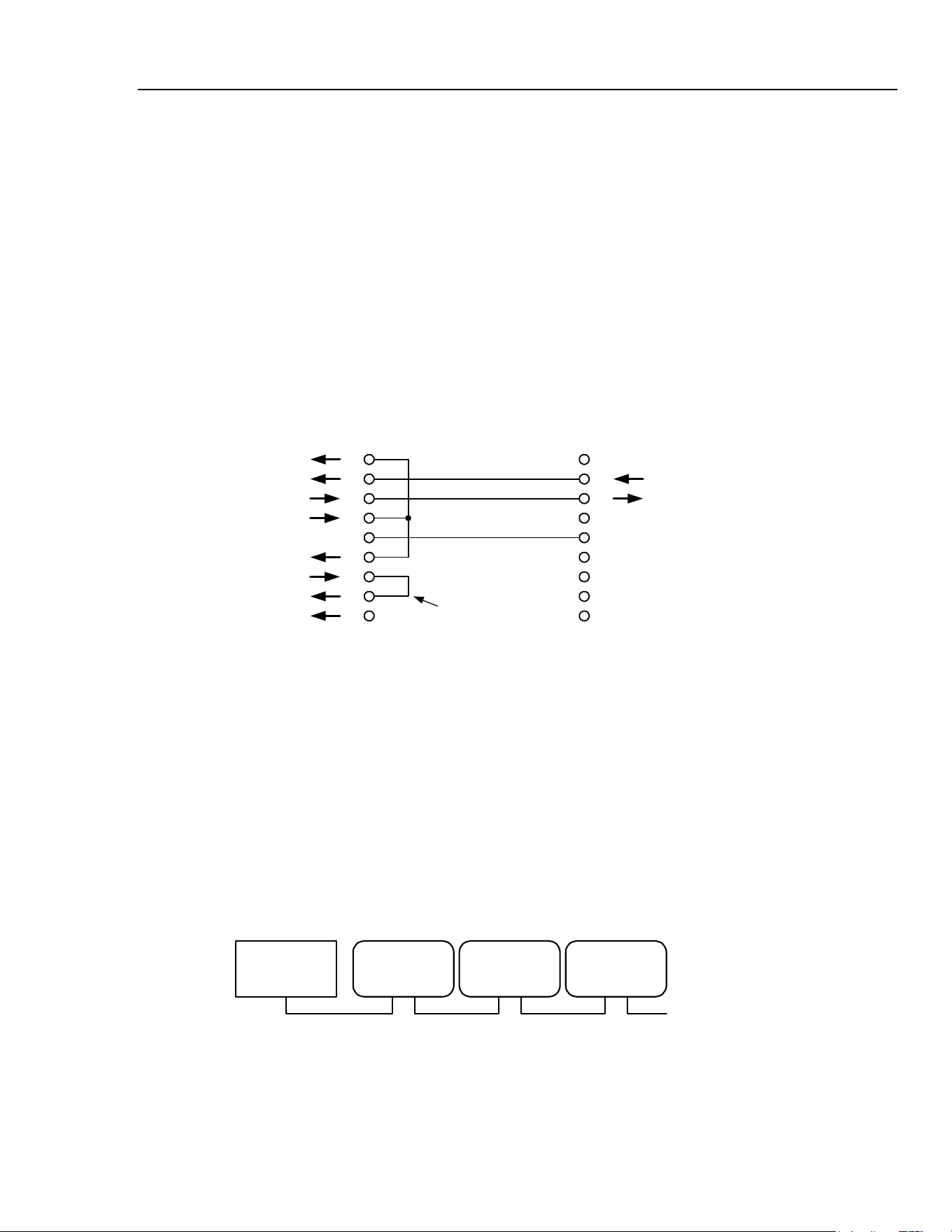
Single Instrument RS232 Connections
For single instrument remote control only pins 2, 3 and 5 are connected to the PC.
However, for correct operation links must be made in the connector at the PC end
between pins 1, 4 and 6 and between pins 7 and 8, as shown below. Pins 7 and 8 of the
instrument must not be connected to the PC. This means you should not use a fully wired
9–way cable.
1
2
3
4
5
6
7
8
9
1
2
3
4
5
6
7
8
9
DCD
RX
TX
DTR
GND
DSR
RTS
CTS
RI
RX
TX
GND
INSTRUMENT
9-WAY D
MALE
PC
9-WAY D
FEMALE
LINK TO
NULL OUT PC
shb0009f.emf
Figure 16-1. Single Instrument RS232 Connections
Baud Rate is set as described above; the other parameters are fixed as follows:
Start Bits: 1
Data Bits: 8
Parity: None
Stop Bits: 1
Addressable RS232 Connections
For addressable RS232 operation pins 7, 8 and 9 of the instrument connector are also
used.
Using a simple cable assembly you can make a 'daisy chain' connection system between
any number of instruments up to the maximum of 32, as shown below:
INSTRUMENT
1
INSTRUMENT
2
INSTRUMENT
3
CONTROLLER
TO NEXT
INSTRUMENT
shb0010f.emf
Figure 16-2. RS232 Daisy-Chained Instruments
16-3
1.888.610.7664 sales@GlobalTestSupply.com
Fluke-Direct.com
Loading ...
Loading ...
Loading ...