Loading ...
Loading ...
Loading ...
Standard Waveform Operation
Setting Generator Parameters 5
always show the entry in the most appropriate engineering units, in this case
12·34000 kHz.
With period selected instead of freq the frequency can be set in terms of a period,
for example 123·4µs can be entered as ·0001234 or 123·4 exp -6; again the display
will always show the entry in the most appropriate engineering units. Note that the
precision of a period entry is restricted to 6 digits; 7 digits are displayed but the least
significant is always zero. The hardware is programmed in terms of frequency, so that
when you make a period entry the synthesized frequency is the nearest equivalent value
that the frequency resolution and a 6-digit conversion calculation gives. If the frequency
is displayed after a period entry the value may differ from the expected value because of
these considerations. Further, once the setting has been displayed as a frequency,
converting back again to display period will give an exact 6-digit equivalent of the 7-digit
frequency, but this may differ from the period value originally entered.
Square waves, generated by clock synthesis, provides 4-digit resolution for both
frequency and period entry but the hardware is still programmed in terms of frequency
and the same differences may occur in switching the display from period to frequency
and back to period.
Turning the rotary control will increment or decrement the numeric value in steps
determined by the position of the edit cursor (flashing underline); the cursor is moved
with the left- and right-arrowed cursor keys.
Note that the upper frequency limits vary for the different waveform types; refer to the
Specifications section for details.
Frequency setting for arbitrary, sequence pulse and pulse-train is explained in the
relevant sections.
Amplitude
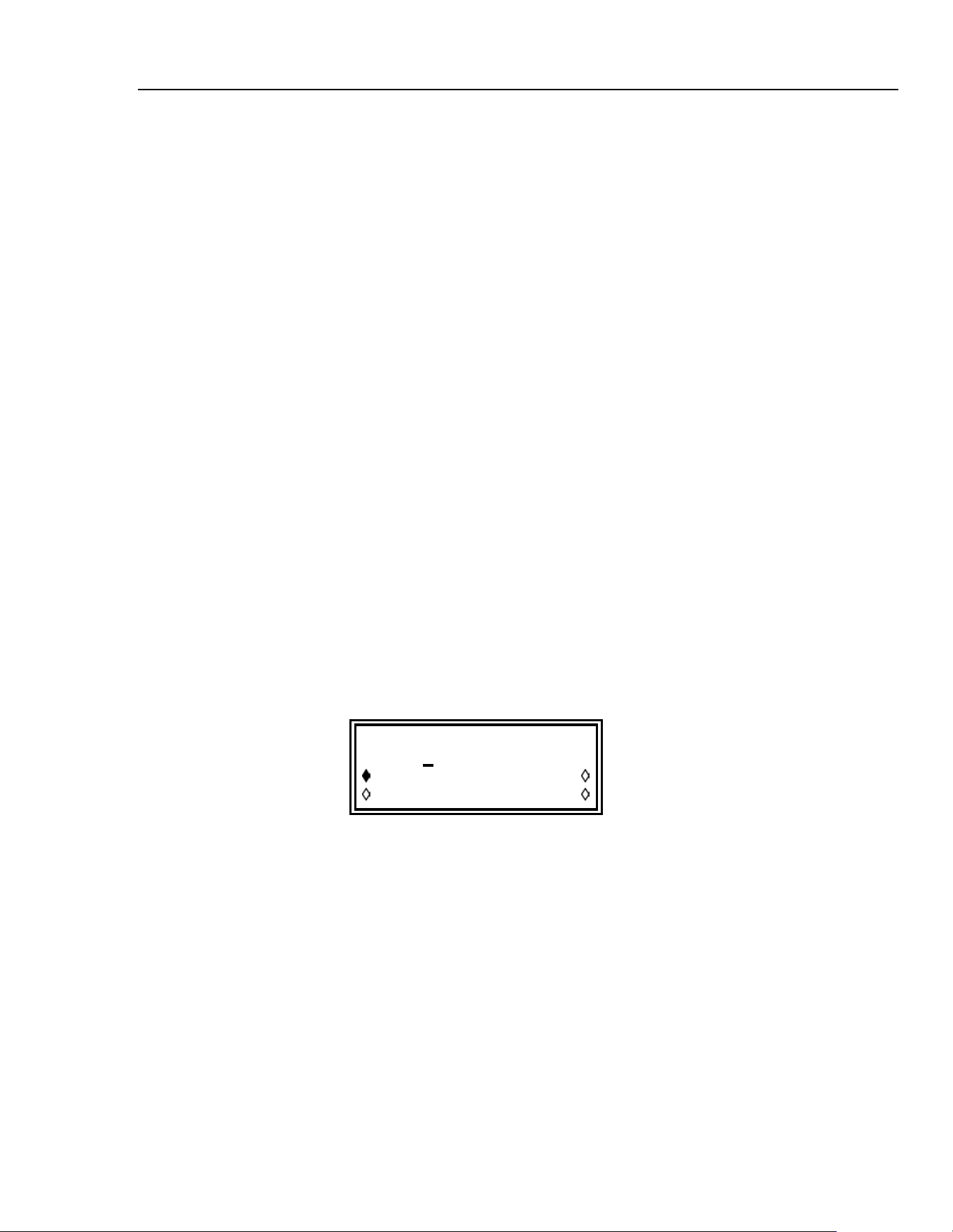
Pressing the AMPL key gives the AMPLITUDE screen:
AMPLITUDE:
+2
0.0 Vpp
Vpp Vrms
dBm load:hiZ
The waveform amplitude can be set in terms of peak-to-peak volts (Vpp), rms volts
(Vrms) or dBm (referenced to a 50 Ω or 600 Ω load). For Vpp and Vrms the level can be
set assuming that the output is open-circuit (load:hiZ) or terminated (load:50Ω or
load:600Ω); when dBm is selected termination is always assumed and the
load:hiZ setting is automatically changed to load:50Ω. Note that the actual
generator output impedance is always 50 Ω; the displayed amplitude values for 600 Ω
termination take this into account.
With the appropriate form of the amplitude selected (indicated by the filled diamond) the
amplitude can be entered directly from the keyboard in integer, floating point or
exponential format. For example 250 mV can be entered as ·250 exp -3 or 250, etc.
The display will always show the entry in the most appropriate engineering units, in this
case 250 mV.
Turning the rotary control will increment or decrement the numeric value in steps
determined by the position of the edit cursor (flashing underline); the cursor is moved
with the left- and right-arrowed cursor keys.
5-3
1.888.610.7664 sales@GlobalTestSupply.com
Fluke-Direct.com
Loading ...
Loading ...
Loading ...