Loading ...
Loading ...
Loading ...
281, 282, 284
Users Manual
As an output the logic levels are nominally 1 V and 4 V from typically 50 Ω.
REF CLOCK IN/OUT will withstand a short-circuit.
As an input the threshold is TTL/CMOS compatible.
Caution
To avoid risk of damage to the instrument, do not apply
external voltages exceeding ±10 V to this socket.
HOLD IN
HOLD IN controls the waveform hold function. The input impedance is nominally
10 kΩ.
Caution
To avoid risk of damage to the instrument, do not apply
external voltages exceeding ±10 V to this input.
CURSOR/MARKER OUT
The CURSOR/MARKER OUT socket provides an output pulse for use as a marker in
sweep mode or as a cursor in arbitrary waveform editing mode. It can be used to
modulate the Z-axis of an oscilloscope or can be displayed on a second oscilloscope
channel. The output impedance is nominally 600 Ω and the signal level is adjustable from
2 to14 V (nominal) from the cursor/marker menu on the UTILITY screen, as
described in chapter 14, System Operations from the Utility Menu.
Caution
To avoid risk of damage to the instrument, do not apply
external voltages to this output.
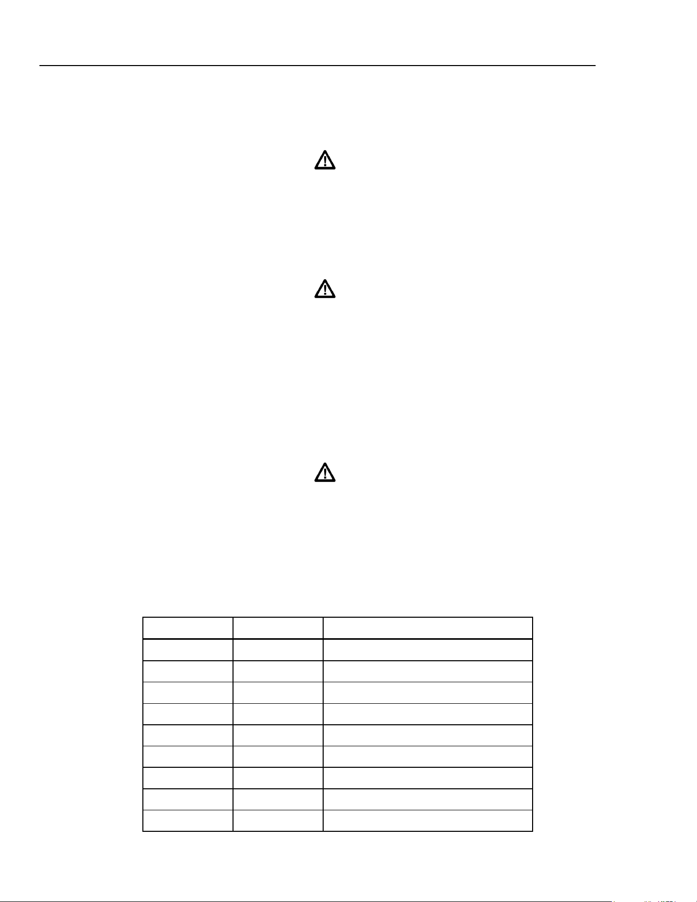
RS232
The RS232 interface is on a 9-pin D-connector and is compatible with addressable
RS232 use. The pin connections are shown below:
Table 3-1. RS232 Pin Functions
Pin number Signal name Description
1 - No internal connection
2 TXD Transmitted data from instrument
3 RXD Received data to instrument
4 - No internal connection
5 GND Signal ground
6 - No internal connection
7 RXD2 Secondary received data
8 TXD2 Secondary transmitted data
9 GND Signal ground
3-4
1.888.610.7664 sales@GlobalTestSupply.com
Fluke-Direct.com
Loading ...
Loading ...
Loading ...