Loading ...
Loading ...
Loading ...
Initial Operation
Principles of Operation 4
Thus for STANDARD FREQUENCY set to 1.000000 MHz rotating the control will
change the frequency in 1 kHz steps. The display will auto-range up or down as the
frequency is changed, provided that autoranging permits the increment size to be
maintained; this will in turn determine the lowest or highest setting that can be achieved
by turning the control. In the example above, the lowest frequency that can be set by
rotating the control is 1 kHz, shown on the display as 1
.000000 kHz.
This is the limit because to show a lower frequency the display would need to autorange
below 1 kHz to x
xx.xxx Hz, in which the most significant digit represents 100Hz, i.e.
the 1 kHz increment would be lost. If, however, the starting frequency had been set to
1.0000
00 MHz, i.e. a 100 Hz increment, the display would have autoranged at 1 kHz
to 9
00.0000 Hz and could then be decremented further to 000.0000 Hz without
losing the 100 Hz increment.
Turning the control quickly will step numeric values in multiple increments.
Principles of Operation
The instrument operates in one of two different modes depending on the waveform
selected. Direct digital synthesis (DDS) mode is used for sine, cosine, haversine, triangle,
sin(x)/x and ramp waveforms. Clock synthesis mode is used for square, pulse, pulse train,
arbitrary and sequence.
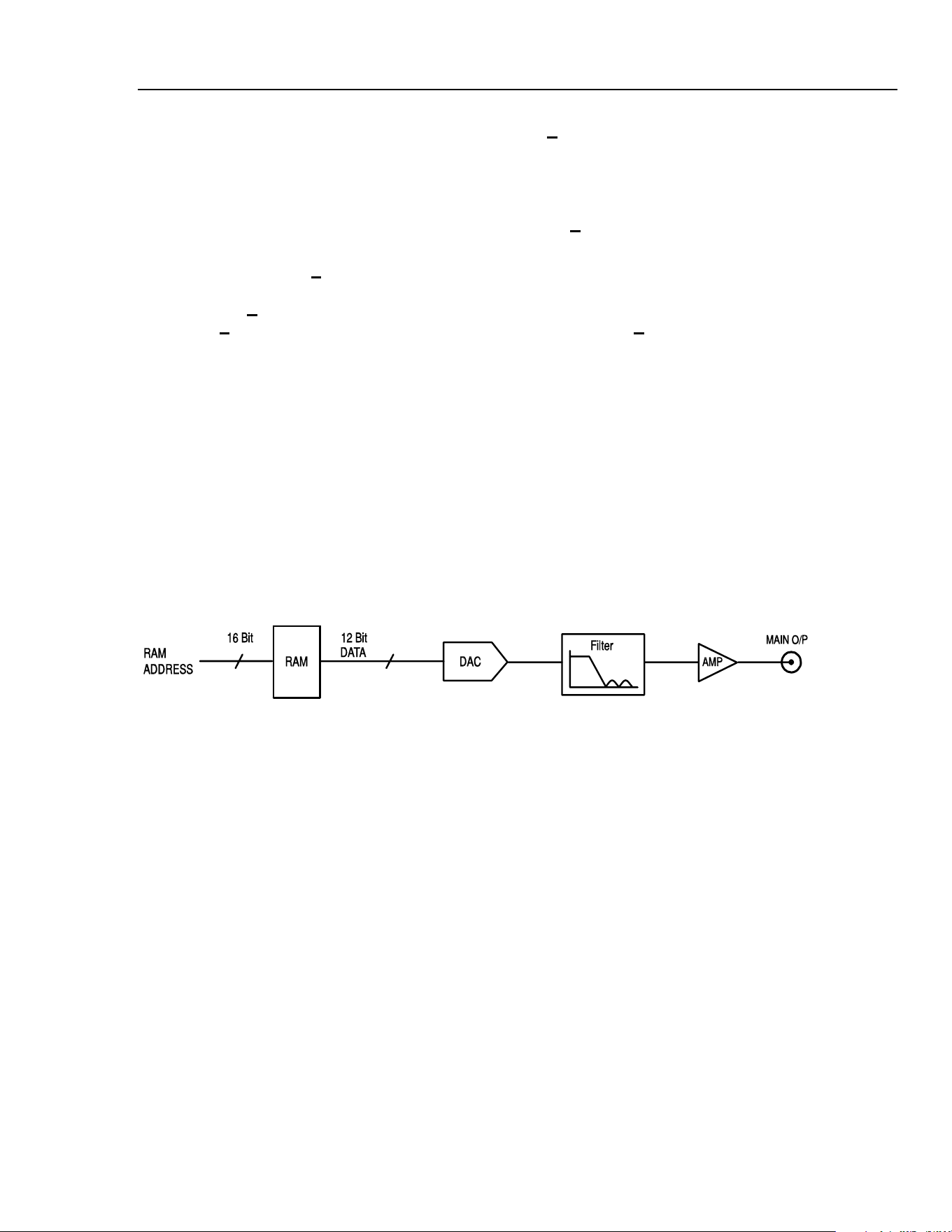
In both modes the waveform data is stored in RAM. As the RAM address is incremented
the values are output sequentially to a digital-to-analogue converter (DAC) which
reconstructs the waveform as a series of voltages steps which are subsequently filtered
before being passed to the MAIN OUT connector.
shb0005f.emf
Figure 4-1. Single-Channel Simplified Block Diagram
The main differences between DDS and clock synthesis modes are the way in which the
addresses are generated for the RAM and the length of the waveform data.
Clock Synthesis Mode
In clock synthesis mode the addresses are always sequential (an increment of one) and
the clock rate is adjusted by the user in the range 40 MHz to 0·1 Hz. The frequency of the
waveform is the clock frequency divided by the waveform length, thus allowing short
waveforms to be played out at higher repetition rates than long waveforms.
For example the maximum frequency of a 4 point waveform is 40,000,000÷4 or 10 MHz,
but a 1000 point waveform has a maximum frequency of 40,000,000÷1000 or 40 kHz.
Arbitrary waveforms have a user defined length of 4 to 65,536 points. Square waves use
a fixed length of 2 points and pulse and pulse train have their length defined by the user
selected period value.
4-5
1.888.610.7664 sales@GlobalTestSupply.com
Fluke-Direct.com
Loading ...
Loading ...
Loading ...