Loading ...
Loading ...
Loading ...
Stage and Local I/O Rack Overview 53
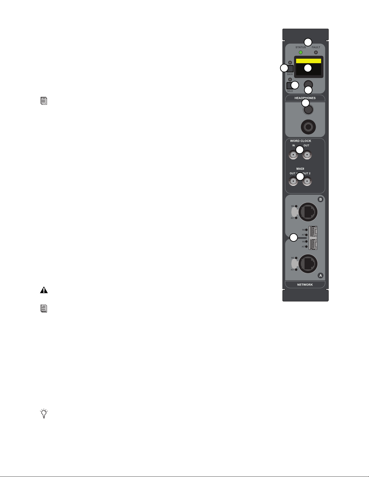
Stage 64 Controller
All Stage 64 I/O racks include a Controller. The Controller provides the following features:
1 – Status and Fault LEDs
These LEDs provide the following indications:
STATUS
Indicates the current status of the audio network connection to the Stage 64 Network ports.
FAULT
Indicates the current status of the Stage 64 hardware, such as fan and internal temperature.
2 – Stage 64 Controller Display
This display shows the current settings of the Stage 64 (via the HOME page), and provides access to var-
ious pages of Stage 64 parameters. For more information see Stage 64 Controller Display.
3 – Display Selector
This knob lets you navigate through the pages and change the configurable settings provided in the display.
4 – Back
This button lets you back out of the pages and sub-pages provided in the display.
5 – Solo
This switch sends the channel selected in the Controller Menu to the Stage 64 Headphones output.
6 – Headphones
This section provides a 1/4-inch stereo jack and a level control to monitor Stage 64 input and output chan-
nel signals. For more information see
Using the Stage 64 Confidence Monitor.
7 – Word Clock In and Out
(Two 75 Ohm Coaxial BNC Connectors)
The Word Clock Out port provides S6L system word clock output to sync external digital devices to the
S6L system.
8 – MADI Out 1 and 2
(Two 75 Ohm Coaxial BNC Connectors)
MADI Outs 1–2 provide fixed one-for-one digital splits of up to 64 inputs from the Stage 64. For more information, see
Using
MADI Outs on Stage 64 and Stage 32.
9 – Network A and B
(Two RJ-45 Ports with etherCON Connectors and two SFP module-compatible fiber-optic ports)
Stage 64 provides two connections (A and B) to connect Stage 64 to other S6L system components. Each connection provides an
RJ-45 with etherCON connector for copper connections, and an SFP module-compatible fiber-optic port for fiber-optic connec-
tions.
See
S6L System Components LED Codes for more information on LED codes.
The Word Clock In port is not functional.
S6L system digital inputs also provide sample rate conversion (SRC) for synchronizing digital inputs.
See
Synchronizing AES/ADAT Digital Audio Inputs (SRC) for more information.
Only one type of connection (copper or fiber-optic) can be active at a time for each port. Never connect both copper and fiber
to the same port (A or B).
Home >
<empty-name> 96k
Net OK Mon On
HW OK MADI On
1
2
6
7
8
9
3
4
5
Loading ...
Loading ...
Loading ...