Loading ...
Loading ...
Loading ...
Plug-Ins 283
Rack Slots
Each rack provides ten plug-in slots. You can assign any installed plug-in to any available rack slot.
Rack Slot Controls
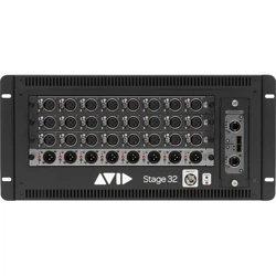
Each rack slot provides the following controls to select and manage plug-ins:
1 – Power (Config Mode Only)
Power turns the rack slot on or off. When off, the plug-in consumes no DSP.
2 – In/Out (Bypass)
The In/Out switch takes the rack slot in or out of circuit (bypasses the slot and any plug-in assigned to it).
3 – Input Selector
The Input selector displays a menu of input sources for a plug-in. Use this to designate the plug-in as a channel insert or a bus pro-
cessor by choosing from the Inserts or Bus sub-menus. For more information, see Routing Plug-Ins.
Once a plug-in has been routed, its input source is displayed in the Input area of each rack slot, as follows:
• If the plug-in is being used as an insert, the channel or bus name and number is shown, for example, Kick (Ch 1) or Aux (1–2).
The Channel Insert/Bus Output selector automatically switches to Channel Insert mode, showing the insert point occupied by
the plug-in.
• If the plug-in is on a bus, the selected bus source is shown in the Input selector, for example, Aux 1 or Grp 1. The Channel In-
sert/Bus Output selector can be used to assign the output routing of the plug-in to a channel or bus.
4 – Channel Insert or Output Selector
The Channel Insert/Output selector displays different choices depending on whether the plug-in is being used as a channel insert,
or as a bus processor, as follows:
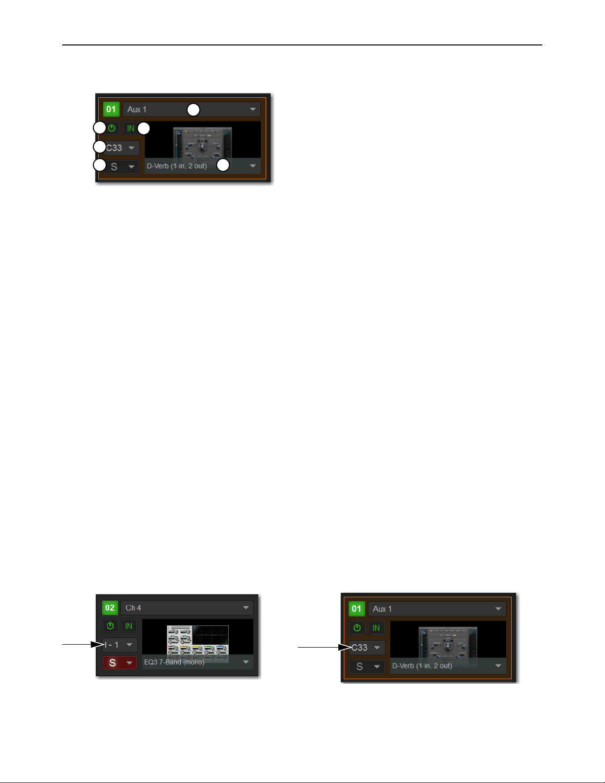
• If the plug-in is being used as a channel insert, the Channel Insert Selector shows the four insert points on that channel (1–4).
The letter “I” is shown before the insert number (for example, I–1 indicates the current plug-in is inserted into the first insert
position on its channel).
• If the plug-in is being used as a bus processor, the selector is an Output selector, used to select the destination for plug-in out-
put,. When the plug-in is routed, the selector shows the channel to which the plug-in output is assigned.
A rack slot and its controls, with an assigned plug-in shown
A rack slot shown an inserted mono plug-in (left) and a stereo plug-in assigned as a bus processor (right)
1
2
3
4
56
Loading ...
Loading ...
Loading ...