Loading ...
Loading ...
Loading ...
S6L Control Surface Overview 26
Channel Touch Module (CTM)
The S6L-32D provides three Channel Touch Modules (CTM), and the S6L-24D provides two CTMs. Each CTM is located above
a CKM, and is functionally associated with that CKM and the fader bank below it. The CTM provides a local view of the channels
banked to the associated fader bank. Using the CTM’s touch capabilities, you can select channel functions and spill those param-
eters to the associated CKM. The CTM provides two views, Meters view and Channel view.
Meters View
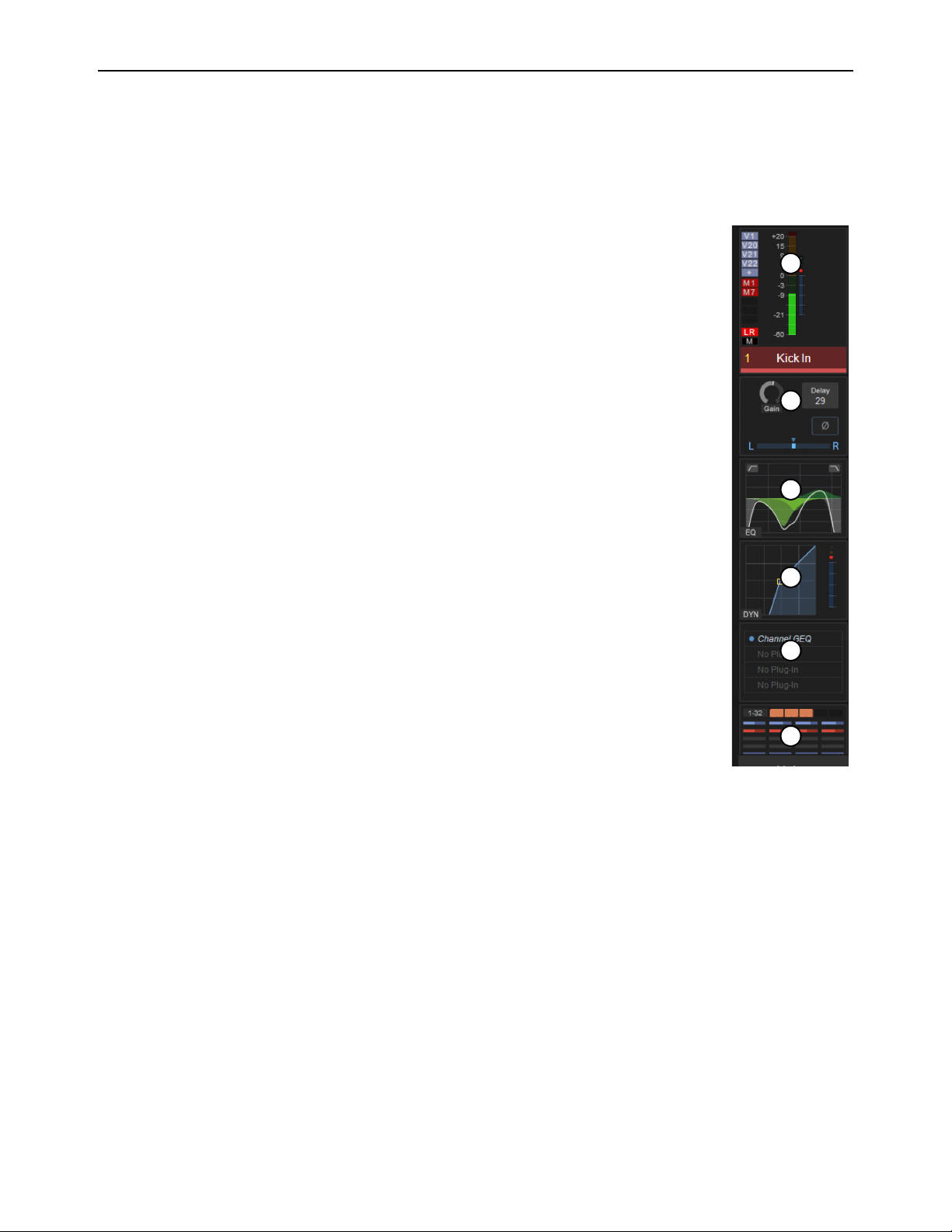
Meters view displays parameters for each channel vertically, like a “virtual channel strip.” Each strip is
composed of parameter touch zones that show the status of certain parameters for the associated chan-
nel. Parameters in each touch zone are lit when that parameter is on, and dimmed when off.
Touching a parameter touch zone simultaneously locally selects the corresponding channel and assigns
the touch zone’s parameters to the associated CKM in Channel Control mode. The active zone is indi-
cated by an orange border. Touching an active zone de-selects the corresponding channel. Each virtual
channel strip provides the following parameter touch zones:
1 – Meters and Assignments
This zone shows the associated channel’s channel number and name, and level and gain reduction for the
channel. Touching this zone changes the view on the CTM to a Channel view of the currently selected
channel.
To the left of the meters are (from top to bottom) VCA, Mute Group, and Mains bus assignment indica-
tors.
2 – Input
This zone shows a selection of input or output channel parameters. Touching this zone mirrors the func-
tion of the INPUT Channel Control Function switch.
3 – EQ
This zone shows the current EQ curve applied to the channel. Touching this zone mirrors the function
of the EQ Channel Control Function switch.
4 – Dynamics
This zone shows a composite dynamics graph for the channel. Touching this zone mirrors the function
of the DYNAMICS Channel Control Function switch.
5 – Plug-Ins
This zone shows the channel’s Inserts slots, and any plug-ins inserted in those slots. Touching this zone mirrors the function of the
PLUG-INS Channel Control Function switch.
6 – Aux Sends/Members/Matrix Mixer Inputs
This zone shows the following, depending on the type of channel banked to the corresponding channel strip:
Aux Sends and Groups
For input channels, this zone shows the channel’s Aux Sends in sets of 32, and Group bus assignments.
Each send is represented by a thermometer-style meter showing individual send level and on/off status (lit is on). Touching this
zone assigns the set of Aux sends indicated in the display (1–32, 33–64, 65–96, as available) to the associated CKM.
Members
This zone shows Aux output, Group output, Mains output, or VCA members (channels assigned to that bus or VCA),
their send levels, and on/off status in sets of 32. Touching this zone assigns the set of members indicated in the display (1–32,
33–64, 65–96, as available) to the CKM.
Matrix Mixers
For Matrix Mixers, this zone shows Matrix Mixer members (channels assigned to that Matrix Mixer), their input lev-
els, and on/off status. Touching this zone assigns the available Matrix Mixer input controls for the selected Matrix Mixer to the
CKM.
G1 G3 G8
1
3
2
6
4
5
Loading ...
Loading ...
Loading ...