Loading ...
Loading ...
Loading ...
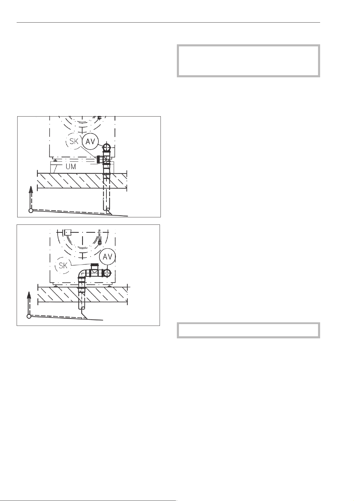
Water drainage
Dump valve drainage (AV) DN 70 on the machine
side, DN 70 socket on-site. Transient flow rate 200
l/min.
Foam compensator (SK)
Increased foaming can lead to foam being
discharged from the vapour vent. A drain with siphon
(commercial off-the-shelf pipe material) can be
retro-fitted to dispose of the foam.
Installation examples
Electrical connection
The electrical connection must only be carried out
by a suitably qualified electrician in accordance
with local and national safety regulations.
The connection terminal is located behind the cover.
The machine must only be connected to the voltage
and frequency shown on the data plate.
The machine is equipped with a multi-tap
transformer.
If the applicance is hard wired, a multi-pole separator
must be installed. An appropriate separator is a
switch with a contact opening of at least 1/8" (3 mm).
This includes circuit breakers, fuses and switches.
The plug connection or the separator must always be
accessible.
Connection should be made in accordance with the
wiring diagram and installation diagram to a suitable
isolator, with an on-off switch which is easily
accessible for servicing. The wiring and installation
diagrams are important for the correct electrical
functioning of the machine.
If the machine is disconnected from the electricity
supply ensure adequate measures are taken to
ensure that it cannot be reconnected to the electricity
supply until all work has been carried out.
Potential equalization
Potential equalization must be provided if the leak
current exceeds 10mA.
To activate the heating the water level in the drum
must be 2" (50cm) high.
A motor overload protection is located in the motor
winding.
See the enclosed wiring and installation diagrams.
Installation and connection
36
Loading ...
Loading ...
Loading ...