
Loading ...
Loading ...
Loading ...
FP (E1.1) 03/2019 page 51/90
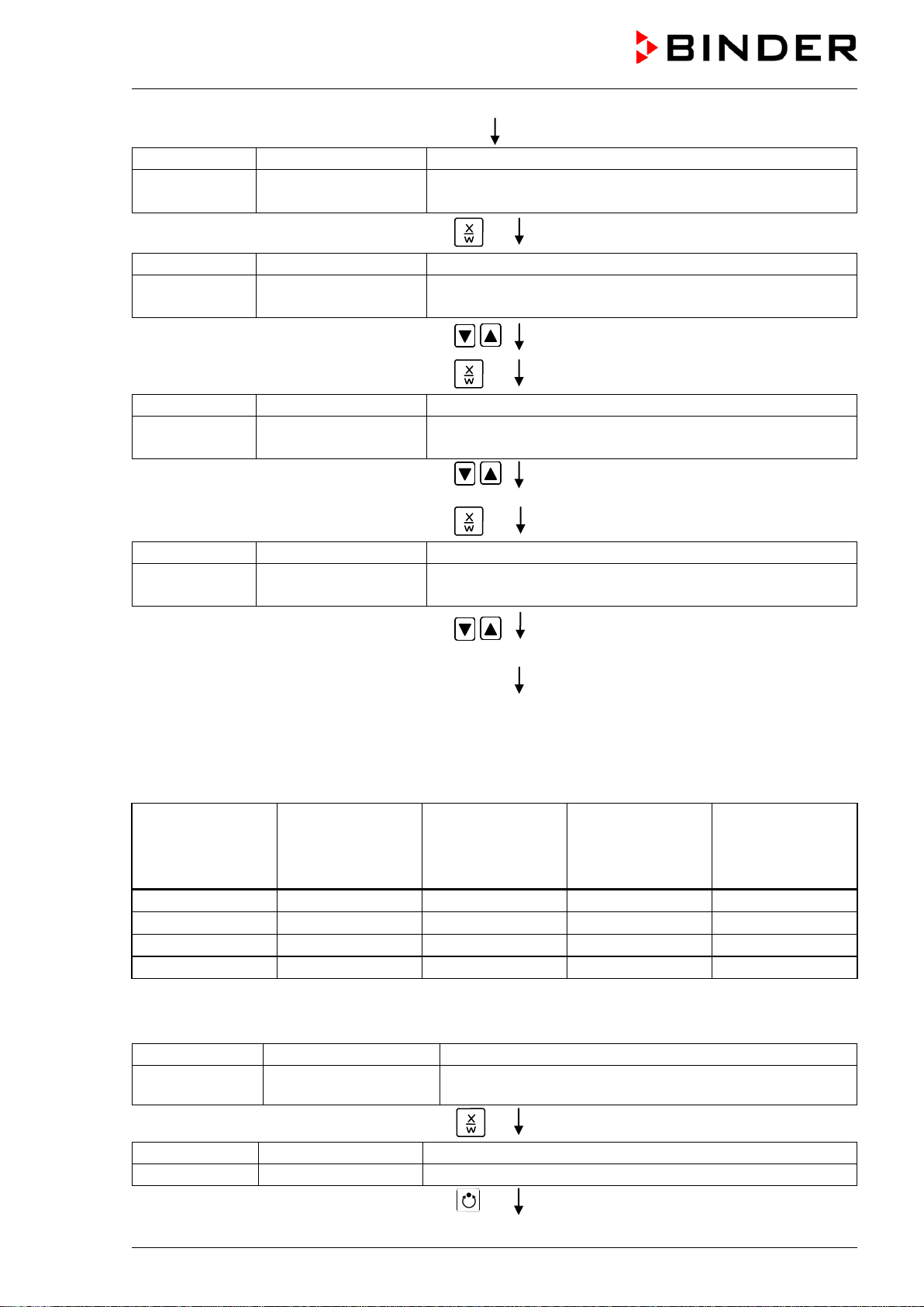
Display 1 shows
1
(actual address)
Display 2 shows Adress 1
(entry of chamber address)
(actual address: 1)
Hit several times key
until Prg.Time appears:
Display 1 shows
0000
Display 2 shows Prg.Time:
999:59
(max. section length 99:59 or 999:59?)
(actual setting: 999:59)
Select 999:59 in hhh:mm with arrow keys
Setting is displayed in display 2.
Hit key
Display 1 shows
0000
Display 2 shows Tol.Band 0
(Tolerance limits in °C)
(actual setting: 0)
Set value 0 meaning tolerance limits off with
arrow keys
Setting is displayed in display 2.
Hit key
Display 1 shows
0000
Display 2 shows Prog.Clk Inactive
(Week program timer active or inactive?
(actual setting: Inactive)
Select “Inactive” meaning week program
timer off, with arrow keys
Setting is displayed in display 2.
Hit several times key
EXIT
or wait 120 sec.
Controller returns to Normal Display.
2. Enter the time program to the program editor
Program table for the example program:
Section
SEC
Temperature
set-point
[ °C]
TEMP
Section length
[hh.mm]
TIME
Fan speed
[%]
FAN
Operation lines
O.LINE
S01
60
119:59
100
000
S02
60
000:01
100
000
S03
30
047:59
100
000
S04
30
000:01
100
000
In this example the program is entered to the first program place (P01).
Normal display
Display 1 shows
e.g. 19.8
(actual temperature value)
Display 2 shows e.g. 15.05.06 13:52 - -
(actual date and time, actual switching state of week
program timer channel 1: Off, channel 2: Off)
Hit key
for 5 sec.
Display 1 shows
e.g. 0000
Display 2 shows
PROGRAM EDITOR
(you are in the program editor)
Hit program key
Loading ...
Loading ...
Loading ...