Loading ...
Loading ...
Loading ...
Controller Operation
9.4 Temperature Display Hold 9
9-5
9.4.1 Hold Temperature Display
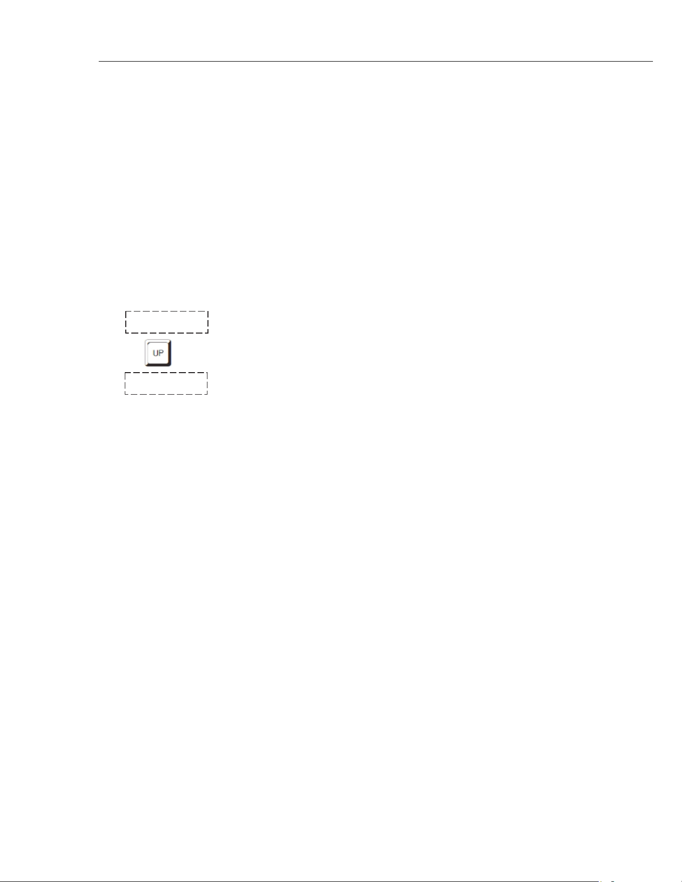
The hold feature is enabled by simply pressing the “UP” button when the
temperature is displayed. The hold temperature display shows the hold
temperature on the right and the switch status on the left. For the status “c”
means the switch is closed and “o” means the switch is open. The status flashes
when the switch is in its active position (opposite the normal position). The hold
temperature shows what the temperature of the well was when the switch
changed from its normal position to its active position. While the switch is in the
normal position the hold temperature will follow the well temperature.
If the Scan Control is “OFF” and the Hold Temperature Display is being used, the
temperature at which the switch is activated does not affect the set-point
temperature. However, if the Scan Control is “ON” and the Hold Temperature
Display is being used, the temperature at which the switch is activated is stored
as the new set-point temperature.
Operation of the hold temperature display is outlined below.
143.50C Well temperature display
Access hold display
c 144.8 Switch status and hold temperature
To return to the normal well temperature display press “DOWN”.
9.4.2 Mode Setting
The Hold Function is always in the automatic mode. In this mode the normal
position is set to whatever the switch position is when the set-point is changed.
For example, if the switch is currently open when the set-point is changed, the
closed position then becomes the new active position. The normal position will be
set automatically under any of the following conditions, (1) a new set-point
number is selected, (2)the set-point value is changed, (3) a new set-point is set
through the communications channels.
9.4.3 Switch Wiring
The thermal switch or cut-out is wired to the calibrator at the two terminals on the
back of the Micro-Bath labeled “DISPLAY HOLD”. The switch wires may be
connected to the terminals either way. Internally the black terminal connects to
ground. The red terminal connects to +5V through a 100 kW resistor. The
calibrator measures the voltage at the red terminal and interprets +5V as open
and 0V as closed.
1.888.610.7664 sales@GlobalTestSupply.com
Fluke-Direct.com
Loading ...
Loading ...
Loading ...