Loading ...
Loading ...
Loading ...
Chapter 5 To Trigger the Oscilloscope RIGOL
MSO5000 User Guide 5-5
are forced and acquisitions are made so as to display the waveforms. This trigger
mode should be used when the signal level is unknown or the DC should be
displayed as well as when forcible trigger is not necessary as the trigger condition
always occurs.
⚫ Normal: In this trigger mode, triggers and acquisitions only occur when the specified
trigger conditions are found. This trigger mode should be used when the signal is
with low repetition rate or only the event specified by the trigger setting needs to be
sampled as well as when auto trigger should be prevented to acquire stable display.
⚫ Single: In this trigger mode, the oscilloscope performs a single trigger and
acquisition when the specified trigger conditions are found, and then stops. This
trigger mode should be used when you need to perform a single acquisition of
the specified event and analyze the acquisition result (you can pan and zoom
the currently displayed waveform, and the subsequent waveform data will not
overwrite the current waveform). After a single trigger mode is initiated, the
operating status of the oscilloscope is in "STOP" state.
Note: In "Normal" and "Single" trigger modes, pressing Force can generate a
trigger signal forcibly.
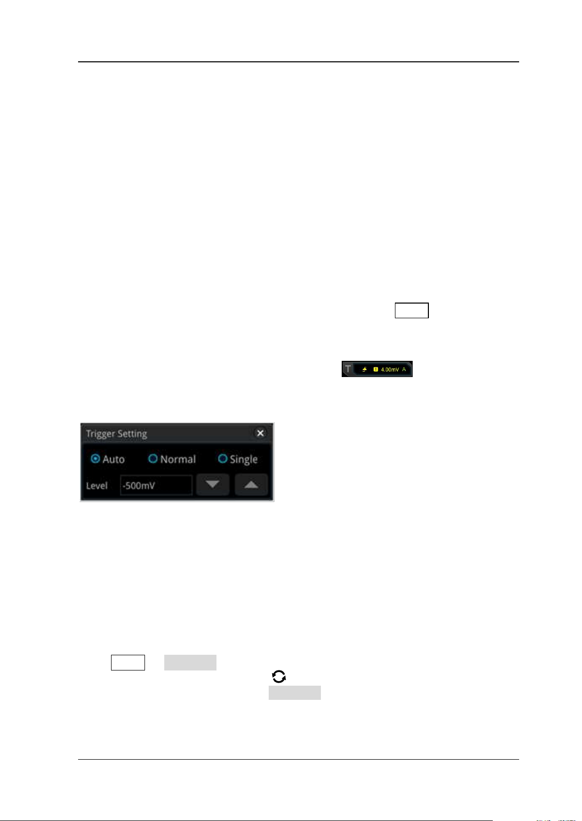
In addition, you can enable the touch screen to set the trigger mode. Enable the
touch screen and tap the trigger setting label
at the upper-right
corner of the screen. Then the following window is displayed. Tap to select "Auto",
"Normal", or "Single" as the trigger mode.
Trigger Coupling
Trigger coupling decides which kind of components will be transmitted to the trigger
module. Please distinguish it from "Channel Coupling".
Note: Trigger coupling is only valid when the trigger type is Edge and the trigger
source is an analog channel.
Press Menu → Coupling in the trigger control area (Trigger) on the front panel.
Then, rotate the multifunction knob to select the desired coupling mode (by
default, it is DC). You can also press Coupling continuously to select it or enable the
touch screen to select the desired coupling mode with touch gestures.
⚫ DC: allows DC and AC components to pass the trigger path.
Loading ...
Loading ...
Loading ...