Loading ...
Loading ...
Loading ...
76
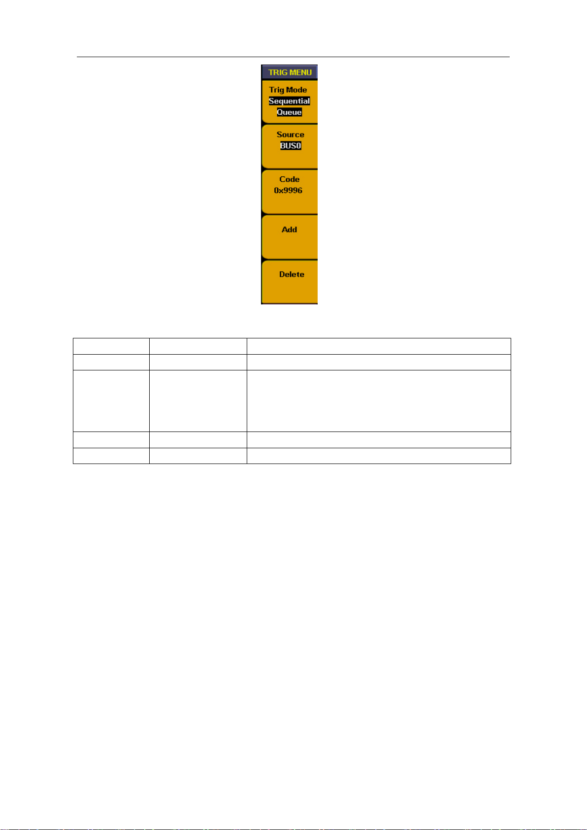
Fig.5-60:Sequential queue trigger
Sequential queue trigger function as below:
Function
Setting
Instruction
Source
BUS0
~
BUS3
Select the trigger source from BUS0~BUS3
Code
0x0000
~
0xffff
(HEX)
0~65535
(
DEC
)
Can be set discretionarily between 0x0000 and 0xffff
(HEX)
or between 0 and 65535 (DEC)according to the bus
and code setting.
Add
Add the code type to the queue
Delete
Delete the code type from the queue
For example, to set a 16 bit data Bus signal, there will have 4 value as 0X9999、0X9998、
0X9997、0X9996 in the bus. We set BUS0 to include 16 measure channels and make
above 4 values as trigger condition to observe the data bus. Trigger setting follow up
below steps:
A. Press "Trigger MENU" and menu appears.
B. Press "F1" till trigger mode display as "Sequential Queue".
C. Press "F2" till signal source display as "BUS0"
D. Press "F3" and data in code type as red background and green digital indicator on, then
insert data value "0X9999" and set code as "0X9999". Press "F3" again and red
background disappeared. Repeat operation of step D if setting error or need to be
modified,
E. Press "F4" and add setting value into the trigger queue, then info window will display
the value of "0X9999".
F. Repeat the operation of step D. E, and add "0X9998"
、
"0X9997"
、
" 0X9996" to trigger
queue. Then info window will display value of "0X9999"
、
"0X9998"
、
" 0X9997"
、
" 0X9996".
G. Press "F5" and delete the queue value if queue adding in error and add again.
H. Turn "Trigger level " adjust knob or press "set 50%"till trigger position display as
"NEXT T POS = 50%".
Loading ...
Loading ...
Loading ...