Loading ...
Loading ...
Loading ...
38
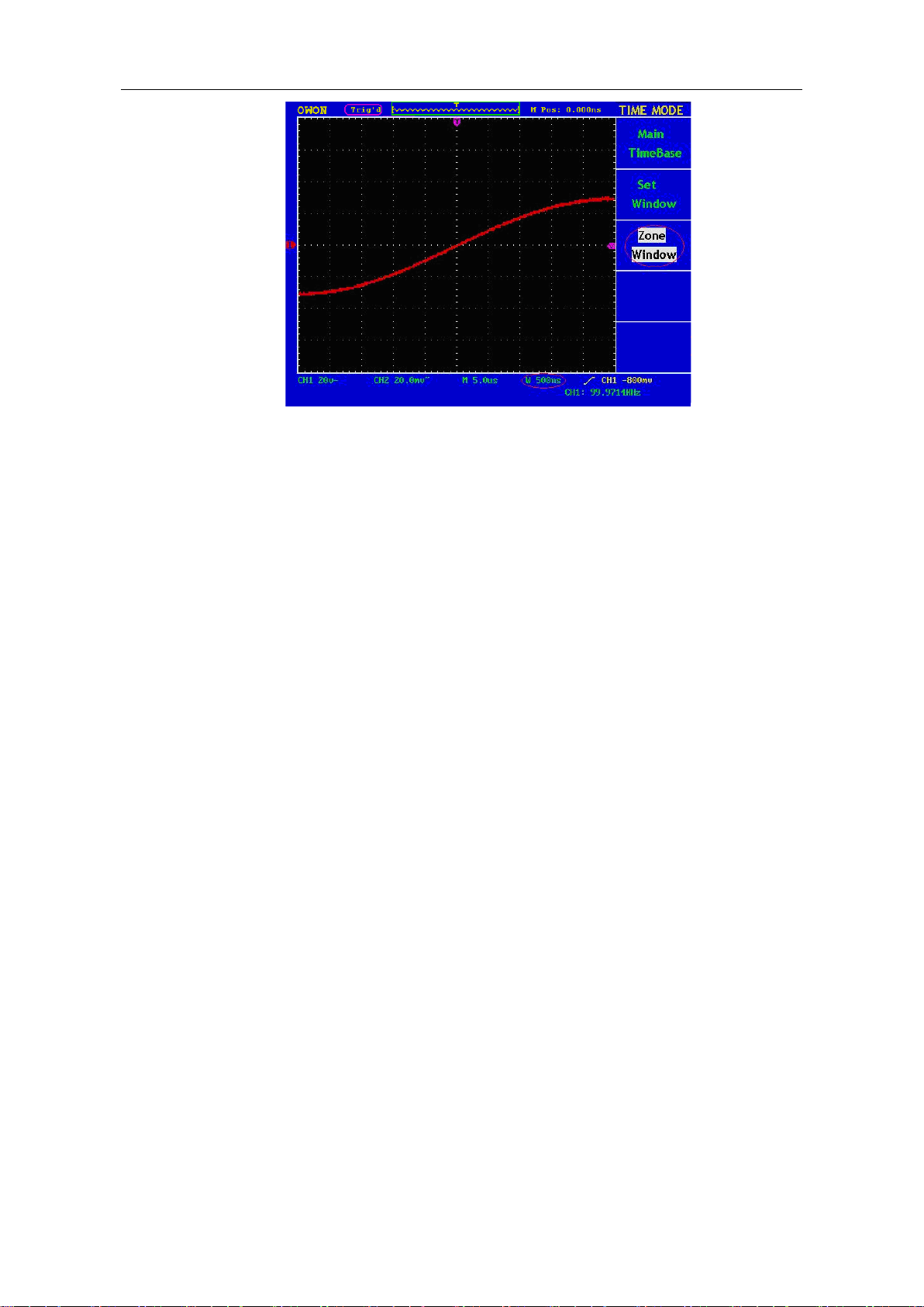
Fig. 5-18 Zone Window
How to set trigger system
When the oscilloscope begins to collect the data and display the wave form depends
on a trigger. Once it is set correctly, the trigger can transfer the unstable display into a
meaningful wave form.
When beginning to collect data, the oscilloscope will collect adequate data to draw the
wave form at the left side of the trigger point at first. It will continuously perform the
data acquisition while waiting for the trigger condition. After a trigger is detected, the
oscilloscope will continuously collect data enough to draw the wave form at the right
side of the trigger point.
One knob and four function menu buttons are included in the trigger control zone.
TRIG LEVEL: Trigger the level control knob and set the signal voltage
corresponding to the trigger point.
SET TO 50%: Set the trigger level as the vertical midpoint value of the amplitude of
the trigger signal.
FORCE TRIG: It is a force trigger button for the generation of a trigger signal,
which is mainly used in the "Normal" and "Single" triggering modes.
SET TO ZERO: Trigger the resetting of the horizontal position.
TRIG MENU: It is a trigger menu button. When it is pressed, an operation menu
will be presented in the screen.
Trigger Control
The oscilloscope provides two trigger types: single trigger and alternate trigger. Press
F1 to choose.
Single trigger: Use a trigger level to capture stable waveforms in two channels
simultaneously
Alternate trigger: Trigger on non-synchronized signals.
Loading ...
Loading ...
Loading ...