Loading ...
Loading ...
Loading ...
3
Warning:
The channels should adopt common basis during measuring. To prevent short
circuits, the 2 probe ground must not be connected to 2 different non-isolated DC
level.
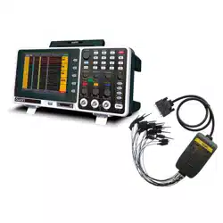
The diagram of the oscilloscope ground wire connection:
Ground Clip
Signal Input
Oscilloscope
Electrical Outlet
Probe
Power Cord
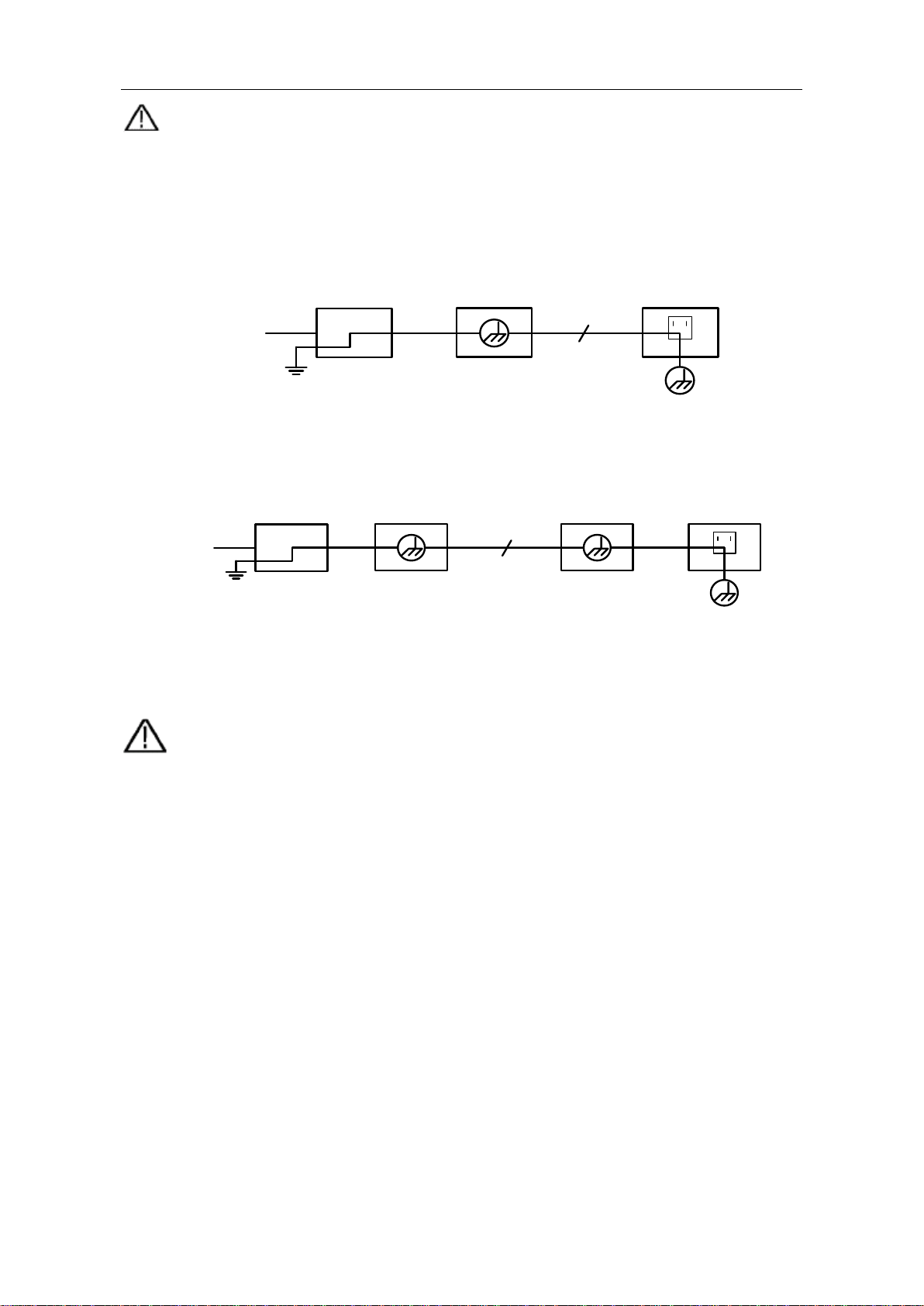
The diagram of the ground wire connection when the battery-powered oscilloscope is
connected to the AC-powered PC through the ports:
Ground Clip
Signal Input
Oscilloscope
(Battery-power)
PC Electrical OutletProbe
USB/COM Cable
It is not allowed to measure AC power when the oscilloscope is AC powered, or when
the battery-powered oscilloscope is connected to the AC-powered PC through the
ports.
Warning:
To avoid fire or electrical shock
, when the oscilloscope input signal
connected
is more than
42V peak (30Vrms) or on circuits of more than
4800VA
, please take note of below items:
Only use accessory insulated voltage probes and test lead.
Check the accessories such as probe before use and replace it if
there are any damages.
Remove probes, test leads and other accessories immediately after
use.
Remove USB cable which connects oscilloscope and computer.
Do not
apply input voltages above the rating of the instrument
because the probe tip voltage will directly transmit to the
oscilloscope. Use with caution when the probe is set as 1:1.
Do not use exposed metal BNC or banana plug connectors.
Do not insert metal objects into connectors.
Loading ...
Loading ...
Loading ...