Loading ...
Loading ...
Loading ...
18
4.3 Logic Analyzer
LA input connection
Insert the plug of OL-16 LA module 50P into the LA signal input on front panel and fix
two screw. Then 16 channel clamp of OL-16 LA connect to target signal and ready for
measurement
User interface introduction
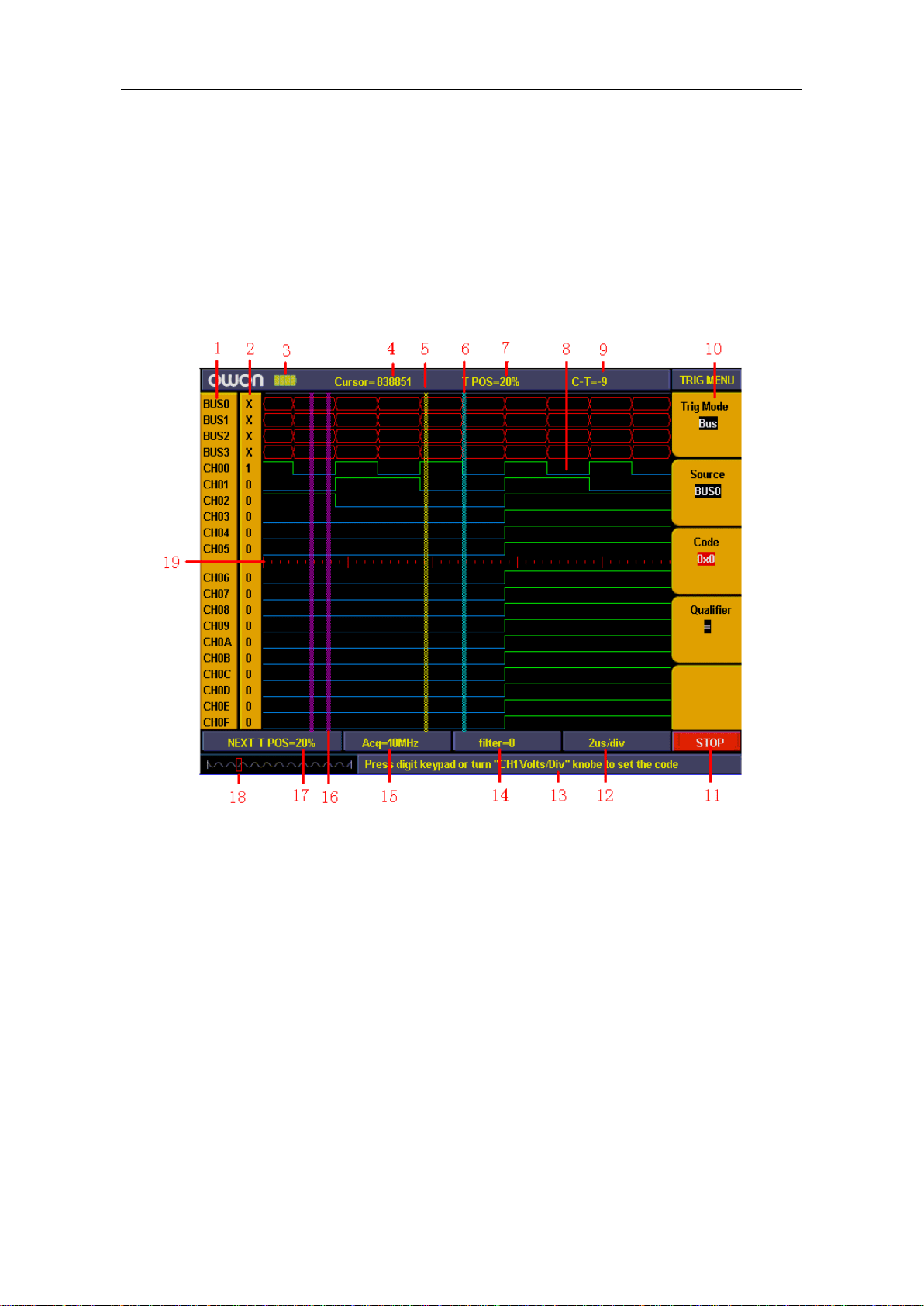
Fig.4-12:User interface of logic analyzer
1、Channel and Bus indicate: display current working channel and bus 。
2、Channel binary value display: display binary system value for the channel position in
current cursor 。
3、Battery powers indicate: indicate battery power when battery inside。
4、Decimal system value indicate the position of current cursor in storage area。
5、Yellow dashed line indicates current cursor。
6、Blue dashed line indicates current trigger position。
7、Percentage value indicate current trigger position in storage area。
8、Sample data area indication: red for bus, blue and green for "0", "1" in each channel
data。
9、Decimal system value indicate the position of current cursor relate to current trigger。
10、Operation options indicate current function menu and different function menu have
different display。
11、Sample status indicate: "RUN" for sampling and wait for trigger, "TRIG" for trigger
Loading ...
Loading ...
Loading ...