Loading ...
Loading ...
Loading ...
10
5. This reading shows the time deviation between the horizontal trigger position and
the window center line, which is regarded as 0 in the window center.
6. It indicates the current function menu.
7. It indicates the operation options for the current function menu, which changes
with the function menus.
8. The purple pointer shows the trigger level position.
9. The reading shows the trigger level value.
10. The reading shows the trigger source.
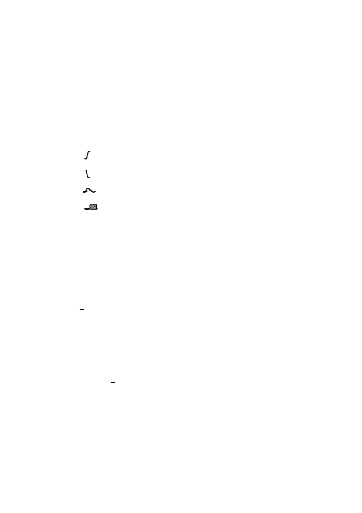
11. It shows the selected trigger type:
Rising edge triggering
Falling edge triggering
Video line synchronous triggering
Video field synchronous triggering
12. The reading shows the window time base set value.
13. The reading shows the main time base set value.
14. The two yellow dotted lines indicate the size of the viewing expanded window.
15. The icon shows the coupling mode of the CH2 channel.
"—" indicates the direct current coupling
" ~" indicates the AC coupling
" " indicates GND coupling.
16. The reading shows the vertical scale factor (the Voltage Division) of the CH2
channel.
17. The icon indicates the coupling mode of the CH1 channel:
The icon "–" indicates the direct current coupling
The icon "~" indicates the AC coupling
The icon " " indicates GND coupling.
18. The reading indicates the vertical scale factor (the Voltage Division) of the CH1
channel.
19. The information shows the zero point positions of CH1 or CH2 channel.
20. The yellow pointer shows the grounding datum point (zero point position) of the
waveform of the CH2 channel. If the pointer is not displayed, it shows that this
channel is not opened.
21. The red pointer indicates the grounding datum point (zero point position) of the
Loading ...
Loading ...
Loading ...