Loading ...
Loading ...
Loading ...
En
6
Connections and part names
Connections
! Connect the power cord to a power outlet after all the connections are completed.
Turn off this unit and disconnect the power cord from the power outlet before connecting components or changing the connections.
Refer to the operating instructions for the components to be connected.
! Be sure to use the supplied power cord.
! Be sure to use the USB cable included with this product or the one that conforms to USB 2.0.
Part names
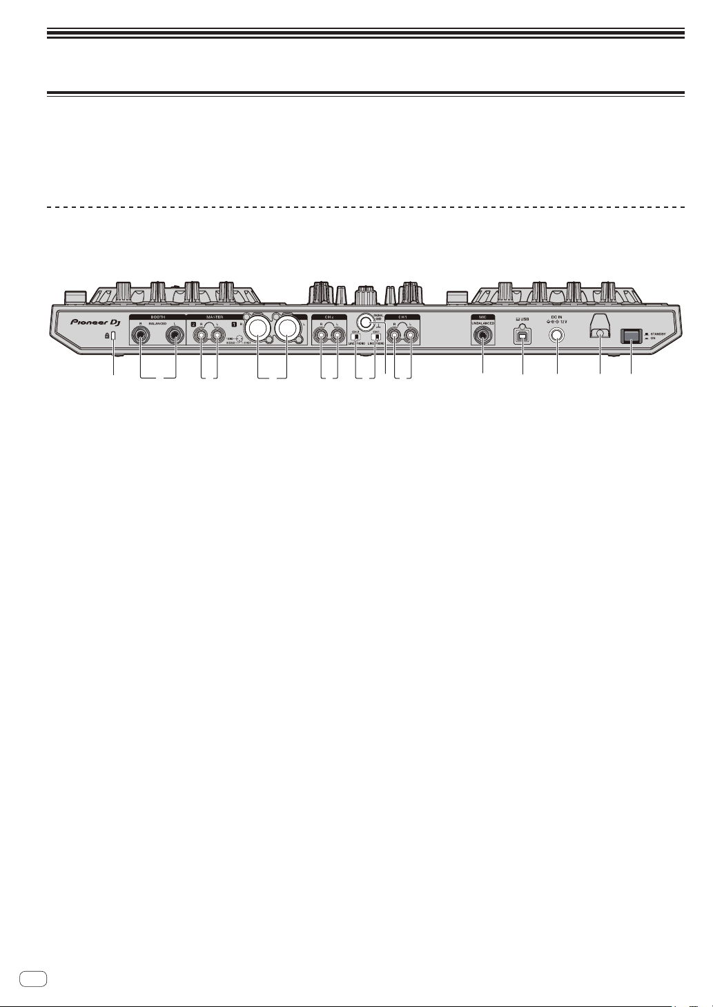
Rear panel
3 9 c
6
7 a2 41
5
8
5
b
1 Kensington security slot
2 BOOTH terminals
These are the output terminals for a booth monitor. Compatible with
balanced or unbalanced output for 1/4” TRS connectors.
The master channel sound can be output from the [BOOTH] output
terminals regardless of the audio level set for the master channel.
The volume level can be adjusted with the [BOOTH MONITOR]
control.
! The sound will be distorted if the level is raised too high when
using unbalanced outputs.
3 MASTER 2 terminals
Connect to a power amplifier, etc.
! Compatible with RCA pin-jack type unbalanced outputs.
4 MASTER 1 terminals
Connect powered speakers, etc., here.
! Compatible with XLR connector type balanced outputs.
! Be careful not to accidentally insert the power cord of
another unit to [MASTER 1] terminal.
! Do not connect the terminal that can supply phantom
power to the [MASTER 1] terminal.
5 PHONO/LINE input terminals
Connect a phono level (for MM cartridges) output device (analog
player, etc.) or a line level output device (DJ player, etc.). Switch
the input source according to the connected device using the
[PHONO/LINE] switch on this unit’s rear panel.
6 PHONO/LINE switches
Selects the input source for each channel from the components
connected to this unit.
— [PHONO]: Select this to use a phono level (for MM cartridges)
output device (analog player, etc.) connected to the [PHONO/
LINE] input terminals.
— [LINE]: Select this to use a line level output device (DJ player,
etc.) connected to the [PHONO/LINE] input terminals.
7 SIGNAL GND terminal
Connect a ground wire of an analog player to reduce noise that
occurs when an analog player is connected.
8 MIC terminal
Connect a microphone.
! Compatible with a 1/4” TS jack.
9 USB port
Connect to a computer.
! Connect this unit and the computer directly using the included
USB cable.
! A USB hub cannot be used.
a DC IN terminal
Connect to a power outlet using the included AC adapter (with the
included power cord connected).
b Cord hook
Catch the AC adapter’s power cord and USB cable on this hook
when using this unit.
c STANDBY/ON switch
This switches this unit’s power between on and standby.
Loading ...
Loading ...
Loading ...