Loading ...
Loading ...
Loading ...
4-28
FUEL
E
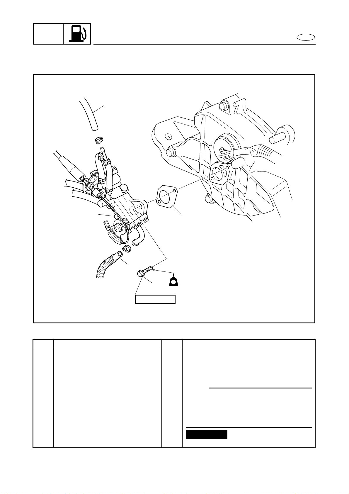
OIL PUMP
OIL PUMP
EXPLODED DIAGRAM
REMOVAL AND INSTALLATION CHART
Step Procedure/Part name Q’ty Service points
OIL PUMP REMOVAL Follow the left “Step” for removal.
Exhaust chamber assembly Refer to “CARBURETOR UNIT”.
Oil pump cable and oil feed
hoses
Refer to “CARBURETOR UNIT”.
1 Oil return hose 1
NOTE:
When removing the oil pump, the exhaust
chamber assembly does not need to be
removed if the engine unit has already
been removed.
2 Oil hose 1
3 Bolt 2
4 Oil pump assembly 1
5 Gasket 1
Reverse the removal steps for installation.
4
2
6 × 20 mm
LTLT
LT
572572
3
5
1
Not reusable
Loading ...
Loading ...
Loading ...