Loading ...
Loading ...
Loading ...
6-1
E
JET
PUMP
JET PUMP UNIT
JET PUMP UNIT
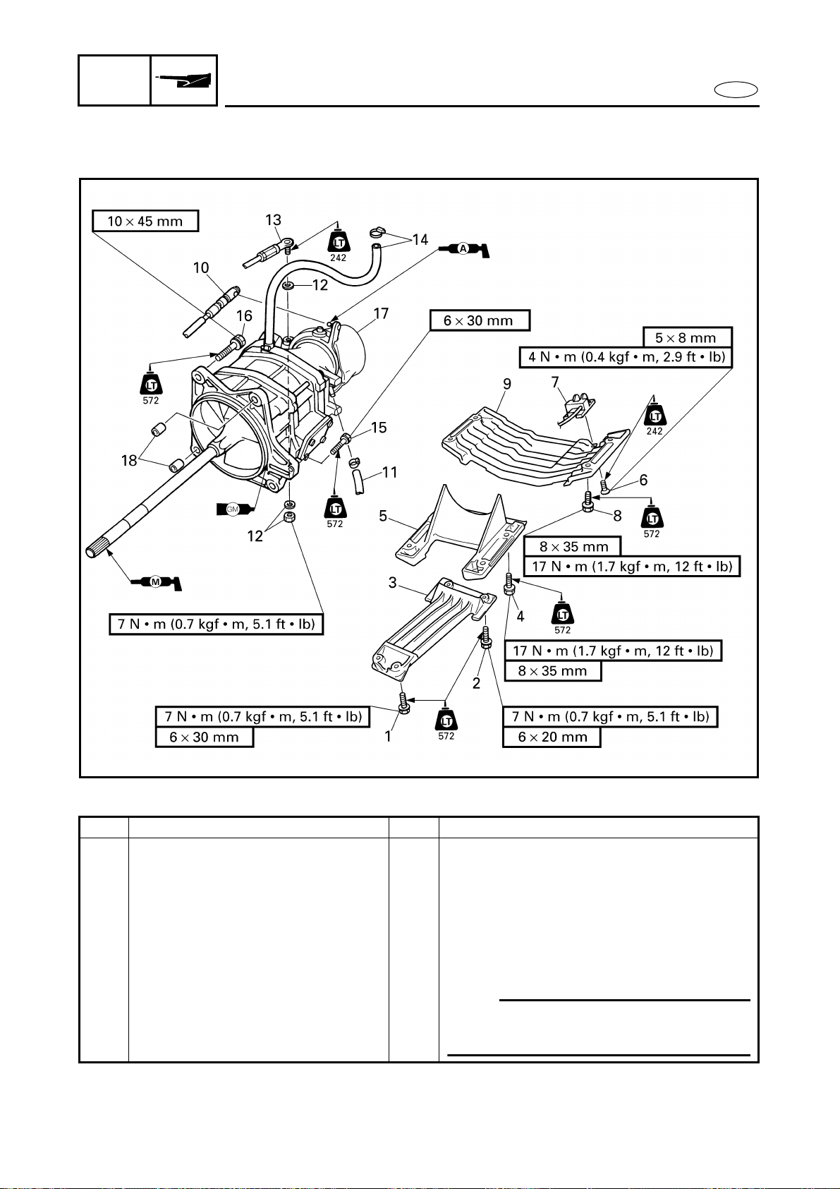
EXPLODED DIAGRAM
REMOVAL AND INSTALLATION CHART
Step Procedure/Part name Q’ty Service points
JET PUMP UNIT REMOVAL Follow the left “Step” for removal.
1 Bolt 2
2 Bolt 2
3 Intake grate 1
4 Bolt 4
5 Intake duct 1
6 Screw 4
7 Speed sensor 1
NOTE:
Route the speed sensor lead between the
jet pump unit and the bilge hose.
Loading ...
Loading ...
Loading ...