Loading ...
Loading ...
Loading ...
4-11
FUEL
E
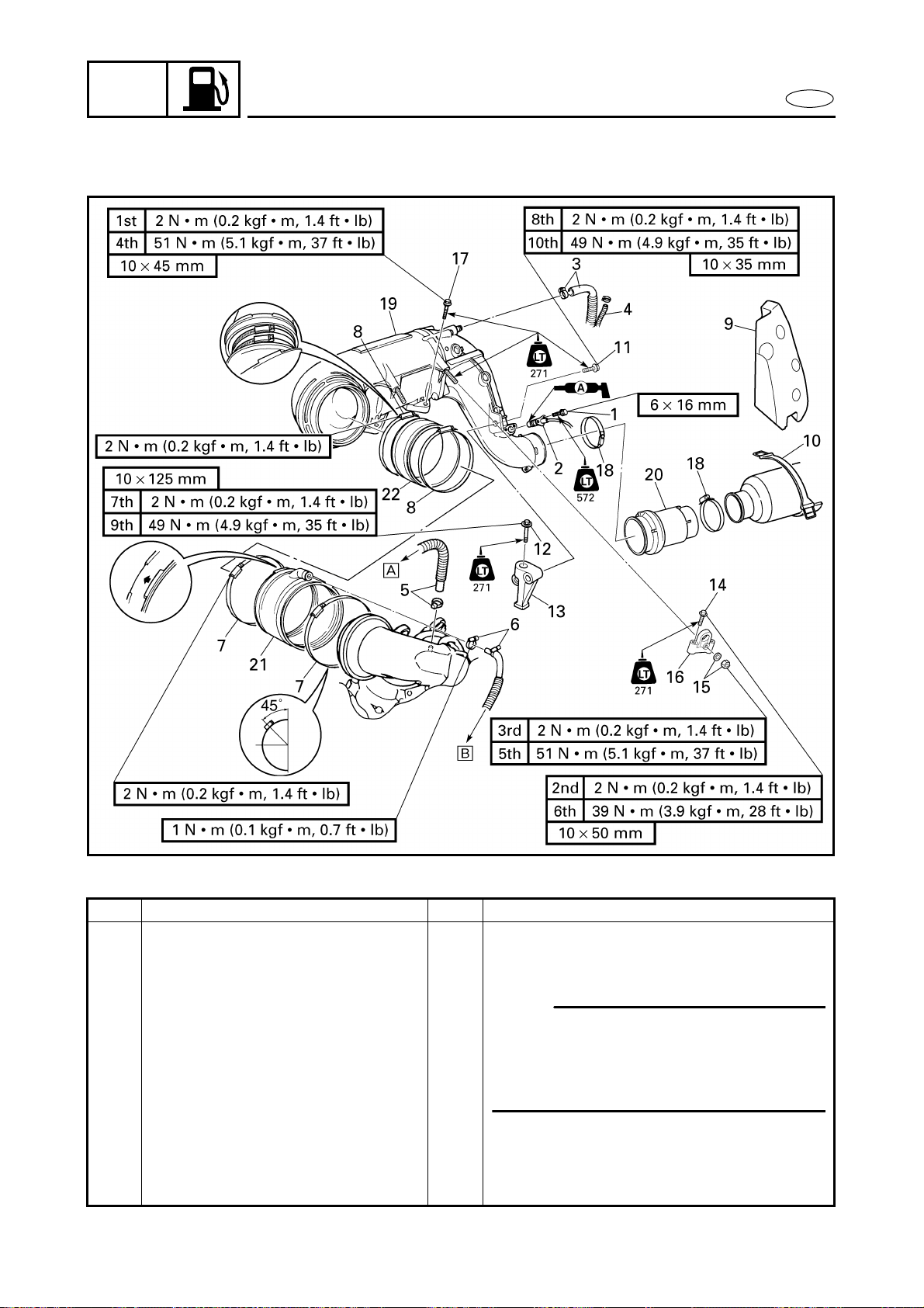
CARBURETOR UNIT
CARBURETOR UNIT
EXPLODED DIAGRAM
REMOVAL AND INSTALLATION CHART
Step Procedure/Part name Q’ty Service points
CARBURETOR REMOVAL Follow the left “Step” for removal.
Battery box Refer to “BATTERY BOX” in chapter 8.
Intake silencer Refer to “INTAKE SILENCER”.
1 Bolt 2
NOTE:
When removing the carburetor, the
exhaust chamber assembly does not
need to be removed if the engine unit has
already been removed.
2 Thermoswitch 1
3 Clamp/cooling water hose 1/1
4 Grease hose 1
5 Clamp/cooling water hose 1/1 Å For cooling water pilot outlet on
starboard side
6 Clamp/cooling water hose 1/1 ı For cooling water pilot outlet on port
side
Loading ...
Loading ...
Loading ...