Loading ...
Loading ...
Loading ...
5-18
POWR
E
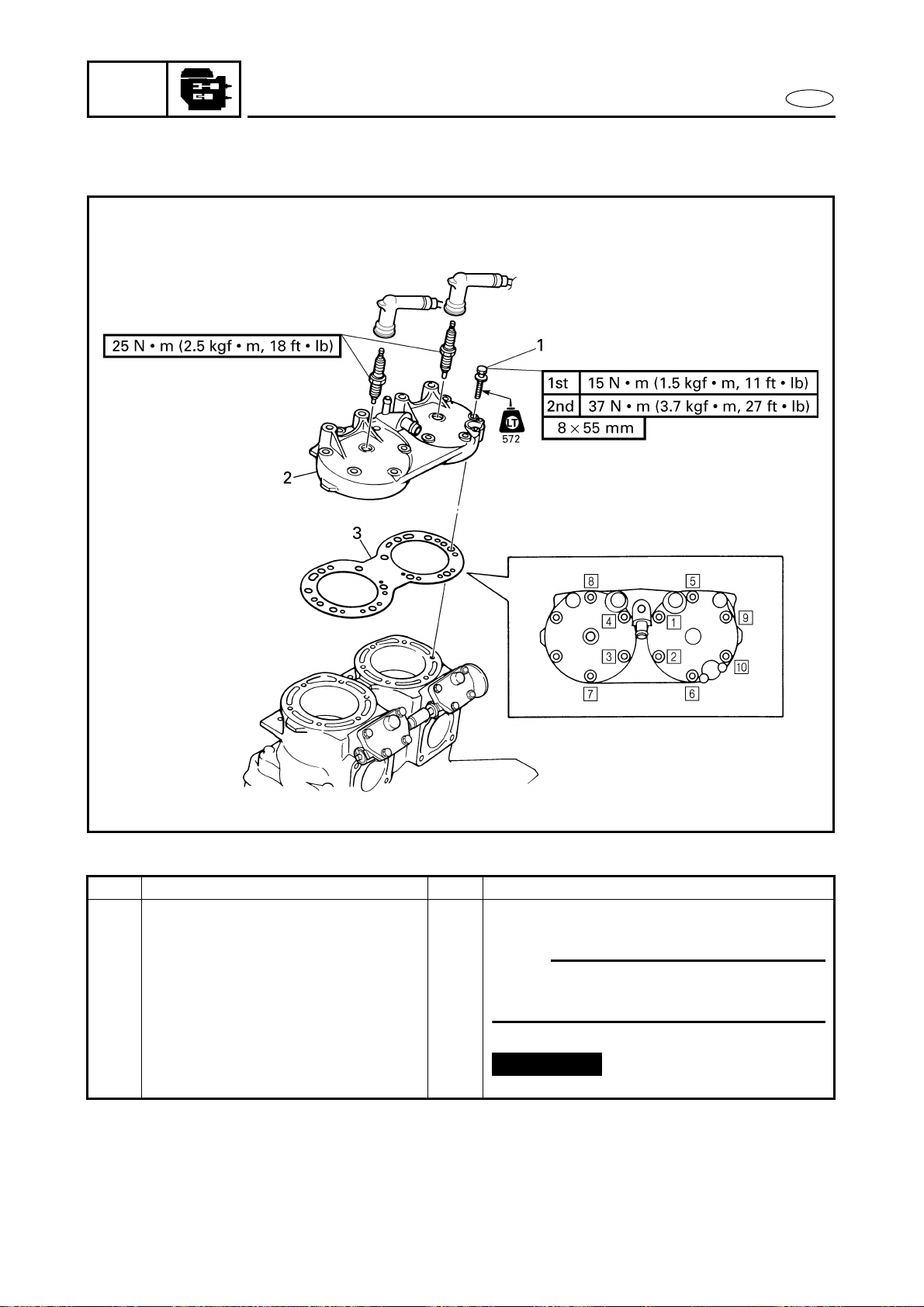
CYLINDER HEAD
CYLINDER HEAD
EXPLODED DIAGRAM
REMOVAL AND INSTALLATION CHART
Step Procedure/Part name Q’ty Service points
CYLINDER HEAD REMOVAL Follow the left “Step” for removal.
Exhaust manifold Refer to “EXHAUST MANIFOLD”.
1 Bolt 10
NOTE:
Tighten the bolts in the proper sequence
as shown and in two stages.
2 Cylinder head 1
3 Gasket 1
Reverse the removal steps for installation.
Not reusable
Loading ...
Loading ...
Loading ...