Loading ...
Loading ...
Loading ...
7-11
E
–+
ELEC
IGNITION SYSTEM
IGNITION SYSTEM PEAK VOLTAGE
WARNING
When checking the electrical components,
do not touch any of the connections of the
digital tester lead wires.
NOTE:
● If there is no spark or the spark is weak,
continue with the ignition system test.
● If a good spark is obtained, the problem is
not with the ignition system, but possibly
with the spark plug(s) or another compo-
nent.
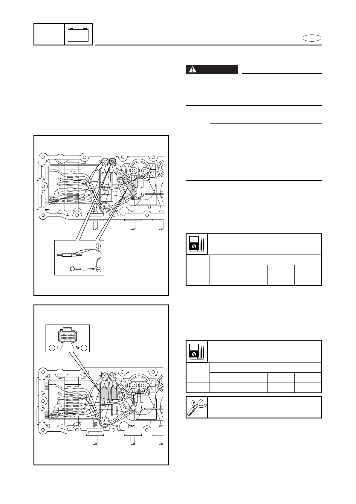
1. Measure:
● CDI unit output peak voltage
Below specification → Measure the
charge coil output peak voltage or
replace the CDI unit.
CDI unit output peak voltage:
Orange (O) – Black (B)
r/min
Unloaded Loaded
Cranking 2,000 3,500
V 85 110 205 200
2. Measure:
● Charge coil output peak voltage
Below specification → Replace the
charge coil.
Charge coil output peak voltage:
Brown (Br) – Blue (L)
r/min
Unloaded Loaded
Cranking 2,000 3,500
V 90 120 220 210
Test harness (8-pin):
YW-06779/90890-06779
Loading ...
Loading ...
Loading ...